HAL Id: hal-02021350
https://hal.archives-ouvertes.fr/hal-02021350
Submitted on 15 Feb 2019
HAL is a multi-disciplinary open access
archive for the deposit and dissemination of
sci-entific research documents, whether they are
pub-lished or not. The documents may come from
teaching and research institutions in France or
abroad, or from public or private research centers.
L’archive ouverte pluridisciplinaire HAL, est
destinée au dépôt et à la diffusion de documents
scientifiques de niveau recherche, publiés ou non,
émanant des établissements d’enseignement et de
recherche français ou étrangers, des laboratoires
publics ou privés.
Modeling System of Systems configurations
Franck Petitdemange, Isabelle Borne, Jérémy Buisson
To cite this version:
Franck Petitdemange, Isabelle Borne, Jérémy Buisson. Modeling System of Systems configurations.
2018 13th Annual Conference on System of Systems Engineering (SoSE), Jun 2018, Paris, France.
pp.392-399. �hal-02021350�
Modeling System of Systems configurations
Franck Petitdemange
IRISA
University of South Brittany [email protected]
Isabelle Borne
IRISA
University of South Brittany [email protected]
J´er´emy Buisson
IRISA
St-Cyr Coetquidan Military Schools [email protected]
Abstract—System of Systems (SoS) engineering is a challenging research direction because an SoS has distinctive characteristics in comparison to distributed systems. UPMD and SysML provide adequate frameworks and notations which help in the process of modeling and architecting SoS. Projects such as DANSE and COMPASS have selected the most relevant views among the numerous views of UPDM. By nature, an SoS evolves after its initial deployment. To deal with evolutions, the architect needs to model configurations, what was not considered in previous state of the art. Modeling configuration is indeed key before we can model the evolution itself. In this paper, our contribution is a new modeling process, based on UPDM and SysML, that helps the architect in designing the configuration of an SoS. The proposed process is illustrated with the case study of the French emergency service.
I. INTRODUCTION
The growing complexity of distributed systems leads to con-sider new engineering approaches. Among them, the system of systems (SoS) approach [1] addresses the case in which the constituents retain their own operational and managerial independence. The architecture of a system of systems focuses on the communications between its constituents, from which the overall behavior emerges. Model-based techniques are suitable to assist the architect with development, maintenance and adaptation steps. Models of constituents, connectors and environment are helpful to analyze trade-offs, to determine the contracts binding the SoS to the constituents, and to deal with complexity by documenting the structural, behavioral and communication aspects of the system of systems.
In comparison to classic distributed systems, an SoS rises specific issues that have to be dealt with, including hetero-geneity that follows from managerial independence of the constituents, difficulty to bound a system that is intrinsically open, and dynamicity. Previous state of the art has highlighted that UPDM provides an adequate framework and that SysML is a set of suitable notations when an architect wants to model an SoS, as evidenced by projects DANSE [2] and COMPASS [3]. While UPDM is a large framework with numerous views that address many aspects in the lifecycle of a project, only valuable views are selected in the UPDM framework in order to focus the work of the architect on specific concerns.
In this paper, we focus more specifically on the following characteristic: an SoS usually involves critical systems or economic systems (e.g. emergency services, transportation services) that cannot support the disruption or degradation of
some services. The SoS architecture continuously evolves and the architect needs to evaluate the current architecture to re-deploy it.
Accurate and precise models are therefore important ar-tifacts in such evolutionary development of SoSs. For this reason, in this paper, we focus more specifically on the modeling of configurations.
Our main contribution is a process that helps an SoS architect produce models for the configurations of the SoS under consideration. To do this, our contribution relies on the analysis of UPDM, DANSE and COMPASS. Then we contribute an adapted selection the UPDM views that are targeted at defining configurations for an SoS. We propose the SysML notations that appear to be the most relevant ones for these views.
The paper is organized as follows. The next section de-scribes the real case study that we use to illustrate the modeling process. Then, we investigate in Section III the related works in order to identify the main modeling issues and existing approaches to get the architectural charateristics needed to model SoS architecture configurations. Section IV describes the modeling process applied to the case study. Section V discusses and motivates the choices we have made in the proposed modeling process. Finally we draw conclusions and perpsectives.
II. MOTIVATING USE CASE
We present in this section a typical use case that will exemplify system of systems modeling. Our emergency rescue SoS is based on the French emergency service whose mission is to protect property and people. It is the setting up of an exceptional rescue organization in the case of natural disasters. Here it is about a flood of a whole area. The SoS is formed by the interaction of several systems which cooperate to fulfill an objective that they cannot provide individually.
The Figure 1 shows the main participants. There are several rescue teams which are the constituent systems collaboraring in the SoS. We consider:
• The departmental operation center of fire and help (CODIS1) which oversees and coordinates the whole
operational activity of a departmental fire and rescue service (SDIS2). Here two operation centers are involved
1Centre Op´erationel D´epartemental d’Incendie et de Secours 2Service D´epartemental d’Incendie et de Secours
Ambulance ERS CDG CODIS56 CODIS35 Civil security SAMU Hospital VTU UAV
Fig. 1. French Emergency Service
CODIS56 and CODIS35. A SDIS is responsible for transporting injured people, fighting fires and protecting property.
• The SAMU3is the center for emergency medical regula-tion and regulates urgent care resources (ambulances for example).
• Finally, the Civil Security, involved in major crisis situa-tions, can provide air assets.
Each type of system is deployed on each French department with its own funding and hierarchical structure, and it provides its own communication infrastructure. The constituent systems share the same telecommunication standard. Consequently, systems can communicate with each other and/or share their infrastructure.
We focus on three possible SoS configurations. The first one considers two SDIS having an operational collaboration, that is, they communicate directly, only with respect to field actions performed in order to fulfill the mission. Such a collaboration is set up, for instance, when one SDIS faces understaffing, and it therefore requests missing resources from a neighbour SDIS for a small-sized mission. In our scenario, this configuration is used when inhabitants call for emergency services in response to what is thought to be a localized flood.
In the second configuration, two SDIS have a tactical and a strategic collaboration, that is, a hierarchical command chain is set up. In addition to the operational collaboration, the tactical collaboration allows commanders to communicate with their subordinates, in order to give them instructions and collect reports with regard to field actions. The strategic collaboration ensures that consistent directions are adopted by the collaborating SDIS in order to address higher-level objectives defined by the mission. This second configuration is used when the crisis is bigger, hence calling for more resources than provided in the first configuration, and when these resources require tight coordination. In our scenario, the SoS evolves to this second configuration when the emergency services discover that the flood is more critical than they initially thought.
3Service d’Aide M´edicale Urgente
Finally, in the third configuration, a SDIS collaborates with the Emergency Medical Assistance Service (SAMU) and the civil security. This configuration occurs when the fire and rescue services need help from other services in order to deal with the crisis. In our scenario, SAMU is involved in order to regulate evacuation of wounded persons to closest hospitals, and civil security provides helicopter resources when the flood makes roads unusable.
III. SOS MODELINGISSUES
This section describes current practices in the context of SoS modeling. We also emphasize issues that are specific to the context of SoS.
On the one hand, standard modeling languages like UML and SysML provide acknowledged notations, and XMI allows tool interoperability. SysML relies on the core concept of block, which is the unit of which a system is composed. The block concept extends UML’s class with the notion of composite structure. Within a system, blocks interact through portsthat can be connected to one another. Like UML, SysML defines several diagrams, for both behavioral and structural aspects of the system. While not being exhaustive, use case diagrams describe interactions between users and the system; sequence, activity and state machine diagrams describe the course of action within blocks; block definition (bdd), internal block (ibd) and parametric diagrams describe blocks and their interactions.
On the other hand, the Unified Profile for DoDAF and MODAF (UPDM [4]) is an architectural framework that pre-scribes a comprehensive set of more than 40 views, which help in the process of modeling and architecting SoS. Like its name tells, it unifies the preexistent DoDAF and MODAF architec-ture frameworks, from the USA Department of Defense and UK Ministry of Defence respectively. The framework defines a collection of modeling intentions, by describing the objective of each specific view. The main groups of UPDM views are:
• Acquisition/Project Views (AcV/PV) describe organiza-tional aspects of projects, including their timeline and milestones.
• The All-Views (AV) gather global information and meta-data about elements of the architecture.
• Operational Views (OV) are a collection of views that
describe the activities involved in the SoS, as well as the resources (human or machinery) that perform these activities.
• Service-Orientated Views (SOV) describe the services, in terms of their interfaces, as well as the function services are expected to perform in order implement activities described in Operational Views.
• Strategic/Capability Views (StV/CV) are a group of cross-project long-term views that describe and organize capa-bilities of an organization, in anticipation of projects.
• System/Services Views (SV/SvcV) are a collection of views that describe how operational capabilities described in Operational Views and user requirements can be
real-ized in terms of equipment (or human) capability, that is, the specification of constituents involved in the system.
• Technical/Standards Views (TV/StdV) describe technolo-gies, rules and standards underpinning the implementa-tion of the system, hence providing a tool to anticipate technological progress or disruption that may affect the system.
While UML and SysML are only languages and do not provide any associated process, UPDM does not prescribe any modeling language for none of the views. The two technologies complement each other.
Instead of considering UPDM as a whole, and in order to avoid the numerous views of UPDM, previous work in the DANSE project [2] suggest to focus on selected views. Operational View OV-1 is intended to describe the mission or scenario of the SoS. Then, Operational View OV-5 aims at describing the tasks involved in achieving the mission. Next, Operational View OV-2 describes interactions and exchange of information between operational capabilities of the system. System View SV-5 traces what functions can implement the operational capabilities of OV-5. System View SV-1 addresses the composition and interaction of resources. Last, System View SV-10A is used in order to express functional and non-functional constraints.
The COMPASS project [3] also selects a subset of views, but, unlike DANSE, the COMPASS project does not follow UPDM. Though, some similarities can be observed, beginning with the distinction between Operational View and System View, named logical and physical, respectively. Most of the views match the DANSE project, since both projects follow the RUP process. But we observe the following differences. Instead of a single view OV-1 to describe the mission of the SoS, the COMPASS project uses two views: the first one gives an outline of the general organization; the other one focuses on the use cases expected from the SoS. Similarly, SV-1 is split into one view specifically targeted at the relationship between contituents and missions, and a separate view that describes collaborations within the SoS. Last, COMPASS has no counterpart for SV-10A.
Both DANSE and COMPASS reduce the architecture frame-work according to targeted objectives. The differences between the two reduced frameworks can be explained by different objectives: on the one side, DANSE is more targeted at SoS validation and adaptation to the environment; on the other side, COMPASS focuses on SoS evolution.
In the remainder of this section, we focus on specific modeling issues, and how these issues are addressed in the state of the art.
A. Heterogeneity
Since an SoS establishes a collaboration between constituent systems coming from several independent organizations, sev-eral stakeholders are involved in the production of the corre-sponding models. For instance, each fire department has it own system organization which is different of SAMU organization. But when it comes to the SoS, the models produced by
all these stakeholders must be combined. Heterogeneity of languages and practices is an obstacle.
Altogether, UML/SysML/XMI and UPDM provide frame-works that have good chance to be adopted by independent organizations. In practice, both DANSE and COMPASS use this combination for most of the diagrams they rely on.
In addition to modeling language and framework, the par-ticipation of several independent stakeholders rises the issue of concept (mis)alignment. To address this issue, [5], [6], [7], [8] propose to use traceability information in order to describe the relationship between related or similar concepts in models produced by different stakeholders. UPDM defines traceability views in order to help verifying that all the abstraction layers, e.g., Operational View and System View are consistent with one another.
B. SoS boundary
When an SoS is under definition, its border is generally blurred in the sense that identifying the constituents of the SoS is not trivial.
T-AREA [9] illustrates this issue with the example of Apple’s supply chain. At that time, all of the Apple’s direct suppliers for a specific category of batteries used to share the same second-level supplier, for one of the critical materials. Despite apparent redundancy when only the constituents di-rectly contributing to the mission of the SoS were considered, that shared supplier was in practice a single point of failure. This was revealed by an earthquake which caused a disruption of the shared supplier, according to [9]. In this case, if the second-level supplier is not part of model, reliability analysis of the SoS fails to report the weakness.
At the same time, in our case study of Section II, it is obvious that modeling all the emergency services from all the French departments (one hundred departments) is irrelevant. Even if they all possibly provide resources, only few of them have effective impact on the SoS. Only the services in the departments where the flood is located, plus possibly the neighbour departments, are significant.
The challenge is to decide which constituents should be included in the models, while omitting those constituents that do not provide valuable information.
In the DANSE project, described above, the boundary of the SoS is defined by the production of UPDM’s OV-1 expressed as a schematic picture. COMPASS uses in addition a use case diagram.
C. Dynamicity
Due to its nature, an SoS can include hundreds of con-stituents which are versatile. Consequently, dynamic models are not as usable as in simpler systems.
To face this issue, [10] suggests to restrict the use of state machine diagrams to the specification of contracts. [11], [12] propose to focus models on static regularity of the considered SoS. Instead of giving all the details of instances, the SoS is described by a set of constraints over how constituents can be connected to one another. The same approach is used in the
1: bound the SoS use case diagram
2: identify tasks activity diagrams 3: get constituents block definition diagrams 4: design interactions internal block diagram UPDM’s OV-1 UPDM’s OV-5
UPDM’s SV-1
Fig. 2. Modeling process
DANSE project in SV-1: an internal block diagram is used to model constraints on constituent connections. In that way, the model represents any configuration that conforms to the constraints, according to the environment.
D. Dynamic architecture
In our case study, we observe that an architecture is first defined as a response to the initial call to the emergency services. Then, while the SoS provides initial services, the environment evolves or the environment is discovered to be different from the initial thought. The SoS needs to evolve accordingly. New constraints are required during the SoS execution because new types of constituents are involved. Consequently, architecture models are required during SoS operation too. According to, e.g., [13], it is a good practice to ensure clean separation of concerns between reconfiguration logic and the rest of the architecture, while at the same time reusing the same paradigms and description languages. To the best of our knowledge, none of the previous SoS modeling approaches take this issue into account.
E. Positioning of our work
In our work detailed in Section IV, in comparison to related work, we specifically consider the configuration of the SoS and its modeling, thus leading to a different combination of choices. Indeed one objective of our work is in the context of dynamic reconfiguration. We also put the emphasis on the process in addition to the views and modeling language. UPDM serves as a basis for our work, because it appears to be well-adapted to the modeling of complex systems. With respect to the identification of the boundary of the SoS, we restrict to (semi-formal) structured notations: use case diagrams in the context of OV-1. With regard to dynamicity, we improve over previous approaches by introducing the use of architectural styles, and more specifically the architectural primitives [14].
IV. SYSTEM OF SYSTEMS MODELING PROCESS
This section is dedicated to the modeling process from which the objective is to obtain the various configuration
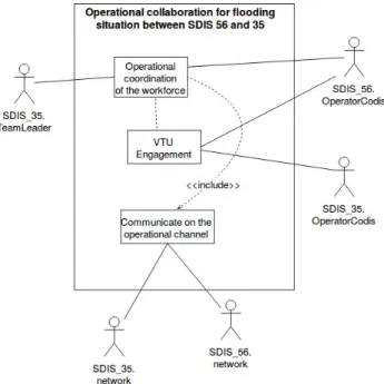
Fig. 3. Use case diag. of operational collaboration between SDIS 56 and 35
models of our SoS. As we explained in the previous section, we choose UPDM which is a good candidate to address the modeling of complex systems. Our modeling process is composed of four steps, which are outlined in Figure 2. The process we propose is a top-down process, where the architect first bounds the system under consideration by means of func-tional analysis. Then the architect produces activity diagrams for each use case to detail how the tasks performed by each constituent can be combined to achieve SoS-level functions. Next the architect identifies and composes the constituents by means of block definition diagrams. Last the architect obtains the configuration as an internal block diagram that describes interactions between the constituents that have been engaged in the system of systems to implement the activies previously described.
As we do not have room to detail the three configurations outlined in Section II, we will proceed with the process on the first case, which is the initial configuration.
The first step of the process aims at drawing out the bound-aries of the SoS under consideration. Similarly to UPDM’s Operational View OV-1, our goal is to enumerate the func-tionalities and missions expected from the SoS as well as to elicit the actors that are related to these missions. A use case diagram allows to describe the general organization with coarse-level actors.
Figure 3 describes the operational collaboration between two CODIS operators. The SDIS 56 operator needs to engage a constituent belonging to SDIS 35: a vehicle equipped with a pump (VTU). It is the first use case. Once the VTU is deployed on the ground, an operational coordination must be established between the SDIS 56 operator and the SDIS 35 team leader. It is the second use case. These two actors communicate via
an operational canal as we see in the use case at the bottom of the figure. Communication networks are concerned because part of the path from the vehicle to the intervention is covered by SDIS 35 network only.
The second step should detail the activities associated with each use case. The operational view OV-5 in UPDM translates into activity diagrams. For every use case previously identified, an activity diagram describes the normal course of operations. Figure 4 shows an activity diagram for the operational co-ordination of the workforce. It illustrates the communication protocol between the CODIS operator of SDIS 56 and the SDIS 35 team leader, and the sending of the instructions by the operator. The communication channel (here voice radio) is shared. In consequence, the French procedure requires that the CODIS operator first waits for the end of ongoing calls. We see that phases of identification, confirmation of listening and reception are required
The third step concentrates on the composition of the constituents. The system view SV-1 in UPDM suggests using block definition diagrams (bdd) to model the constituent organization. Figure 5 shows this diagram for our exam-ple. The actors are part of the constituents used by the SoS. To differentiate between constituent classes, stereotypes are mentioned such as <<human>>, <<software>> or <<material>> with their intuitive interpretation. We can see that the SoS aggregates CODIS operators, operational communication channels and team leaders. Furthermore, at the level of the material constituents we see that the CODIS has a fixed communication post, every operational channel has a relay and every team leader is in charge of a VTU.
Step four focuses on the interaction of constituents in the SoS. The internal block diagram (ibd) in figure 6 shows the operational coordination between SDIS 56 and SDIS 35. In our case study, CODIS operators communicate with team leaders. As seen in the activity diagram Figure 4, the collaboration protocol between a CODIS operator and a team leader is a disciplined commander/subordinate relationship. In the internal block diagram (ibd), we decided to reflect this fact by introducing a tactical layer (containing CODIS operator) and a distinct operational layer (containing team leader). In order to document such design decisions, we propose to rely on architectural primitives [14]. In Figure 6, the <<Group>> stereotype annotates packages that denote layers in the architecture. Package inclusion is used to connect constituents with the package that models the layer to which constituents belong. The internal block diagram hence states that CODIS operator belongs to the CODIS56 layer (tactic layer) and team leader belongs to the routine intervention layer (operational layer). According to its definition in [14], <<Group>> prevents direct communication between con-stituents from distinct layers, which is indeed the constraint we want to express, such that CODIS operator and team leader are forced to use the operational channel in order to communicate. The <<ShieldPort>> stereotype, from [14] annotates the only port that is allowed for cross-layer communications. OCL constraints enforce this restriction: these constraints ensure
Fig. 5. bdd operational coordination between SDIS 56 and 35
Fig. 6. ibd of operational coordination between SDIS 56 and 35
that any binding either connects ports of constituents that belong to the same <<Group>> package, or connects a port to a <<ShieldPort>> port. The <<IShield>> stereotype is used to denote shield interfaces, involved in cross-layer interactions.
Finally we can consider the evolutions of the studied config-uration. One evolution corresponds to the transition between the first and the second configuration described in section II. The number of constituents deployed for local intervention (FloodingIntervention layer) has increased considerably, so CODIS can no longer fully manage the intervention. A group leader has to be deployed to supervise a local intervention. CODIS 35 decides to deploy a group leader to assume the role of CODIS operator in the previous configuration. Following the same modeling approach, Figure 7 shows the resulting configuration that corresponds to a strategic collaboration beween SDIS 56 and SDIS 35. The <<Group>> primitives are reused to model the partition of constituents and to define communication points. The <<Layer>> primitives are intro-duced to capture constraints, with an attribute levelNumber that states the position of the layer in the hierarchical command chain. An OCL constraint ensures that cross-layer interactions through <<ShieldPort>> ports do not skip intermediate
Fig. 7. ibd of strategic collaboration between SDIS 56 and 35
levels in the command hierarchy. For example constituents from FloodingIntervention layer cannot directly communicate with constituents of the CODIS56 layer. Other configurations exist for this case study which we cannot expose here.
Without going into all the details, we have described the main steps of our modeling process which allows us to obtain a modeling of an SOS configuration. All the diagrams obtained form the basis of the SoS architecture. Our ultimate goal is to be able to reconfigure the architecture of a SoS and facilitate the transition from one configuration to another.
V. DISCUSSION
The work described in this paper lies in the context of a larger work towards assisting the architect in the design of reconfigurations when the SoS evolves. Even if this paper does not address the specific issues of evolution and reconfiguration, we keep this intention in mind as one of the goals of the model that results from the process of Section IV. More specifically, reconfiguring the SoS after deployment, when the SoS evolves, requires to ensure runtime properties such as timeliness, safety, continuity of operation. To correctly assess whether these properties are met, modeled configurations must capture exact and precise dependencies required by each constituent to provide its services to the SoS.
In this regard, each view we select contributes in the fol-lowing way. By adopting a top-down modeling approach, our process forces the architect to address SoS boundary first. OV-1 and the use-case diagram forces the architect to model the goals of the SoS as well as the actors that interact to contribute to these goals. Indeed, we use actors to model constituents. OV-5 and the activity diagram help fully investigating the boundary of the SoS. It requires the architect to tell what constituents contribute to each goal of the SoS, and what
is the contribution of each constituent, modeled by lanes in the activity diagram. It is an opportunity for the architect to discover possibly missing constituents, and therefore to ensure the boundary is correctly defined. SV-1, block definition diagram and internal block diagram yield to the configuration the architect intends to model: bdd details the type of the constituents that fulfill the goals previously described in OV-1; bdi shows dependencies between involved constituents, whose knowledge will later be useful to ensure safety and continuity of operation during reconfiguration.
In Section IV, we do not specifically address dynamicity of the architecture. No UPDM view accounts for this specific issue. We leave this issue for future contributions.
In this paper, we focus on a modeling process yielding to a model of the SoS configuration, with subsequent reconfig-uration in mind. This is the reason why we select only few of the UPDM’s views. Of course, the proposed process of Section IV can be included in a larger process that takes into account additional concerns. In the following, we review why other views are not relevant in the context we consider.
All-views gather only administrative information and in-dexes. Acquisition views focus on organizational aspects such as the definition of milestones and project timeline. These views are clearly not releveant with respect to our context.
Strategic views define organization-level capabilities, in-dependently of any system. In our case study, these views describe capabilities listed in Section II as well as additional capabilities such as chemical protection capabilities that have been set up, e.g., in anticipation of plant incident. While the content of strategic views may be helpful to design configuration, the anticipation process that yields to strategic views is not in the scope of our work.
Likewise, technical views track standards, rules and conven-tions that the system implementation must satisfy. Technical views describe for instance the communication conventions that we have implemented in the activity diagrams of Figure 4 or the hierarchical organization modeled by the <<Layer>> stereotype in Figure 7. The process of producing technical views is beyond the scope of our work.
Service-orientated views are used to associate capabilities identified in the operational views with services, that is, units of work with well-defined required and provided interfaces, which are in turn performed by the configuration described in system views. In Section IV, we skip service-orientated views, because we are more interested in the configuration that describes interactions between constituents, rather than the services they implement.
Regarding operational views, we have selected only OV-1 and OV-5, that is, the goals of the SoS as well as the normal course of actions for each goal. Indeed, other operational views concern information model and organizational aspects. Hence other operational views are not of interest in our context. Re-garding system views, we have chosen to consider only SV-1, the specification of constituent interactions. While SV-2 would describe links between constituents, we observe that sufficient information in this regard has already been embedded in SV-1.
SV-8 models system evolution as a timeline, where each mile-stone is characterized by a group of member constituents. In our approach, we rather foresee that each milestone is going to be characterized by a complete SV-1 model, hence containing a group of member constituents along with connection paths in order to be able to describe richer evolutions. Other system views address behavior models, non-functional properties and information models, and are therefore not of interest in the context of our work.
VI. CONCLUSION
In this paper, we proposed a process that helps an architect in designing the configurations of an SoS. For that we selected adequate UPDM views that are relevant with respect to this modeling objective. First, the architect draws out the bound-aries of the SoS under consideration, yielding to OV-1 as a use case diagram. In the second step, the architect details the activities associated with each use case, resulting in activity diagrams representing OV-5. In the third step, the architect focuses on the organization of the constituents, yielding to block definition diagrams for SV-1. Last, in the fourth step, the architect designs configurations, which describe constituent interactions as internal block diagrams.
To illustrate the proposed process, we applied it to a real use case, the French emergency service. After having informally described the scenario, our process allowed us to design several configurations, one for each evolution of the SoS. For space reason, in this paper, only two of these configurations are depicted.
For our future work, we plan to rely on the modeled configurations following the proposed process in order to further study the reconfiguration of the SoS architecture. To this end, we will reuse our previous work [15], that defines reconfiguration patterns, in order to model how the SoS changes its configuration each time an evolution is required.
REFERENCES
[1] A. Gorod, Ed., Case studies in system of systems, enterprise systems, and complex systems engineering, ser. Complex and enterprise systems engineering. Boca Raton: CRC Press, Taylor & Franciss Group, 2015. [2] T. Lochow, I. Sanduka, R. Bullinga, A. Arnold, R. Kalawsy, G. Cristau, M. Jung, C. Etzien, and E. Honour, “Concept Alignment Description,” Tech. Rep., 2013.
[3] M. Forcolin, Pietro - Felice Petrucco, R. Previato, R. Lloyd, R. Payne, C. Ingram, and A. Zoe, “Accident Response Use Case Engineering Analysis Report Using Current Methods & Tools,” Tech. Rep., 2013. [4] Object Management Group (OMG), “Unified Profile for DoDAF and
MODAF (UPDM), Version 2.1,” OMG Document Number formal/2013-08-04 (http://www.omg.org/spec/UPDM/2.1), 2013.
[5] T. Nguyen, “Models composition in FORM-L: Study of complex socio-cyber-physical systems and large scale systems of systems.” IEEE, Jun. 2016, pp. 1–6. [Online]. Available: http://ieeexplore.ieee.org/lpdocs/epic03/wrapper.htm?arnumber=7542916 [6] C. Neureiter, M. Uslar, D. Engel, and G. Lastro, “A standards-based approach for domain specific modelling of smart grid system architectures.” IEEE, Jun. 2016, pp. 1–6. [Online]. Available: http://ieeexplore.ieee.org/lpdocs/epic03/wrapper.htm?arnumber=7542888 [7] D. Mazeika, A. Morkevicius, and A. Aleksandraviciene, “MBSE driven approach for defining problem domain.” IEEE, Jun. 2016, pp. 1–6. [Online]. Available: http://ieeexplore.ieee.org/lpdocs/epic03/wrapper.htm?arnumber=7542911
[8] A. Morkevicius, L. Bisikirskiene, and G. Bleakley, “Using a systems of systems modeling approach for developing Industrial Internet of Things applications.” IEEE, Jun. 2017, pp. 1–6. [Online]. Available: http://ieeexplore.ieee.org/document/7994942/
[9] “Trans-Atlantic Research and Education Agenda in Systems of Sys-tems,” Tech. Rep., 2013.
[10] J. Bryans, J. Fitzgerald, R. Payne, and K. Kristensen, “Maintaining Emergence in Systems of Systems Integration: a Contractual Approach using SysML,” 2014.
[11] F. Oquendo, “Architecturally describing the emergent be-havior of software-intensive system-of-systems with SosADL.” IEEE, Jun. 2017, pp. 1–6. [Online]. Available: http://ieeexplore.ieee.org/document/7994941/
[12] J. Woodcock, A. Cavalcanti, J. Fitzgerald, P. Larsen, A. Miyazawa, and S. Perry, “Features of CML: A formal modelling language for Systems of Systems.” IEEE, Jul. 2012, pp. 1–6. [Online]. Available: http://ieeexplore.ieee.org/document/6384144/
[13] R. Allen, R. Douence, and D. Garlan, “Specifying and Analyzing Dynamic Software Architectures,” 1998. [On-line]. Available: https://www.evernote.com/shard/s495/sh/ef156f1f-5c83-468b-adc1-bac8c9719cc4/d9b5705ff6f5317c03d326d97cafdc2b [14] U. Zdun and P. Avgeriou, “A catalog of architectural primitives for
modeling architectural patterns,” Information and Software Technology, vol. 50, no. 9, pp. 1003–1034, 2008.
[15] F. Petitdemange, I. Borne, and J. Buisson, “Assisting the evolutionary development of SoS with reconfiguration patterns.” ACM Press, 2016, pp. 1–7. [Online]. Available: http://dl.acm.org/citation.cfm?doid=2993412.3004845