HAL Id: hal-00282768
https://hal.archives-ouvertes.fr/hal-00282768
Submitted on 15 Sep 2008
HAL is a multi-disciplinary open access
archive for the deposit and dissemination of
sci-entific research documents, whether they are
pub-lished or not. The documents may come from
teaching and research institutions in France or
abroad, or from public or private research centers.
L’archive ouverte pluridisciplinaire HAL, est
destinée au dépôt et à la diffusion de documents
scientifiques de niveau recherche, publiés ou non,
émanant des établissements d’enseignement et de
recherche français ou étrangers, des laboratoires
publics ou privés.
Priority image and video encoding transmission based
on a discrete Radon transform
Benoît Parrein, Fadi Boulos, Patrick Le Callet, Jean-Pierre Guédon
To cite this version:
Benoît Parrein, Fadi Boulos, Patrick Le Callet, Jean-Pierre Guédon. Priority image and video encoding
transmission based on a discrete Radon transform. IEEE Packet Video 2007, Nov 2007, Lausanne,
Switzerland. 6 p. �hal-00282768�
Priority Image and Video Encoding Transmission
Based on a Discrete Radon Transform
Benoît Parrein, Fadi Boulos, Patrick Le Callet, Jeanpierre Guédon
Université de Nantes, Nantes Atlantique Universités
IRCCyN CNRS UMR 6597, Polytech’Nantes, rue Christian Pauc, BP50609, 44306 Nantes cedex 3, France
Abstract— This paper presents an instance of priority encoding transmission system based on an exact and discrete Radon transform called the Mojette transform. The system includes an optimization process constrained jointly by the hierarchy of the source and by the channel property. In the framework of JPEG2000 image wireless transmission, the hierarchy is characterized by a perceptual objective quality assessment which is well correlated with the hu-man judgement and the channel estimation is performed by an exponential loss profile. The solution is compared with the JPEG2000 Wireless (JPWL) system based on the Peak Signal-to-Noise Ratio (PSNR) criterion and the Reed-Solomon codes. We also propose an extension of this work to H.264/AVC videos.
I. INTRODUCTION
Part 11 of the JPEG2000 standard extends it beyond the scope of image compression toward a global wire-less transmission architecture. The JPEG2000 Wirewire-less (JPWL) transmission consists of the core coding system and an Unequal Error Protection (UEP) scheme driven by semantic information reflecting the error sensitivity of each part of the bitstream (Fig. 1). An emphasized protection of the image and tiles headers has been pro-posed [1] because errors occurring at these levels have a dramatic impact on the overall image quality. References [2], [3], [4] have shown the efficiency of UEP schemes over traditional Equal Error Protection (EEP) schemes for multimedia content. Typically, Reed-Solomon (RS) codes are used as Forward Error Correction (FEC) codes. In [5], the RS codes (160,64), (80,25) and (40,13) are used. They introduce redundancy ratios of 1.5, 2.2 and 2.08, respectively. This robust protection improves significantly the probability of successful decoding independently of the channel conditions because the integrity of the headers is preserved in case of binary losses.
However, the symbol protection proposed in the JPWL standard does not address today’s wireless channels prac-tical considerations. More precisely, it ignores the effi-ciency of FEC mechanisms operating at the Multiple Ac-cess Control (MAC) layer or the physical layer (PHY) for a transmission using the IEEE 802.xx protocol (WLAN or WiMax). Besides, techniques like Hybrid Automatic Repeat reQuest (HARQ), Priority Encoding Transmission (PET) [6] and Multiple Description (MD) coding [7] are not considered. On the other hand, Peak Signal-to-Noise Ratio (PSNR) is used to characterize the error sensitivity of each part of the bitstream while it is generally agreed that it does not correlate very well with the human quality
" " residuals JPWL transcoder error protection part 1 codestream error-prone wireless channel part 11 codestream part 11 codestream with possible errors error sensitivity error correction residual errors part 1 codestream JPWL transcoder
Fig. 1. The UEP scheme of JPEG2000 Wireless (JPWL) [1].
judgement.
In this paper, we suppose that the PHY and MAC layers deliver faithfully the transmitted symbols. The contribution of this work is to propose a packet level UEP for still image coding based on a discrete Radon transform and driven by semantic metadata. The semantic metadata are provided by means of an objective image quality metric. Performances are compared with schemes based on Maximum Distance Separable (MDS) codes to which RS codes belong. An extension of our approach to a video content while taking into account the scalable profile of the source is also proposed.
Section II of this paper introduces the Mojette trans-form which is an exact and discrete Radon transtrans-form. Then, in Section III, we propose a Mojette-based UEP scheme that includes an optimal redundancy allocation and a perceptual objective quality metric. Section IV presents and discusses the experimental results. We give a short presentation of H.264/AVC bitstreams in Section V and we propose an extension of our work to videos. Finally, we describe related work in Section VI and we conclude the paper with future work in Section VII.
II. THEMOJETTETRANSFORM
The Mojette transform is an exact and discrete Radon transform. It easily describes an image by means of a finite set of 1D projections. Each angle of projection θ is defined by a couple of coprime integers (p, q) with
q
p = tan θ. The direct Mojette transform of an image
f(k, l), denoted by Mf , represents a set of N projections Mp,qf such as
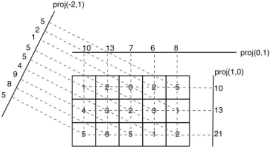
proj(1,0) 10 13 21 1 2 4 3 5 8 0 2 2 3 1 5 1 2 5 5 8 9 4 5 10 13 7 6 8 proj(0,1) proj(-2,1) 5 12 5
Fig. 2. Three Mojette projections of a 5×3 block. This set of projec-tions is sufficient to reconstruct the 2D block from its 1D projecprojec-tions.
Mf = {Mfpi,qi, i= 1, 2...N }. (1)
To compute each projection, we simply use additions in directions determined by the couple of integers(p, q). The resulting projections are composed of elements called bins. The value of a projection bin m is defined as the sum of pixels f(k, l) located on the discrete line determined by m= −qk + pl. The following equations stand for the definition of the Mojette-Dirac transform:
( [Mp,qf](m) = proj(p, q, m), [Mp,qf](m) =P k P l f(k, l)∆(m + kq − pl), (2) where∆ is the Kronecker function1
.
An example of Mojette projections is given in Fig. 2. Since each pixel contributes to one bin, the order of complexity is O(P Q = I) for any projection, where P is the width of the image, Q its height and I the number of pixels. If we want to compute an N projections set, the order of complexity isO(IN ), i.e. linear in the pixels number and in the projections number. The bins number of one(p, q) projection from a (P, Q) rectangular shape is given by the following formula :
#bins(P, Q, p, q) = |p|(Q − 1) + |q|(P − 1) + 1. (3) The Mojette transform can be expressed as the product of the transformation matrix M with the vector F of pixel values. Inverting the Mojette transform is equivalent to solving the linear system M.F = B where vector B is composed of the bin values. However, the binary matrix M is quite large (number of pixels × number of bins) and is rectangular and very sparse due to the frame nature of the Mojette. The Mojette reconstruction algorithm is based on the fact that all bins do not correspond to the same number of projected pixels. It is obvious that the value of a bin corresponding to a single pixel is identical to the pixel value. When such a one-to-one correspondence is found, the pixel value is copied from the bin value. The pixel is then removed from all the projections, i.e. its value is subtracted from all the
1∆(m) =
1 if m= 0 0 otherwise
bins where it projects. At this step, the remaining bins represent the Mojette transform of the unreconstructed part of the image. Reconstructing the image from a set of projections is then a process that iteratively:
1) finds a reconstructible bin, i.e. a bin projected from a single pixel,
2) “backprojects” its value onto the original pixel, 3) updates the projections,
until either the reconstruction is completed or no one-to-one correspondence between a bin and a pixel is found. A rectangular image P× Q can be reconstructed from a set of projections with directions{(pi, qi)} if and only if:
P i |pi| ≥ P or P i |qi| ≥ Q . (4)
Equation (4) (also known as Katz’ criterion [9]) must hold if and only if the reconstruction algorithm aforementioned is used. When building a set of reconstructible projections, we choose to comply with only one of the two conditions. For example, if we set all qi to 1, a P × Q image
will require exactly Q projections to be reconstructed whatever its width P is. From this reconstructible set of Q projections, we can build a redundant set by adding new projections. With N− Q extra projections, any subset of Q projections out of the total N is enough to reconstruct the image.
The simplicity of the Mojette transform has made it a useful tool in several applications: video indexing, source coding, multiresolution analysis and more recently secu-rity issues [8]. This discrete geometric tool represents the data through redundant and indistinguishable projections that are used to compensate packet losses or misordering.
III. THE PROPOSEDUEPSCHEME
We present in this section our proposed UEP scheme. This scheme is adapted to scalable sources and is based on the concept of “gray” packets, i.e. all data transport units that convey the source information have an equal weight at the decoding process. To achieve this, we use the Mojette transform which projects a 2D image into 1D projections resulting in transport units.
We describe the redundancy allocation scheme which combines the semantic importance of the information to protect and the channel condition. We then present the objective quality metric used in this work and we finally explain how the Mojette priority coding is performed. A. Optimal Redundancy Allocation Scheme
The Mojette transform can describe redundantly a source symbol by computing a number of projections greater than the number needed to reconstruct the original symbol. This protects the source symbol from the loss of some projections. An optimal redundancy allocation should vary the number of additional projections with two parameters: (i) the Error Sensitivity Descriptor (ESD) (ii) the probability of successful reception of the source
symbol. In the case of a scalable source, the redundancy is allocated with respect to the importance of each of the sub-streams. The optimization is performed by the mathematical function ρ that maps the sub-streams to the corresponding number of projections needed for recon-struction.
Let s be the sub-stream index ranging from 1 to L where L is the number of resolutions (or quality layers). The progressive reconstruction of the source assumes that sub-stream s can be used only if sub-stream s− 1 is reconstructed. Consequently, it is useless to protect the sub-stream s more than the sub-stream s− 1. The ρ function is thus monotonically increasing:
ρ0= 0 ≤ ρ1≤ ρ2...≤ ρL (5)
Let Qs be the quality measurement associated to the
image reconstructed from sub-streams 1 to s. With the scalability of the source, we suppose Qs ≥ Qs−1. We
then define a quality increment∆Qs, positive or null as:
∆Qs= Qs− Qs−1, (6)
with ∆Q0 = Q0. Let X be the random variable
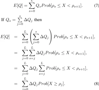
representing the number of received projections. The optimal ρ function maximizes the expected quality E[Q] at the decoding stage:
E[Q] = L X s=0 QsP rob[ρs≤ X < ρs+1]. (7) If Qs= s P j=0 ∆Qj then E[Q] = L X s=0 s X j=0 ∆Qj P rob[ρs≤ X < ρs+1], = L X j=0 L X s=j ∆QjP rob[ρs≤ X < ρs+1], = L X j=0 ∆Qj L X s=j P rob[ρs≤ X < ρs+1], = L X j=0 ∆QjP rob[X ≥ ρj]. (8)
Equation (8) takes into account the source properties (i.e. quality increment) and the feedback of the channel (i.e. reception probability). It represents the joint op-timization of source and channel coding. Any quality increment can be used, e.g. based on PSNR. A quality score given by a perceptual quality metric is proposed for our optimization process.
B. Objective Assessment of Quality Increments
The goal of an objective quality metric is to assess the quality of a signal (image or video) that has been processed (e.g. encoded). The evaluation is done by per-forming some computations on the processed signal and often on the original signal also. Generally, the processed
signal is a distorted version of the original signal and therefore we will use the expression “distorted signal” in this section to refer to the processed signal.
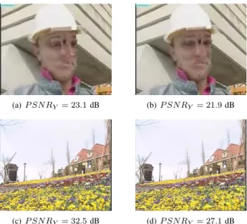
The assessment of the visual quality of images and videos is a complex task. The most widely used objective quality metric is the PSNR because of its low complex-ity. However, the performance of the PSNR metric is controversial (see examples in Fig. 3). The performance of an objective quality metric is measured by computing the correlation between the scores given by the objective metric and the Mean Opinion Score (MOS) given by a panel of human observers during subjective quality tests. The objective scores are compared to the MOS because the end-users of image and video are generally people. The subjective tests are conducted under ITU-R (Inter-national Telecommunication Union-Radiocommunication sector) recommendation BT.500-11 for still images and videos [10].
Fig. 3 shows two versions of a two different video frames with their corresponding PSNR values. We simu-late a real loss pattern over a Gilbert-Elliott channel [11]. For the top images, the left one has a higher Y-PSNR value than the right one. Nevertheless, it is clear that the left image has a worse visual quality than the right image. Also, the two bottom images exhibit the same visual quality while the left one has a higher Y-PSNR value than the right one. These examples show that PSNR is not the best objective quality metric for the assessment of image quality.
To overcome the limitations of PSNR, there has been an extensive research work during the past decade to develop image and video quality metrics that model the human judgement and the Human Visual System (HVS) response to various stimuli, both known to be highly non-linear. Ideally, the quality score given by a perceptual quality metric should be similar to the one given by a human subject. The work in [12] confirmed the efficiency of this approach by showing that objective quality metrics which integrate a model of the HVS yield good performance.
In this paper, we use the perceptual objective quality metric C4 [13] to evaluate the quality increment of each sub-stream of the image data. The good performance of the C4 metric tested on an image database of 100 JPEG2000 coded images motivated our choice. The qual-ity metric extracts the same features from the original and distorted signals, compares them and then combines a subset of them to obtain an objective score. The scores range from 1 (bad quality) to 5 (excellent quality). The (simplified) block diagram of the C4 metric used in this work is given in Fig. 4.
The originality of the metric is its perceptual aspect, i.e. it models some aspects of the HVS, namely, the Contrast Sensitivity Function (CSF) and the masking effect. The CSF simulates the HVS response to a stimulus as a function of its spatial frequency. The masking effect occurs when a degradation is amplified or masked by another signal (e.g. texture). By considering these two aspects, our quality metric tends to have a judgement
(a) P SN RY = 23.1 dB (b) P SN RY = 21.9 dB
(c) P SN RY = 32.5 dB (d) P SN RY = 27.1 dB
Fig. 3. (a) and (b) Frame 74 of the QCIF “Foreman” sequence. (c) and (d) Frame 96 of the CIF “Flower” sequence. Images are scaled down for display purposes.
Quality Score Original Image Distorted Image (CSF, Masking effect) Perceptual Model Features Extraction Perceptual Model Features Extraction Comparison
Fig. 4. The (simplified) block diagram of the C4 metric.
close to that of a human observer.
The features are extracted at precise positions in the picture called “characteristic points”. These points belong to the different Regions of Interest (ROI) of the picture. We choose the C4-combination 12 (see [13]) as the objective quality metric to evaluate the quality increments of the image data packets.
C. Mojette Priority Coding
The reconstruction of the source data is possible if and only if the criterion in (4) is checked. The angles are chosen in such a way that the resulting projections are equivalent at the reconstruction side. In addition, we only consider the vertical direction condition of (4). Hence, the selected angles are of the form (pi,1) for
i = 1, 2...N . In this case, Ms projections out of N
projections are necessary and sufficient to reconstruct the stream s. Knowing Ms and the sub-streams sizes, the
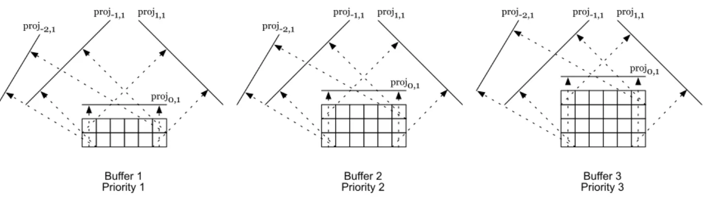
2D blocks can then be reconstructed for each stream s. These blocks can be seen as geometrical buffers whose capacities are function of the priority level of each sub-stream. That is, for greater buffers heights, less protection is provided. This is best illustrated in Fig. 5 which shows three geometrical buffers dedicated to three different packets priorities. The following set of four projections is transmitted:{proj−2,1, proj−1,1, proj0,1, proj1,1} out
of which a variable number of projections is necessary to reconstruct the different parts of the source data. Namely, two, three and four projections (out of four) are necessary to reconstruct buffer 1, buffer 2 and buffer 3, respectively.
IV. PERFORMANCE
We implement the approach described above to eval-uate its efficiency. We simulate a wireless environment wherein we transmit a JPEG2000 encoded image to which we apply our proposed UEP scheme.
A. Experimental Results
We run the test on a512 × 512 gray-scale Lena image. We simulate a wireless channel with an exponential packet loss model. The image is encoded by a lossless JPEG2000 coding scheme with a target rate of 0.5 bpp, 5 levels of decomposition and 2 quality layers. Thus, we obtain 12 packets where each packets represents a single quality layer of a decomposition level (including sub-band LL). The objective quality metric gives a score to each packet with regards to its decoding and the decoding of its predecessors. The empty packets resulting from the arithmetic coding and the packets with no significant amount of quality increment are aggregated with others in order to have scalable sub-streams with respect to their quality scores.
Therefore, we obtain 6 sub-streams composed of the following packets: aggregation of packets 1, 2 and 3; packet 4; packet 5; aggregation of packets 6, 7 and 8; aggregation of packets 9 and 10 and finally aggregation of packets 11 and 12. The resulting packets with their scores are summarized in Table I.
This optimal redundancy allocation scheme is now applied to a scalable source. The parameters used are the quality increment of each packet (calculated by the objective quality metric) and the successful reception probability (derived from our exponential loss model). The Mojette-based UEP of the bitstream (headers and image data) is characterized by a sufficient number of projections out of N transmitted projections. Let N = 16 which is the order of the number of JPEG2000 packets.
Fig. 6 shows the plot of optimal rate/expected qual-ity couples for MDS codes and two types of Mojette priority encoding transmission. We plot the expected quality scores as a function of the protection rates for an average packet loss rate of10%. An (almost) exhaustive search of all possible protection patterns, while taking into account the monotony of ρ function, led to this result. This search is not constrained by the bitrate nor by the
proj-1,1 proj0,1 proj1,1 Buffer 3 Priority 3 proj0,1 proj1,1 Buffer 2 Priority 2 proj-2,1 proj-1,1 proj0,1 proj1,1 Buffer 1 Priority 1 proj-2,1 proj-2,1 proj-1,1
Fig. 5. An example of a UEP scheme where buffer i is dedicated to priority i packets (for i= 1, 2, 3). Two, three and four projections (out of four) are necessary to reconstruct buffer 1, buffer 2 and buffer 3, respectively.
TABLE I
JPEG2000 PACKET AGGREGATION AND THE RESULTING SUB-STREAMS
#packet 1 2 3 4 5 6 7 8 9 10 11 12 size (bytes) 247 542 1266 2303 2615 991 1 113 472 1276 2741 3538 score 1.00 1.00 1.10 3.41 4.21 4.50 4.50 4.50 4.63 4.68 4.88 4.89 #sub-stream 1 2 3 4 5 6 source rate (bpp) 0.0807 0.1509 0.2307 0.2645 0.3178 0.5094 0 0.2 0.4 0.6 0.8 1 1.2 1.4 1.6 0.5 1 1.5 2 2.5 3 3.5 4 4.5 5
total rate including protection (in bpp)
Exp e ct e d q u a lit y a t th e re ce p ti o n (q u a lit y sco re s) MDS coding Mojette coding Mojettte coding (opt1)
Fig. 6. Optimal quality/rate analysis for MDS and Mojette priority encoding transmission. Quality scores are between 1 and 5. Rates includes the protection (joint source-channel coding rates). Two types of Mojette coding are presented depending on the non aggregation or the aggregation (opt1) of sub-streams with same protection levels into a same geometrical buffer.
expected quality in order to obtain the entire behavior of protection. The curves show 6 singularities. These significant increments of quality are due to the decision of the UEP system to transmit a new sub-stream in order to attain the desired quality.
By choosing the desired quality of the received image, we can infer the corresponding total bitrate and UEP. For instance, a quality score of 4.51 can be obtained by using a global bitrate of 0.41 bpp (joint source-channel coding). The protection pattern that maximizes E[Q] in (8) is found to be 11-11-12-12-13-17 for the 6 sub-streams. In this example, 11 represents the number of sufficient transport units needed to reconstruct sub-stream 1. Note that sub-stream 6 is not transmitted here for the desired quality. The transport unit size is 843 bytes.
Similarly, by choosing a bitrate threshold, we can predict the quality of a bitstream. For instance, if a redundancy ratio of5% is accepted for the protection of the JPEG2000 source, i.e. a global target rate of 0.525 bpp is tolerated, we can expect a maximal quality of 4.62 if we apply a protection pattern of 8-8-10-10-10-17 to the 6 substreams. In this case, sub-streams 1 and 2 can recover from the loss of up to half of the transport units.
The first Mojette encoding scheme associates each stream to a geometrical buffer, thus providing a fine data partitioning. The second proposed scheme (called opt1 in the figure) aggregates sub-streams which have same protection level into a same geometrical buffer. The concatenation of geometrical buffers improves sig-nificantly the rate/quality performance. The average rate reduction is approximately 4% when the aggregation (opt1) is performed. This gives an indication of the cost of information splitting that will be particularly considered for the protection of a video source.
B. Discussion
Sub-streams are reconstructed in decreasing order of priority (highest first). In contrast to JPEG2000 coding without protection, the loss of the first projections does not have a dramatic effect on the decoding process. The distortions are progressive whatever the position of the loss in the bitstream is and projections have an equal weight in the reconstruction process. The reverse algorithm can start as soon as one projection is received. Mojette-based UEP is quite close to the optimal bound given by Maximum Distance Separable codes (MDS). An overhead of 8.18% is observed. But the complexity for Mojette is in O(IN ) both for encoding and decoding against O(Ilog2
I) in MDS decoding [14] where I is recalled to be the number of information elements. The linear increase of the size of projection given in (3) allows this interesting linear complexity. Further, the source image used here has a relatively small size. The bigger the information source, the larger the geometrical buffers. This leads to a significant reduction of the overhead. For example, a 512 × 512 medical image with lossless source coding was tested with an overhead around2.5% independently of the average packet loss rate because the
protection increase is compensated by the prudence of the optimization algorithm to send a supplementary sub-stream.
Mojette coding is a (1 + ǫ)M DS code where ǫ rep-resents the decoding overhead for a sufficient set of projections. The parameter ǫ is quantified as the ratio of the sufficient bins number to the information elements number:
ǫ=#suf f icient_bins_number
I − 1. (9)
The sufficient bins number is equal to the sum of all bins in a sufficient set of projections. For q = 1, the projection size of (3) becomes :
#bins(P, M, p, 1) = |p|(M − 1) + P. (10) Considering the M projections in the sufficient set, the overhead becomes :
ǫ= (M − 1) PM
i=1|pi|
I . (11)
It means that among the sufficient bins number, the redundant ones are constant for a given set of projections. The overhead is inversely proportional to the amount I of information elements number. Finally, each consecutive relative integers pi can be used for the choice of a
projection that allows for a fine granularity protection in contrast to classic codes approaches [15]. The behavior of our UEP scheme with large amount of data motivates its application on packet video transmission system.
V. VIDEO EXTENSION
We discuss in this section the extension of our UEP scheme to encoded videos. Specifically, we target the H.264/MPEG-4 AVC (Advanced Video Coding) standard ([16], [17]) developed by the Joint Video Team (JVT) of ISO/IEC and ITU-T (Telecommunication Standardiza-tion sector). This coding standard outperforms all ex-isting coding standards at the expense of an increased complexity. Moreover, it is flexible and is adapted for network applications, i.e. the coding scheme covers two layers, namely, Video Coding Layer (VCL) and Network Abstraction Layer (NAL).
The VCL is the core of the coding system wherein the coding features are exploited: intra-frame prediction, motion estimation and compensation, transform coding, quantization and entropy coding. The NAL customizes the VCL data to adapt it to a specific transport system or storage media. We overview in the following the H.264/AVC bitstream composition and then we propose an adaptation of the Mojette-based UEP to the generated bitstream.
A. H.264/AVC Bitstream
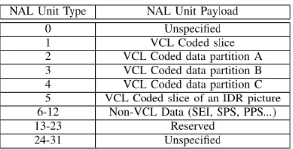
The basic unit of a H.264/AVC bitstream is the NAL unit. A NAL unit contains a 1-byte header followed by an integer number of data bytes representing a slice. Depending on the payload type, it can either be a VCL
TABLE II
NAL UNIT TYPES
NAL Unit Type NAL Unit Payload 0 Unspecified 1 VCL Coded slice 2 VCL Coded data partition A 3 VCL Coded data partition B 4 VCL Coded data partition C 5 VCL Coded slice of an IDR picture 6-12 Non-VCL Data (SEI, SPS, PPS...) 13-23 Reserved
24-31 Unspecified
NAL unit or a non-VCL NAL unit. VCL NAL units contain the coded video data and can be partitioned in order to allow the use of a UEP scheme. This H.264/AVC error resiliency feature is known as Data Partitioning (DP) and it is available in the Extended Profile only. It consists in partitioning a slice into three separate NAL units each of which containing a different part of the slice. Generally, partition A contains the most important data, namely, macroblocks headers, motion vectors and quantization parameters while partitions B and C include the transform coefficients of intra and inter-coded blocks, respectively. DP can thus be considered as a layering technique.
Non-VCL NAL units contain additional information useful for the decoding and the display of the video, e.g. Supplemental Enhancement Information (SEI), Sequence Parameter Set (SPS) and Picture Parameter Set (PPS). The different types of VCL NAL units are summarized in Table II (the definition of an IDR picture is given below). NAL units can be combined into three logical entities: coded picture, access unit and coded video sequence. A coded picture contains all the VCL NAL units repre-senting an original picture. It can be either a primary coded picture or a redundant coded picture. A primary coded picture is a coded representation of a picture which contains all macroblocks of the picture. A redundant coded picture is a coded representation of a picture or a part of a picture which may be used at decoding only if the associated primary coded (or decoded) picture is corrupted. It may not cover all the picture area when decoded.
An access unit comprises a primary coded picture, its associated redundant coded pictures and its associated non-VCL NAL units. The decoding of an access unit results in exactly one decoded picture.
A coded video sequence is a sequence of access units that consists, in decoding order, of an Instantaneous Decoding Refresh (IDR) access unit followed by zero or more non-IDR access units. An IDR picture is an intra-coded picture that allows after its decoding to all following coded pictures in decoding order to be decoded without inter prediction from any picture decoded prior to the IDR picture. The primary coded picture of an IDR access unit is an IDR picture.
B. Proposed Extension
We propose to implement our Mojette-based UEP scheme in the encoder. This approach allows us to control the size of the generated packets by limiting the par-titions size to the Maximum Transmission Unit (MTU) size. We suppose that non-VCL NAL units are received integrally (and in a errorless state) at the decoder side as we concentrate our study on the UEP of VCL NAL units. In the encoder, the VCL NAL units are processed depending on their type, i.e. NAL units of type 2 are put in the geometrical buffer B1 while NAL units of types
3 and 4 are put in the geometrical buffer B2, where
height(B1) < height(B2). Consequently, data buffers
B1 and B2 contain the base and the enhancement layer,
respectively. At this stage, a fixed number of projections is applied to the buffers’ data. This number can represent the number of available routes in case of multiple routing [18] or the number of servers in a grid of multiple storage servers [19]. Note that all projections are of the form (p, 1) where p ∈ Z. The bitstream is then unequally protected and the encoding process continues normally. At the decoder, the number of projections needed to retrieve the original data conveyed by type 2 NAL units is less than the one needed to retrieve the original data contained in types 3 and 4 NAL units. More precisely, a greater number of lost packets is tolerated in the case of type 2 NAL units.
This approach is supported by the fact that types 3 and 4 NAL units depend strongly on type 2 NAL units. That is, types 3 and 4 NAL units are not useful unless the header data contained in type 2 NAL units is available. Moreover, if types 3 and 4 NAL units are corrupted (or lost), the macroblocks headers and the motion vectors contained in type 2 NAL units can still be used to achieve a poor quality representation of the picture and thus preventing its loss [20].
The optimal redundancy allocation scheme described in section III is used here but with an adaptation to the H.264/AVC video bitstream. More precisely, besides the constraints of the channel condition (i.e. loss probability) and the source data importance (i.e. quality increment), we should consider two additional factors: (i) transmis-sion parameters such as MTU and efficient packet size (ii) temporal coherence of buffered data. Video data is voluminous, hence we should be able to limit the size of the buffered data to the MTU size or to set it to an optimal packet size over a given channel. Furthermore, the buffered data (in B1 and B2) should have the same
temporal length to ensure a correct assessment of the quality increments by the objective video quality metric. Mojette-based UEP is coupled with the perceptual redundancy allocation scheme based on an objective video quality metric: the Video Quality Metric (VQM) [21]. This perceptual quality metric outperforms all existing video quality metrics. It computes some characteristic in-dicators on specific spatio-temporal regions of the original and the processed videos. The optimal ρ∗ function is then computed for each of these regions.
VI. RELATEDWORK
Besides DP, H.264/AVC standard comprises several error resilience features such as Flexible Macroblock Or-dering (FMO) and Redundant Slice (RS). Despite the fact that encoding complexity increases when these features are used, it has been shown that they allow a graceful degradation of the video quality with an increasing error rate, e.g. over IP networks [22].
Reference [23] has demonstrated that the use of FMO associated with a UEP scheme, namely, RS codes outper-forms classical H.264/AVC transmission schemes in terms of decoded video quality. Furthermore, the utilization of DP in H.264/AVC mobile communication has yielded a lower percentage of entirely lost frames [20]. Also, when coupled with other techniques, the performance of H.264/AVC error resilience tools increases. For instance, joint DP and rate-distortion optimized mode selection (size of macroblock, prediction type) improves the de-coded video quality [24]. An extensive study of prioriti-zation and layering techniques for H.264/AVC videos in [25] shows that the combination of DP and Turbo Codes (TC) and flexible modulation techniques outperforms the combination of DP and TC only.
VII. CONCLUSION ANDFUTUREWORK
We presented in this work a UEP scheme based on a discrete and exact Radon transform: the Mojette trans-form. We showed that coupling this protection technique with a perceptual rate-distortion approach yields good results despite a supplementary overhead. We also demon-strated that this overhead is inversely proportional to the amount of source information. The main advantage of the Mojette-based UEP is its linear complexity in the number of elements and projections. We finally proposed an extension to our approach for H.264/AVC videos.
This work can be further extended in two main di-rections. First, we would like to implement and test our approach on H.264/AVC encoded sequences. Then we envision testing it on sequences encoded with the Scalable Video Coding (SVC) extension of H.264/AVC, as a scalable source is the ideal target onto which a UEP scheme applies.
REFERENCES
[1] “JPEG2000 image coding system-Part 11: Wireless", ISO/IEC JTC 1/SC 29/WG 1, March 2005.
[2] F. Zhai, Y. Eisenberg, T. N. Pappas, R. Berry and A. K. Katsagge-los, “Rate-Distortion Optimized Product Code Forward Error Cor-rection for Video Transmission over IP-based Wireless Networks”, in Proceedings of IEEE International Conference on Acoustics, Speech and Signal Processing, ICASSP, vol. 5, pp. 857-860, May 2004.
[3] C. Poulliat, I. Fijalkow and D. Declercq, “Scalable Image Trans-mission using UEP Optimized LDPC Codes”, Third International Symposium on Image/Video Communications over fixed and mobile networks, September 2006.
[4] R. Chakravorty, S. Banerjee and S. Ganguly, “MobiStream: Error-Resilient Video Streaming in Wireless WANs Using Virtual Chan-nels”, in Proceedings of IEEE International Conference on Com-puter Communications, pp. 1-14, April 2006.
[5] F. Dufaux and D. Nicholson, “JPWL: JPEG2000 for Wireless Applications”, in Proceedings of SPIE Applications of Digital Image Processing XXVII, vol. 5558, pp. 309-318, November 2004.
[6] A. Albanese, J. Blömer, J. Edmonds, M. Luby and M. Sudan, “Priority Encoding Transmission”, in IEEE Transactions on Infor-mation Theory, vol. 42, pp. 1737-1744, November 1996. [7] V. Goyal, “Multiple Description Coding: Compression Meets the
Network”, IEEE Signal Processing Magazine, vol. 18, pp. 74-93, September 2001.
[8] J. Guédon and N. Normand, “The Mojette Transform: the First Ten Years”, in Proceedings of 12th International Conference on Discrete Geometry for Computer Imagery, DGCI, vol. 3429, pp. 79-91, April 2005.
[9] M. Katz, “Questions of Uniqueness and Resolution in Reconstruc-tion from ProjecReconstruc-tions”, Lecture Notes in Biomathematics, Springer-Verlag New York, 1978.
[10] ITU-R Recommendation BT.500-11, “Methodology for the Sub-jective Assessment of the Quality of Television Pictures”, June 2002.
[11] Information Society Technologies, “Loss Patterns Acquired During the WCAM Annecy 2004 Measure-ment Campaigns”, WCAM project, retrieved from http://wcam.epfl.ch/losspatterns/losspatterns.html
[12] M. Carnec, P. Le Callet and D. Barba, “Full Reference and Reduced Reference Metrics for Image Quality Assessment”, In-ternational Symposium on Signal Processing and its Applications, ISSPA, July 2003.
[13] M. Carnec, P. Le Callet and D. Barba, “Visual Features for Image Quality Assessment with Reduced Reference”, in Proceedings of IEEE International Conference on Image Processing, ICIP, vol. 1, pp. 421-424, September 2005.
[14] J. Lacan, V. Roca, J. Peltotalo and S. Peltotalo, “Reed-Solomon Forward Error Correction (FEC)”, draft-ietf-rmt-bb-fec-rs-02.txt (work in progress), December 2006. Available at http://hal.inria.fr/docs/00/12/19/05/HTML/index.html
[15] A. Mohr, E. A. Riskin and R. E. Ladner, “Unequal Loss Protec-tion: Graceful Degradation of Image Quality over Packet Erasure Channels through Forward Error Correction”, IEEE Journal on Selected Areas in Communications, vol. 18, no. 6, pp. 819-828, June 2000.
[16] Joint Video Team of T and ISO/IEC JTC 1, “Draft ITU-T Recommendation and Final Draft International Standard of Joint Video Specification (ITU-T Rec. H.264 | ISO/IEC 14496-10 AVC),” Joint Video Team (JVT) of ISO/IEC MPEG and ITU-T VCEG, JVT-G050r1, May 2003.
[17] T. Wiegand, G. J. Sullivan, G. Bjontegaard and A. Luthra, “Overview of the H.264/AVC Video Coding Standard”, in IEEE Transactions on Circuits and Systems for Video Technology, vol. 13, no. 7, July 2003.
[18] R. Leung, J. Liu, E. Poon, A. Chan and B. Li, “MP-DSR: A QoS-Aware Multi-Path Dynamic Source Routing Protocol for Wireless Ad-Hoc Networks”, in Proceedings of 26th Annual IEEE Conference on Local Computer Networks, LCN, pp. 132-141, November 2001.
[19] J. Guédon, B. Parrein and N. Normand, “Internet Distributed Image Information System”, Integrated Computer-Aided Engineer-ing, vol. 8, n. 3, pp. 205-214, 2001.
[20] T. Stockhammer and M. Bystrom, “H.264/AVC Data Partitioning for Mobile Video Communication”, IEEE International Confer-ence on Image Processing, ICIP, October 2004.
[21] M. H. Pinson and S. Wolf, “A New Standardized Method for Objectively Measuring Video Quality”, in IEEE Transactions on Broadcasting,vol. 50, n. 3, pp. 312-322, September 2004. [22] S. Wenger, “H.264/AVC over IP”, in IEEE Transactions on
Cir-cuits and Systems for Video Technology, vol. 13, no. 7, July 2003. [23] N. Thomos, S. Argyropoulos, N. V. Boulgouris and M. G. Strintzis, “Robust Transmission of H.264/AVC Video Using Adaptive Slice Grouping and Unequal Error Protection”, IEEE International Con-ference on Multimedia & Expo, ICME, July 2006.
[24] Y. Zhang, W. Gao and D. Zhao, “Joint Data Partition and Rate-Distortion Optimized Mode Selection for H.264 Error-Resilient Coding”, IEEE International Workshop on Multimedia and Signal Processing, MMSP, October 2006.
[25] M. M. Ghandi, "Layered Video Coding for Wireless Communica-tions", PhD thesis, University of Essex, 2006.
![Fig. 1. The UEP scheme of JPEG2000 Wireless (JPWL) [1].](https://thumb-eu.123doks.com/thumbv2/123doknet/8250210.277662/2.892.499.791.329.479/fig-uep-scheme-jpeg-wireless-jpwl.webp)