THE JOINT EDUCATION MASTER PROGRAM
UNIVERSITY OF LIÈGE – BELGIUM WATER RESOURCES UNIVERSITY – VIETNAM
DESIGN
MONOPILE
FOUNDATION
OF
OFFSHORE
WIND
TURBINES
A master thesis submitted in partial
fulfillment of the requirements for the
Master of Science degree in
Sustainable Hydraulic Structures
by
Mai Anh Quang
Supervisor:
Professor Philippe Rigo
Assoc. Professor Trinh Minh Thu
Lời cảm ơn
Qua luận văn này, những dòng đầu tiên tác giả muốn được bày tỏ lòng biết ơn chân thành tới những người đã nhiệt tình giúp đỡ, chỉ bảo, tạo mọi điều kiện thuận lợi suốt từ những buổi đầu của khóa học cho đến những ngày hoàn thiện luận văn.
Đầu tiên tác giả muốn được bày tỏ lòng biết ơn sâu sắc tới thầy Philippe Rigo, giáo sư hướng dẫn chính, người đã định hướng nghiên cứu, tận tình đọc và sửa lỗi cả về mặt học thuật và câu chữ trong luận văn.
Lời cảm ơn chân thành xin được gửi tới ban ANAST – khoa ARGENCO – đại học Liège (Bỉ), nơi đã hỗ trợ kinh phí và hướng dẫn khoa học để luận văn này được thực hiện tại Ulg. Tác giả xin được bày tỏ lòng biết ơn đến giáo sư Federic Colin (địa kỹ thuật) và giáo sư Vincent Denoel (động lực học) đã tận tình giúp đỡ trong các vấn đề chuyên ngành liên quan trong thời gian thực hiện luận văn.
Tác giả mong muốn được nói lời cảm ơn tới các lãnh đạo Viện Thủy Lợi và Môi Trường – trường ĐHTL vì những sự giúp đỡ về vật chất và khoa học trong quá trình học tập tại thành phố HCM. Đặc biệt là hai người thầy đáng kính, phó giáo sư, tiến sĩ Trịnh Công Vấn và phó giáo sư, tiến sĩ Trịnh Minh Thụ, những người không chỉ động viên, giúp đỡ về khoa học mà còn là chỗ dựa tinh thần của tác giả trong suốt khóa học này.
Tác giả không quên công ơn của những người tâm huyết xúc tiến sự hình thành và phát triển của chương trình hợp tác đào tạo có chất lượng này. Một môi trường học tập thực sự hữu ích cho những kỹ sư đã có kinh nghiệm thực tế.
Lời cảm ơn của tác giả cũng xin được trân trọng gửi tới các thầy cô giáo đến từ WRU và Ulg đã nhiệt tình chỉ bảo và dành nhiều cảm tình cho tác giả trong suốt sáu mô đun của chương trình tại thành phố HCM.
Cuối cùng xin được dành những tình cảm chân thành gửi tới các anh chị em lớp Cao học Việt – Bỉ khóa 1, những người đã dành cho tác giả nhiều tình cảm ưu ái và sự động viên giúp đỡ trong quá trình học tập xa nhà.
2
Acknowlegments
I wish to thank, first and foremost, Professor Philippe Rigo – University of Liège (Belgium) – the promoter and supervisor of my master thesis, who read and corrected all technical as well as English mistakes in the thesis.
This thesis would have remained a dream had it not been for ANAST Department – ARGENCO Faculty – University of Liège (Ulg), who gave me financial support to do my research in Ulg.
It gives me great pleasure in acknowledge the support and help of Professor Frederic Collin and Professor Vincent Denoël – ARGENCO Faculty – on geotechnical and dynamic issues of the foundation pile under cyclic loading.
I owe my deepest gratitude to leaders of Institute for Water and Environment Research – Water Resources University – for all the academic helps and financial support that they gave me during the time I was taking this master course in Ho Chi Minh City.
I cannot find words to express my gratitude to Associate Professor Trinh Minh Thu and Associate Professor Trinh Cong Van for their scientific supports and wisely advices.
I would like to thank all Professors and Lecturers giving lectures in six modules of the “Sustainable Hydraulic Structures” master course for all their favors given to me.
This thesis would not have been possible unless Coordinators from both WRU and Ulg have made their greatest efforts to establish this Joint Master Course between the two Universities.
I share the credit of my work with all of my colleagues in the master class for their supporting and encouraging while l was living in Ho Chi Minh City.
I am indebted to my parents and my wife for all the loves they have given and all the difficulties they have borne during my study.
Tóm tắt nội dung luận văn
THIẾT KẾ NỀN CỌC ĐƠN CHO TUABIN GIÓ NGOÀI KHƠI
Sự tối ưu hóa thiết kế là vấn đề cấp thiết cho sự phát triển của ngành công nghiệp điện gió ngoài khơi. Vì tiến trình này mất rất nhiều thời gian nên các thông số được lựa chọn để tính toán tối ưu hóa càng giảm được nhiều càng tốt. Từ đó, một vấn đề nảy sinh là có thể loại bỏ được phần nền móng trong quá trình tối ưu hóa này hay không. Để thấy được tầm quan trọng của việc kể đến cọc nền trong ứng xử động lực học của toàn bộ công trình, trước tiên cần phải xác định các kích thước của nó dựa trên các yêu cầu về thiết kế theo trạng thái giới hạn cực hạn và trạng thái điều kiện làm việc sử dụng các tiêu chuẩn thiết kế hiện hành, sau đó so sánh ứng xử động lực học giữa mô hình ngàm tại đáy biển và mô hình có phần kết cấu nền. Việc mô hình hóa phần nền được tiến hành bằng phương pháp dầm trên nền đàn hồi phi tuyến có kể đến ứng xử của đất dính và đất rời đối với cọc nền. Với dự án tuabin gió ngoài khơi được chọn có công suất 7MW và chiều cao 115m đến đáy biển, việc tính toán cho thấy cần phải có cọc nền chiều dài 26m, đườn kính 6m và chiều dày 8cm. Ứng xử động lực học của hai mô hình cho thấy rằng sẽ là không an toàn nếu bỏ qua phần kết cấu nền trong quá trình tối ưu hóa thiết kế. Ngoài ra khả năng đóng góp sự giảm chấn của đất nền chiếm tỷ trọng lớn nhất trong ứng xử động lực học của toàn bộ kết cấu. Kết quả nghiên cứu sẽ có ích trong việc xem xét các thông số cần tối ưu hóa trong thiết kế tuabin gió ngoài khơi, cũng như việc chọn lựa phương pháp giải thích hợp cho các phương trình động lực học trong tiến trình tối ưu hóa.
Abstract
DESIGN MONOPILE FOUNDATIONS OF OFFSHORE WIND TURBINES
Design optimization is crucial to the development of the offshore wind turbine industry. This time consuming process is better to be done with a number of input parameters that is as short as possible. Whether the foundation pile part can be neglected in the design optimization process of an offshore wind turbine structure is a question need to be answer. In order to see the importance of the presence of the foundation pile in dynamic behavior of the whole structure, dimensions of the foundation pile must be determined basing on requirements in ultimate limit state and serviceability limit state in current design standards. Afterward, the differences in dynamic behavior between a fixed-at-seabed tower model and a tower with foundation model must be observed. Beam nonlinear Winkler Foundation model in addition to gapping and non-gapping behavior in pile-soil interface were used to model the foundation. With the chosen offshore wind turbine project of 7MW and 115m high to seabed, a foundation pile with a penetration length of 26m, diameter of 6m and wall thickness of 8cm had been found. The dynamic behavior of the two models showed that it was not on the safe side if the foundation was neglected in design optimization process. And that the internal damping of the soil was the most important factor in behavior of the structure. These results will be useful for reconsidering parameters in design optimization process of monopile offshore wind turbines as well as choosing suitable methods to solve dynamic equations in the optimization procedure.
4
Table of Contents
Chapter I. Introduction ... 12
1.1. Foundation of offshore wind turbines ... 12
1.2. Design Optimization Project for Offshore Wind Turbines... 16
1.3. Which type of foundation should be chosen? ... 17
1.4. Tasks of the thesis... 17
1.5. Method to carry out... 18
1.6. Structure of the thesis ... 18
Chapter II. Support structure of monopile OWTs - components, fabrication and installation ... 19
2.1. Introduction ... 19
2.2. How it works? ... 19
2.3. Components of the support structure ... 20
2.3.1. Definitions ... 20
2.3.2. Design elevations ... 20
2.3.3. Support structure components ... 20
2.4. Fabrication ... 21
2.5. Installation ... 22
Chapter III. Design Methodology ... 28
3.1. Introduction ... 28
3.2. Design objective ... 28
3.3. Design process for offshore wind turbine support structures ... 29
3.3.1. Design Sequence ... 29
3.3.2. Design Load Cases ... 30
3.3.3. Limit State Checks ... 30
3.3.4. Design evaluation ... 31
3.4. Design criteria ... 32
3.4.1. From requirements to criteria ... 32
3.4.2. Natural frequencies ... 32
3.4.3. Strength criteria ... 33
3.4.4. Design criteria for monopile foundations ... 34
3.4.5. Design requirements for manufacturing and installation ... 36
Chapter IV. Related Theories ... 38
4.1. Introduction ... 38
4.2. The basics of dynamics ... 38
4.3. Damping in offshore wind turbines structures ... 40
4.3.1. Definition of damping ... 40
4.3.2. Damping for piled offshore support structure ... 41
4.3.3. Damping of soil (piled structure) ... 42
4.4. Sources of excitations ... 43
4.5. Statistical methods and Deterministic approach ... 43
4.6. Wind ... 45
4.6.1. Mean annual wind speed and wind speed frequency distribution ... 45
4.6.2. Increase wind speed with altitude ... 46
4.6.4. Wind turbine classes ... 47
4.6.5. Wind Rose ... 48
4.6.6. Assessment of wind loads on the support structure ... 48
4.7. Wave ... 49
4.7.1. General characteristics of waves ... 50
4.7.2. Reference sea states... 50
4.7.3. Wave Modeling ... 51
4.8. Current ... 53
4.9. Combined Wind and Wave Loading ... 54
4.9.1. Horizontal to Moment Load Ratio ... 54
4.9.2. Combination Methods... 54
4.10. Effect of cyclic loading to foundation ... 54
4.10.1. Cyclic degradation effects ... 54
4.10.2. Loading rate effects ... 55
4.11. Basis of Soil Mechanics... 56
4.11.1. Stress-strain behavior, stiffness and strength ... 56
4.11.2. Elasticity ... 57
4.11.3. Perfect Plasticity ... 57
4.11.4. Combined Elasto-Plastic Behavior ... 58
4.12. Types of Soil Model ... 59
4.12.1. Plasticity Models ... 59
4.12.2. Finite Element Models ... 60
4.12.3. Other Technique ... 60
4.13. Winkler model ... 61
4.13.1. Beam Nonlinear Winkler Foundation ... 61
4.13.2. Pile-soil interface ... 62
4.13.3. Load-displacement relationship ... 62
4.14. Sap2000 and methods to solve a nonlinear dynamic analysis ... 64
4.14.1. Sap2000 software ... 64
4.14.2. Dynamic equilibrium ... 65
4.14.3. Step-by-step solution method ... 65
4.14.4. Mode superposition method ... 66
4.14.5. Solution in frequency domain ... 66
Chapter V. Preliminary Design for Support Structure of a Chosen OWT Project ... 67
5.1. Introduction ... 67
5.2. Structure definitions and limitations ... 67
5.2.1. The chosen turbine ... 67
5.2.2. Tower and substructure design ... 68
5.2.3. Corrosion ... 71
5.3. Environmental conditions ... 72
5.3.1. Site data ... 72
5.3.2. Sea conditions ... 72
6
5.3.5. Further meteorological – oceanographical parameters ... 72
5.3.6. Soil conditions ... 72
5.4. Load combination for ULS ... 73
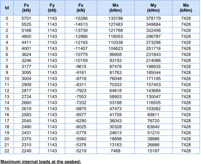
5.5. Results of internal forces for foundation design ... 74
5.5.1. For ULS design ... 74
5.5.2. For SLS check ... 74
5.6. Results of natural frequency analysis... 74
Chapter VI. Foundation pile design ... 76
6.1. Introduction ... 76
6.2. Ultimate limit state design ... 76
6.2.1. Axial capacity ... 76
6.2.2. Lateral capacity ... 85
6.2.3. Structural Capacity of the steel pile ... 93
6.3. Serviceability limit state check ... 101
6.3.1. General ... 101
6.3.2. Geometry model ... 101
6.3.3. Loads ... 103
6.3.4. Results of calculation ... 108
6.3.5. Conclusions of SLS calculation ... 113
6.4. Effect of foundation in dynamic behavior of the structure ... 114
6.4.1. Reconsidering the model ... 114
6.4.2. Spring foundation vs. fixed foundation ... 116
6.4.3. Linear spring vs. nonlinear spring foundation ... 119
6.5. Effect of p-y curve on the dynamic behavior of structure ... 120
Chapter VII. Conclusions and Future works ... 121
7.1. Conclusions ... 121 7.2. Future works ... 121 Bibliography ... 122 Honor Statement ... 124 Appendix 1. T-Z curves ... 125 Appendix 2. Q-Z curves ... 128
Appendix 3. P-Y curves ... 129
List of Figures
Figure I.1: Nysted Offshore Wind Farm ... 12
Figure I.2: Mechanical system of an offshore wind turbine ... 13
Figure I.3: a) Standard Monopile Structure, b) Supported Monopile Structure. ... 14
Figure I.4: a) Tripod Structure, b) Gravity Pile Structure. ... 14
Figure I.5: Lattice Tower. ... 15
Figure I.6: Gravity Base Structure. ... 15
Figure I.7: Suction Bucket Structure... 15
Figure I.8: Tension-Leg Platform. ... 16
Figure I.9: Low-roll Floater. ... 16
Figure I.10: First offshore wind facility Vindeby in Denmark ... 16
Figure I.11: The interface of the software EOL OS ... 17
Figure II.1: Overview of offshore wind turbine terminology ... 19
Figure II.2: Rolling and welding of a foundation pile ... 22
Figure II.3: Pile driving at Offshore Wind Farm Egmond aan Zee ... 23
Figure II.4: Drilling equipment at Blyth ... 24
Figure II.5: Schematic example of scour protection ... 24
Figure II.6: Transition piece installation ... 25
Figure II.7: Lifting of a tower section for installation ... 26
Figure II.8: Installation of a rotor in one piece ... 26
Figure II.9: Various stages in the installation of a turbine using the bunny-ear method ... 27
Figure III.1: Design process for an offshore wind turbine ... 29
Figure IV.1: Single degree of freedom mass-spring-damper system ... 38
Figure IV.2: a) Quasi-static b) resonant and c) inertia dominated response ... 39
Figure IV.3: Frequency response function ... 40
Figure IV.4: Measured time history of wind speed ... 47
Figure IV.5: An example of Wind Rose ... 48
Figure IV.6: Illustration of wake effect ... 49
Figure IV.7: Regular travelling wave properties ... 50
Figure IV.8: A typical ... 56
Figure IV.9: Tangent and secant stiffness moduli ... 56
Figure IV.10: Material behavior during load cycling ... 58
Figure IV.11: Yielding and Plastic Straining ... 58
Figure IV.12: Example Yield Surface for Footings on Sand ... 59
Figure IV.13: Comparison of a) Laboratory Test Data with b) Continuous Hyperplasticity Theory. ... 60
Figure IV.14: Typical soil reaction - pile deflection behavior for cohesive soils (gapping) ... 62
Figure IV.15: Typical soil reaction - pile deflection behavior for cohesionless soils (cave-in) ... 62
Figure IV.16: Coefficients as functions of friction angle ... 64
Figure IV.17: Initial modulus of subgrade reaction k as function of friction angle ... 64
Figure V.1: Schematic dimension of the design structure ... 68
8
Figure V.3: Wall thickness of the tower ... 69
Figure V.4: Diameter of the tower ... 69
Figure V.5: Parameterization of the monopile support structure ... 70
Figure VI.1: Unit skin friction along the pile ... 78
Figure VI.2: Accumulated skin friction vs. pile length ... 79
Figure VI.3: Unit tip resistance vs. pile length ... 79
Figure VI.4: Axial pile resistance vs. pile length ... 80
Figure VI.5: Design Soil Strength vs. Pile Length ... 80
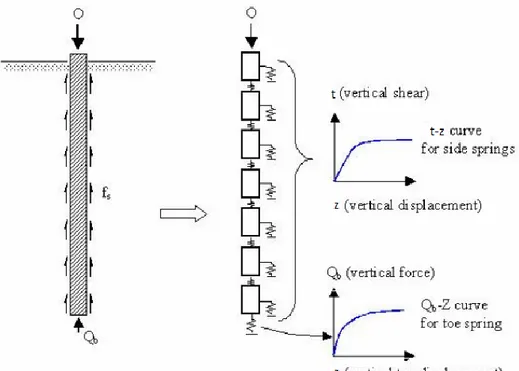
Figure VI.6: Illustration of the idealized model used in t-z load-transfer analyses ... 81
Figure VI.7: Illustration of the t-z curve according to API ... 81
Figure VI.8: t-z curve at X=0.5 m ... 83
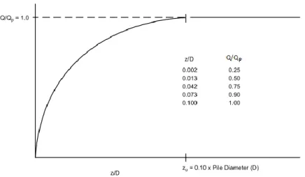
Figure VI.9: Generic pile Tip load - Displacement (Q-z) curve ... 83
Figure VI.10: Q-z curve at depth X=21 m ... 84
Figure VI.11: Settlement vs. pile lengths ... 85
Figure VI.12: Lateral pile resistance vs. pile length (Diameter = 6m) ... 87
Figure VI.13: Total lateral pile resistance (M=1.15) and the design lateral load (5642 kN) ... 87
Figure VI.14: Database for the p-y curve at the depth 6.75 m ... 88
Figure VI.15: p-y curve at the depth 6.75m (layer 5)... 89
Figure VI.16: Results of lateral analysis ... 90
Figure VI.17: Lateral pile head displacement vs. Pile length ... 90
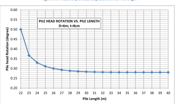
Figure VI.18: Pile head rotation vs. Pile length ... 90
Figure VI.19: Process to calculate the static moment of a segment of hollow circular section... 94
Figure VI.20: Normal stress and shear stress ... 94
Figure VI.21: Parameters to determine static moment in a circular section... 94
Figure VI.22: Internal forces of the 26m long pile ... 95
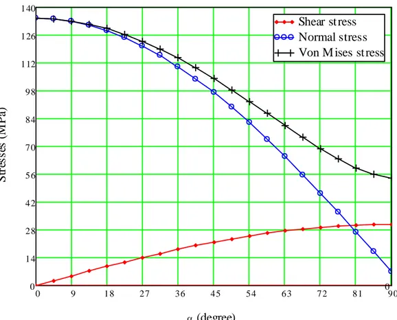
Figure VI.23: Stress distribution of foundation pile at the depth 1.0 m ... 95
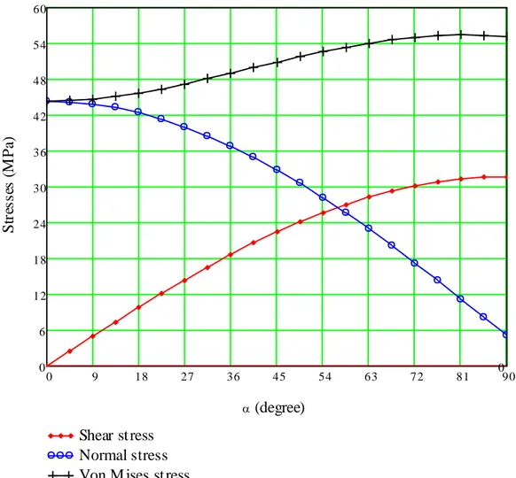
Figure VI.24: Stress distribution of foundation pile at the depth 12.0 m ... 96
Figure VI.25: Stress distribution of foundation pile at the depth 20.0 m ... 97
Figure VI.26: Maximum stresses and utilization ratios along the pile length ... 99
Figure VI.27: The utilization ratio after changing wall thickness ... 100
Figure VI.28: Kinematic model simulates non-gapping behavior ... 102
Figure VI.29: An example of the modified p-y curve for SLS analysis ... 102
Figure VI.30: An example of hysteretic behavior of Link 124 in the model ... 103
Figure VI.31: Wave height of Sea-state 0 in a 10 minute simulation ... 104
Figure VI.32: Wave height of Sea-state 0 in a 100 second simulation ... 104
Figure VI.33: Wave load of Sea-state 0 in a 10 minute simulation (at seabed level) ... 104
Figure VI.34: Wave load of Sea-state 0 in a 100 second simulation (at seabed level) ... 105
Figure VI.35: Wave Spectrum of Sea States ... 105
Figure VI.36: Time domain of Wave and Current Load from Sea State 0 at MSL ... 106
Figure VI.37: Time domain of Wave and Current Load from Sea State 1 at MSL ... 106
Figure VI.38: Time domain of Wave and Current Load from Sea State 2 at MSL ... 106
Figure VI.40: Frequency domain of Wave Load from Sea State 1 at MSL ... 107
Figure VI.41: Frequency domain of Wave Load from Sea State 2 at MSL ... 107
Figure VI.42: Rotation Displacement at tower top – Sea State 1 ... 109
Figure VI.43: PDF of Rotation Displacement at tower top- Sea state 1 ... 109
Figure VI.44: Horizontal Displacement at tower top - Sea State 1 ... 109
Figure VI.45: PDF of Horizontal Displacement at tower top- Sea state 1 ... 110
Figure VI.46: Horizontal Displacement at seabed - Sea State 1 ... 110
Figure VI.47: PDF of Horizontal Displacement at seabed - Sea state 1 ... 110
Figure VI.48: Rotation Displacement at seabed – Sea State 1 ... 111
Figure VI.49: PDF of Rotation Displacement at seabed- Sea state 1 ... 111
Figure VI.50: Behavior of one of the springs during and after the storm – Sea State 1 ... 111
Figure VI.51: Ux of the tower top-single storm ... 112
Figure VI.52: Ux of the tower top-two successive storms ... 112
Figure VI.53: Comparing Ux at the tower top between Single storm and two successive storms ... 112
Figure VI.54: Probability distribution diagram of displacements ... 113
Figure VI.55: Response of structure in spring model – displacement at the tower top ... 114
Figure VI.56: Response of structure in fixed-at-seabed model – displacement at the tower top ... 114
Figure VI.57: Compare the responses of two models at tower top ... 115
Figure VI.58: PSD of Responses at tower top caused by sea state 0 ... 115
Figure VI.59: PSD of Responses at tower top caused by sea state 1 ... 116
Figure VI.60: PSD of Responses at tower top caused by sea state 2 ... 116
Figure VI.61: Calculating models of offshore wind turbine structure ... 117
Figure VI.62: Wave load at sea water level (MSL) ... 117
Figure VI.63: Wave load at seabed level ... 117
Figure VI.64: Horizontal displacement of the tower top in the fixed foundation model ... 118
Figure VI.65: Horizontal displacement of the tower top in the spring foundation model ... 118
Figure VI.66: Normal distribution of horizontal displacements at tower top ... 118
Figure VI.67: Power Spectral Density of horizontal displacements ... 119
Figure VI.68: Result of Ux at the tower top in time domain ... 119
10
List of Tables
Table III.1: Material factors ... 35
Table IV.1: Basic parameters for wind turbine classes ... 47
Table IV.2: Estimations of Effective Fixity Length. (Zaaijer 2002) ... 61
Table V.1: Model of support structure ... 69
Table V.2: Natural frequency of the support structure in EOL OS ... 74
Table V.3: Excitation frequencies ... 75
Table VI.1: Design parameters for axial resistance of driven piles ... 77
Table VI.2: Result of pile settlement calculation ... 85
Table VI.3: Displacement and Rotation of pile head with the length... 90
Table VI.4: Plastified soil zone of the chosen pile ... 92
Table VI.5: Values of stress distribution on the pile section at the depth 20.0 m ... 96
Table VI.6: Internal forces, stresses and utilization of steel strength ... 97
Table VI.7: Sea states for SLS check – taken from 112 states (TEMPEL, 2006) ... 105
Table VI.8: Results of SLS calculations in single storm ... 108
Table VI.9: Parameters of the two normal distributions ... 112
Table VI.10: Linear stiffness of springs ... 114
List of abbreviations
1P Rotation frequency of turbine
3P Blade passing frequency of three-bladed turbine BNWF Beam nonlinear Winkler foundation
FRF Frequency response function
HAT Highest astronomical tide
LAT Lowest astronomical tide
MSL Mean sea level
OWT Offshore wind turbine
RNA Rotor nacelle assembly
SLS Serviceability limit state SSI Soil-structure interaction
ULS Ultimate limit state
List of terms
Blade-passing frequency The frequency at which the blades of a wind turbine pass the tower. Corrosion allowance Extra wall thickness added during design to compensate for any
reduction in wall thickness by corrosion (externally and internally) during design life.
Cut-in speed Minimum wind speed that a wind turbine starts operating
Cut-out speed The wind speed at which the turbine automatically stops the blades from turning and rotates out of the wind to avoid damage to the turbine Fatigue The phenomenon by which a repeated loading and unloading of a
structure causes it various components to gradually weaken and eventually fail.
Nacelle The structure at the top of the wind turbine tower just behind (or in some cases, in front of) the wind turbine blades that houses the key components of the wind turbine, including the rotor shaft, gearbox, and generator.
Splash zone The part of a support structure which is intermittently exposed to seawater due to the action of tide or waves or both.
12
Chapter I. Introduction
1.1. Foundation of offshore wind turbines
“A one hundred yard high tower still has its foundation on the ground”
(Chinese Proverb) All structures, large or small, require adequate foundations. A foundation is defined as that part of the structure that supports the weight of the structure and transmits the load to underlying soil or rock.
Figure I.1: Nysted Offshore Wind Farm
According to Design Standard of Offshore Wind Turbines (BSH, 2007), the overall mechanical system of an offshore wind turbine consists of the components of the turbine and support structure (see Figure I.2). The support structure can be further subdivided into the tower and substructure. The foundation elements form part of the substructure.
Figure I.2: Mechanical system of an offshore wind turbine
As a result of offshore wind turbines development, so far there are four main classes of offshore foundations consist of:
- Piled foundations (Figure I.3, Figure I.4, Figure I.5), - Gravity base foundations (Figure I.4b, Figure I.6), - Skirt and bucket foundations (Figure I.7),
- Floating structures with moored foundations (Figure I.8, Figure I.9).
The piled and gravity base foundations can be further classified into three structural configurations, namely:
- Monopiles, which are designed as piled foundations and exhibit simplicity in fabrication and installation,
- Tripod or quadruped configurations, which can be both piled or gravity based,
14
Figure I.3: a) Standard Monopile Structure, b) Supported Monopile Structure. (DNV-OS-J101 2004)
Figure I.4: a) Tripod Structure, b) Gravity Pile Structure. (DNV-OS-J101 2004)
Figure I.5: Lattice Tower. (DNV-OS-J101 2004)
Figure I.6: Gravity Base Structure. (DNV-OS-J101 2004)
Figure I.7: Suction Bucket Structure (DNV-OS-J101 2004), and b) Installation Principle.
16
Figure I.8: Tension-Leg Platform. (DNV-OS-J101 2004)
Figure I.9: Low-roll Floater. (DNV-OS-J101 2004)
1.2. Design Optimization Project for Offshore Wind Turbines.
It is about two decades since installation of the first offshore wind farm in the early 1990s where there was limited land available for onshore wind energy production. The Vindeby Facility in Denmark (Figure I.10), completed in 1991, has eleven 450 kW turbines that provide a total capacity of about 5 MW. Since then, the trend has been to move wind turbines offshore to take advantage of higher wind speeds; smoother and less turbulent airflow and larger amounts of open space.
However, cost is currently a major inhibitor of offshore wind energy development. It is approximately 50-100% more costly per installed rotor area as compared to conventional onshore projects. The reasons for this are primarily the added complexity of having to install foundations and power cables offshore and secondly the increased costs of the foundation itself. For offshore wind turbines, it is proven that the foundation may account for up to 35% of the installed cost. Hence, optimization of foundation design for offshore wind turbines is crucial for the development of offshore wind farms.
“Optimization of steel monopile offshore wind turbines” project has been carrying out under the cooperation between the ANAST Department (ULg) and Arcelor Mittal Research Center (Walloon
Figure I.10: First offshore wind facility Vindeby in Denmark
Region) in order to develop software named EOL-OS, which is dedicated to the structural optimisation of the support structure based on minimization of production cost or weight. This master thesis is a part of the sub-project named “Design and optimization of the structural foundation of offshore wind turbines”. The general goal of this sub-project is to create an innovative module focusing on the foundation part of offshore wind turbines, which will be integrated in the existing design and optimization chain of the EOL-OS software.
Figure I.11: The interface of the software EOL OS
1.3. Which type of foundation should be chosen?
As mentioned above, there are many types of foundations currently used, depending on geological and environmental conditions, as well as the type of wind turbine. In order to create a module for “Design and optimization of the structural foundation of offshore wind turbines”, all types of offshore foundation should be investigated and designed. However, in the framework of a master thesis, the research will mainly focus on monopile foundations.
1.4. Tasks of the thesis
Having the title: “Design monopile foundations for offshore wind turbines” this thesis will concentrate on design the structure part below water surface of offshore wind turbines, which is called foundation pile (see Figure II.1). The tasks of the thesis seem quite clear:
- To determine the dimensions of the pile basing on ULS and SLS: o Penetration length,
18 o Wall thickness.
- To find the optimized wall thickness of the foundation pile
- To assess the necessity of including foundation part in structure analyses of the whole OWT structure.
1.5. Method to carry out
- Dimensioning the foundation pile will be done by using DET NORSKE VERITAS STANDARD (DNV-OS-J101, 2011).
- After preliminarily having dimensions of the foundation pile, using FEM (SAP200 software) to model the whole structure with plasticity behavior of the soil (nonlinear p-y curves) and carry out time-history analyses to see the behavior of the whole structure under cyclic loading. The stiffness of the foundation will be modified to fulfill requirements of the manufacture in working ability of the turbines.
1.6. Structure of the thesis
The structure of the thesis consists of 7 chapters:
- Chapter 1: Introduce the foundations of offshore wind turbine, the context of the thesis and its tasks.
- Chapter 2: Components of a monopile offshore wind turbine structure, their fabrications and installations.
- Chapter 3: Design methodology. In this chapter design objectives, design process, and design criteria will be explained.
- Chapter 4: Related theories. In this chapter the theories of wind load, wave load, dynamic analysis, and soil model are reviewed.
- Chapter 5: Preliminary design for the chosen offshore wind turbine project. In this chapter all the input information for the chosen offshore wind turbine project will be shown. Design optimization of the tower will be done using EOL-OS software. The output of this chapter is internal forces of the tower at the seabed elevation, which will be used in ultimate limit state design of the foundation pile in the following chapter.
- Chapter 6: Foundation pile design. In this chapter the dimensions of the foundation pile will be determined using ultimate limit state. Afterwards, the suitability of its stiffness will be check using serviceability limit state. Finally, the effect of foundation as well as the p-y curve in the dynamic behavior of the structure will be analyzed.
- Chapter 7: Conclusions and Future works
Chapter II. Support structure of monopile OWTs -
components, fabrication and installation
2.1. Introduction
A general knowledge of foundation piles as well as the whole OWT structure is necessary at the beginning of the pile foundation design. This chapter is devoted to survey main components of an OWT structure, how they are fabricated and their installation.
The contents are divided into four sections. Section 2.2 introduces briefly how an OWT works. As the foundation pile is a part of support structure, all the components of support structure will be surveyed to see their relationships with it in Section 2.3. The next section describes fabrication of foundation pile. Section 2.5 surveys the installation processes of all the components. It is very important when considering stabilities of foundation pile during construction phase.
2.2. How it works?
Once a suitable place for the wind facility is located, piles are driven into the seabed. For each turbine, a tower is installed on the pile foundation for supporting the turbine assembly, for housing the remaining plant components and for providing sheltered access for personnel. A matrix of fiber glass mats impregnated with polyester or epoxy is used for making the rotor blades. The turbine usually consists of a rotor with three blades, connected through the drive train to the generator. After the turbine is assembled, the wind direction sensors turn the nacelle to face into the wind and maximize the amount of energy collected (see Figure II.1). The nacelle is the part that encloses gearbox, generator, and blade hub. The wind moving over the blades makes them
20 rotate around a horizontal hub connected to a shaft inside the nacelle. This shaft, through a gear box, powers a generator to convert the energy into electricity.
2.3. Components of the support structure
2.3.1. DefinitionsThe support structure is made up of three main components: the tower, the substructure and the foundation.
Tower The tubular elements(s) supplied by the turbine manufacturer on top of which the turbine is installed
Substructure The part of the structure extending from the bottom of the tower down to the seabed Foundation The part of the structure in direct contact with the soil, transferring the loads from the
structure to the soil
Refer to Figure II.1, for the monopile support structure, its substructure consists of a transition piece and the above ground part of the foundation pile.
2.3.2. Design elevations
To facilitate communication between different parties involved in the design of an offshore wind turbine, two key elevations must be defined:
- First the interface level is set. The interface level represents the interface between the turbine manufacturer’s responsibility and that of the support structure designer in both a physical and an organizational sense. The interface level is located at the connection between the tower and the substructure. The elevation is chosen such that the main platform, which is generally situated at the level of the flange connection with the tower, cannot be hit by waves under extreme conditions.
- The other elevation that must also be defined is the hub height. The hub height is the elevation at which the hub of the turbine is located.
2.3.3. Support structure components
a. Foundation pile
Foundation piles of a monopile offshore wind turbine are open-ended hollow tubular elements that are installed vertically. Lateral loads are transferred to the soil by activating the horizontal active soil pressure, whereas axial loads are taken by shaft friction and end bearing.
b. Secondary steel items
The substructure usually comprises several secondary items to enable access, export of electricity and for protection of the structure itself. For a monopile support structure, following items will be present:
Boat landings Ladders Platforms
J-tubes Anodes
Boat-landing: The boat-landing is the structure to which a vessel can moor to transfer personnel and equipment to the substructure. The boat-landing consists of two mainly vertical fenders connected by stubs to the main structure. Depending on the environmental conditions and on the maintenance strategy of the operator, there may be one or more boat-landings connected to a support structure.
Ladders: Ladders are required to allow personnel to access the main platform. If the distance to cover is larger than a certain limit, the ladder should be covered by a cage and have facilities for attaching fall arresters. Ladders for access to the main platform are usually combined with the boat-landing to provide protection for transferring personnel and to avoid difficult and dangerous steps to access the ladder from the vessel. Platforms: Platforms are intended as safe working areas for personnel that need to work on the
structure. Different functions can be identified; there are access platforms, resting platforms, and depending on the type of structures service platforms and airtight platforms. Platforms on offshore wind turbines are usually equipped with grating, to prevent excessive (air) pressure build up below the platform due to passing waves and to avoid accumulation of water that would render the floor slippery.
J-tubes: To protect and guide the export cable into the support structure, a J-tube is installed on the structure. The name derives from the shape that the tube makes as it curves to a horizontal orientation near the seabed. J-tubes can be either internal, only to protrude from the substructure at the seabed level, or external.
Anodes: To provide cathodic protection against corrosion, blocks of aluminum may be installed as sacrificial anodes.
2.4. Fabrication
For a monopile support structure the production process for support structures starts with creating the primary elements for the foundation pile and for the transition piece. Sheets of steel produced at a steel mill are delivered at the fabrication yard. Each sheet has been produced to the required dimensions for a particular tubular section.
The edges of plate are beveled in preparation for welding. Subsequently the sheets are rolled into tubular sections. Several tack welds hold the ends of sheet together while the section is further prepared for welding. This includes welding on endplates at both ends of the longitudinal weld to ensure that no impurities end up in the welded joint.
The tubular section is welded at the seam from two sides. Whenever possible the welding is done in an automated process. The welds are ground if required to reduce stress concentrations. Tolerances with respect to out-of-roundness and eccentricities are checked and the quality of the weld is ascertained by nondestructive testing, after which the section is ready for assembly.
22
Figure II.2: Rolling and welding of a foundation pile
The sections are aligned into the predetermined order. Before welding can commence the edges of two adjoining sections are cut into the required weld shape. After preheating the steel surrounding the joint the two sections are welded together. This can be done automatically by rotating the pile while the welding machine remains stationary. Again, welds must be ground and tested.
When all sections are assembled, the primary structure is ready. For the foundation pile it may be required to attach lifting trunnions at the pile top to facilitate upending in the installation phase. Furthermore, when internal J-tubes are applied, holes must be cut in the pile near the seabed level for the tubes to exit. Also, to ensure proper bonding at the grout to steel interface after installation, shear keys may have to be welded at the location of the grout overlap.
Several items are still to be attached to the transition piece. The flange at the transition piece top to which the tower will be bolted is welded on top of the transition piece. Care must be taken to ensure that the transition piece is perfectly round when the flange is attached, as current large diameter structures have a tendency to ovalise under their own weight. Stubs with flanges to which the boat-landings and platforms can be connected at a later stage are welded to the primary structure. Brackets for the attachment of ladders and anodes are also welded onto the structure. The grout skirt at the bottom of the transition piece is attached and supports for the main platform are welded onto the structure. Before the coating can be applied, the surface of the structure is prepared by shot blasting. The structure is subsequently coated in a partly automated process.
Subsequently internal platforms are installed. If the J-tubes are internal, they are installed at this time as well. The J-tubes are not yet extended downwards to their full extent, as the transition pieces are transported upright. The final actions to be performed are the mounting of the main platform, the attachment of the boat-landing, resting platform and ladders and the attachment of a rubber grout seal at the base of the transition piece.
2.5. Installation
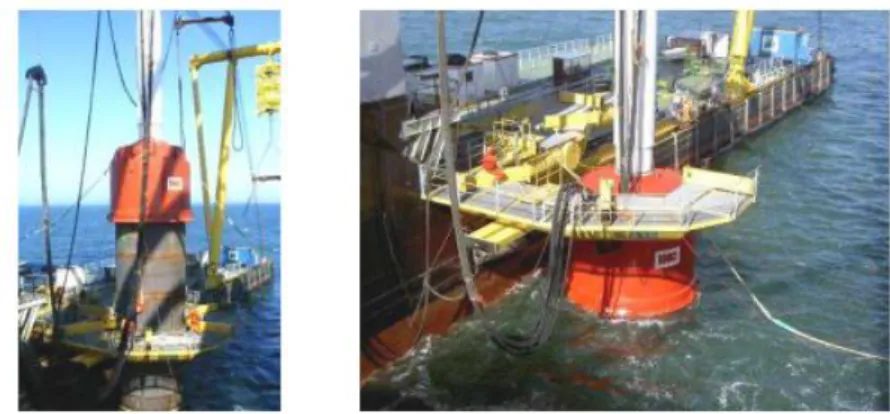
The installation process varies significantly for the different support structure concepts. Monopile foundations may be transported to site by feeder barge, on the installation vessel itself or by floating the piles out to the site. Subsequently the pile must be upended, lifted into position, aligned and driven or drilled into the seabed. The next step is to install the transition piece onto the foundation pile. It is subsequently leveled and fixed by means of grouting the annulus between the pile and transition piece.
The turbine tower is installed, generally in two pieces and bolted. Finally the rotor-nacelle assembly is installed, sometimes with two blades pre-attached and lifting the final blade in place separately or by installing the nacelle first and the pre-assembled rotor later.
In general, the installation procedure of a monopile offshore wind turbine follows the steps as listed below. However, it should be noted that in some cases a slightly different approach may be adopted. For instance, it may be decided that scour protection may not be required. It is also possible to install the nacelle with (some) blades attached.
Foundation pile Scour protection Transition piece Turbine tower Nacelle Rotor/blades a. Foundation pile
Installation of a foundation pile can be done by driving or by drilling.
- Driving
The most common way is to install the pile by driving. The foundation piles are delivered to the offshore site on a barge, usually several at a time. The pile is lifted off the barge using a crane fitted with a lifting tool. The pile is lowered onto the seabed. The weight of the pile will usually cause the pile to penetrate the soil for a few meters. The pile is gripped with an alignment tool at a certain distance above the sea surface to ensure verticality of the pile during driving.
Figure II.3: Pile driving at Offshore Wind Farm Egmond aan Zee
The hammer is lifted onto the pile, after which the pile driving can proceed. If required, driving can continue when the hammer is under water. Usually depth markings are applied to the pile before driving so that the penetration depth can be monitored visually. Driving can be done from a jack-up barge or from a stable floating system, although it should be noted that a floating system is very much dependent on favorable sea conditions.
- Drilling:
When hard soils are encountered, drilling may be the preferred option. A hole is drilled at the desired location using a drilling tool operated from a jack-up barge. The pile can subsequently be inserted in the thus created hole. Alternatively, the pile is placed on the seabed and the drilling tool is
24
Figure II.5: Schematic example of scour protection
inserted in the pile. The hole is drilled through the pile, while the pile is slowly lowered into the newly excavated space. The pile is aligned vertically using an alignment tool. Subsequently the pile is fixed in place by injecting grout into the space between the pile and the soil. During hardening of the grout the pile must be held in place to maintain the vertical alignment. When a foundation pile is installed by means of drilling the appurtenances can be pre-attached directly to the pile. Also the flange to which the turbine can be connected can be attached. In that case there is no need for a transition piece, reducing the number of offshore operations.
b. Scour protection
If a pile is situated in a current, the current is locally increased due to the disturbance in the flow caused by the presence of the pile. In combination with wave action this can cause sand particles to be picked up from the seabed and deposited further downstream. Eventually this can lead to a significant scour hole around the pile. To prevent this scour protection can be applied.
An example of a scour protection design is given in Figure II.5. This is generally in the form of a filter layer of relatively small stones to keep the sand in place on top of which an armor layer is dumped consisting of larger rocks to keep the filter layer in place. The scour protection is installed with the use of dedicated rock-dumping vessels.
With respect to installation two different approaches can be envisaged: static scour protection and dynamic scour protection.
- Static scour protection:
In the case of static scour protection, the filter layer is put in place prior to installation of the foundation pile. The pile is subsequently installed through the filter layer. Once the pile is in place the armor layer is applied. This approach is aimed at preventing the occurrence of a scour hole during the installation process.
- Dynamic scour protection:
When using dynamic scour protection the foundation pile is installed first. Only after the foundation installation is complete the scour protection is installed. Usually the scour protection is installed in one procedure for the entire wind farm. This implies that the installation of the scour protection is commenced once (almost) all of the piles have been installed. In this case it is likely that
a scour hole will develop before the protective rock layers are installed. The scour protection then partially fills the scour hole.
- No scour protection:
Alternatively, it is possible to install an offshore wind farm without any scour protection. In this case the development of a large scour hole is taken into account in the design.
c. Transition piece
The transition piece sits on top of the foundation pile. Its main functions are to provide a flange for the connection of the turbine tower to the foundation, to correct any misalignment of the foundation and to hold the appurtenances, such as the boat-landing, J-tube, ladder and anodes. A platform is located on top of the transition piece. The transition piece can be connected to the foundation in the following three ways: using grout, a flange or slip joint. Transition pieces can be transported to the offshore location by barge along with the foundation piles. Alternatively, they can be carried by the installation vessel.
- Grout connection
This is the most common way to make the connection between the foundation and the superstructure. The transition piece is lifted from the barge and is slid over the top of the foundation pile. Spacers ensure that the required space remains between the pile and the transition piece. Hydraulic jacks are used to align the transition piece vertically. Grout seals close off the bottom of the annulus between pile and transition piece, after which the annulus is filled with grout. After the grout has hardened sufficiently the seals and jacks are removed.
- Flange
The transition piece can also be connected to the foundation pile by means of flanges. The transition piece is lifted into place. Once the flanges are correctly aligned, bolts are used to connect the flanges. This procedure has the advantage that it can be performed quickly. However, great care must be taken o ensure that the flange is not damaged during pile driving.
- Slip joint
A novel way of connecting two tubulars is by means of a slip joint. Both the top of the foundation pile and the bottom of the transition piece have a conical section of which the sides make a small angle with the vertical. The transition piece is lifted onto the foundation pile. Before the transition piece is slid into place, it must be ensured that it is exactly vertical. Once this is achieved the connection can be made by simply lowering the transition piece onto the foundation pile. The friction between the
Figure II.6: Transition piece installation
26 is sufficient to form a reliable connection. The advantage of this connection type is that it is simple to fabricate and allows for rapid installation. However, so far it has not been put to use for offshore wind turbines.
d. Turbine tower
The turbine tower is usually installed in two or three sections which are bolted together. Figure II.7 shows such a tower section being lifted for installation. The connection between the transition piece and the turbine tower is also made by bolting two flanges together.
e. Rotor-nacelle assembly
The rotor-nacelle assembly can be installed either separately or using the Bunny-Ear method. It should be noted that each turbine installation contractor has its preferred method.
- Separate
The nacelle is lifted onto the top of the turbine tower. The flange beneath the yaw bearing of the turbine is bolted to the flange at the tower top when the nacelle is in place, the hub and the blades can be installed. These can be installed in one piece – the rotor assembly as shown in Figure II.8, or separately. The blades are lifted in a frame that allows for easy manoeuvring. With the blade in a vertical position and with the blade root pointing upwards, the blade is carefully positioned in line with its connection point on the hub. The connection is achireved by bolting the blade to a flange in the hub. This procedure is repeated until all blades are connected.
- Bunny-Ear method
In case of a triple bladed turbine two blades can already be attached onshore. These blades protrude upwards at an angle giving the rotor-nacelle assembly an appearance which has led to the method’s distinct name. The advantage is that the rotor-nacelle assembly can be lifted into place with two blades already attached. Only one blade needs to be installed offshore, saving a lot of valuable offshore installation time.
Figure II.7: Lifting of a tower section for installation
28
Chapter III. Design Methodology
3.1. Introduction
In this chapter, the contents are divided into three sections. Section 3.2 emphasizes the design objective of the foundation pile in relation with the support structure. The next section is about the design process for offshore wind turbine support structures. Finally, in Section 3.4, design criteria are defined based on requirements to keep OWTs stable and work efficient.
3.2. Design objective
Before formulating a design objective the context of a support structure should be considered. The support structure can be seen as a part in the larger offshore wind farm development. For the offshore wind farm development the objective is to produce electricity at the lowest possible cost per produced kWh. To achieve this objective the energy yield should be as high as possible, while the costs of the overall development should be as low as possible.
For the individual components, such as the support structure this implies that the costs of the component should be as low as possible, without jeopardizing up-time.
The purpose of a support structure is to hold the wind turbine in place allowing it to produce electricity in a safe and reliable manner, such that the highest possible energy yield can be achieved. Therefore the offshore wind turbine should be able to:
- Withstand all loads during envisaged lifetime
- Remain operable in all intended operational conditions
Furthermore the structure should be able to fulfill all secondary functional requirements, such as accessibility and electricity export, while at the same time posing no threat to the environment and other users of the marine environment.
The objective of the design is therefore to define the geometric and material properties of the support structure, subject to requirements regarding the operability of the wind turbine, load resistance and economics.
3.3. Design process for offshore wind turbine support structures
3.3.1. Design SequenceFigure III.1: Design process for an offshore wind turbine
According to (IEC, 2009) the design process for an offshore wind turbine is as depicted in Figure III.1. This process is defined for a complete offshore wind turbine system, including Rotor Nacelle Assembly (RNA). It assumes that the RNA is designed according to a standard wind turbine class (1) and as such has been type certified by a certification body. Once the design has been initiated (2) for a specific project, the external conditions for the project site must be defined (3). These include site-specific environmental data, local bathymetry, geotechnical information and other relevant oceanographic data. To allow different parties in the project to work with the same data, the
Design initiated (2)
Site-specific external conditions (3)
Design basis for offshore wind turbine
(4)
RNA design (e.g. IEC 61400-1, standard wind turbine class)
(1)
Support structure design (5) RNA design (6)
Design situations and load cases (7)
Load and load effect calculations (8)
Limit state analyses (9)
Structural integrity OK? (10)
30 environmental conditions together with the design criteria for the RNA are recorded in a design basis (4). The design basis itself has to be certified by a certification body.
To be able to apply a type certified turbine at a specific offshore site it must be demonstrated that the RNA still meets the design criteria for the site-specific loads. In the current industry practice the verification of the RNA design (6) will be the responsibility of the wind turbine manufacturer, whereas the support structure design (5) is the responsibility of the support structure designer.
The design process as illustrated in Figure III.1 assumes that the support structure design and verification of the RNA are performed in parallel. Both structures are modeled in structural analysis packages that can account for dynamic response of the structure to external loading. Preferably this entails a fully integrated analysis, but current industry practice also makes use of parallel models in which the interaction between RNA dynamics and the support structure dynamics as well as interactions between aero- and hydrodynamics and the structural response are taken into account.
3.3.2. Design Load Cases
When an initial support structure has been established, a series of Design Load Cases must be defined (7). Different design situations can be identified covering all expected operational situations as well as fault situations. These design situations are defined as follows in the standards for the design of offshore wind turbines (DNV-OS-J101, 2011), (IEC, 2009):
1. Power production
2. Power production plus occurrence of fault 3. Start-up
4. Normal shut-down 5. Emergency shutdown 6. Parked (standing still/idling) 7. Parked and fault conditions
8. Transport, assembly, maintenance and repair
For each of the defined load cases, loads and load effects are calculated (8). This usually entails time domain simulation of the wind and wave loads on a dynamic structural model, including the aero-hydro-servo-elastic behavior of the turbine. The load effects are given by the response of the turbine to these loads in terms of displacements, velocities, accelerations and section forces at the nodes in the structural model.
3.3.3. Limit State Checks
Once the load effects for each of the simulated design load cases have been determined the limit state analyses are performed (9). For different limit states are distinguished:
Ultimate limit state (ULS) Serviceability Limit State (SLS) Accidental Limit State (ALS) Fatigue Limit State (FLS)
The ALS and FLS are sometimes considered part of the ULS analysis.
In the ULS analysis, the structural strength of members and joints as well as the stability of members are checked. Also the strength of the foundation must be verified.
The SLS is related to maximum acceptable deformations of the structure, the foundation and the RNA during operational conditions.
For the ALS the effects of unintended impact loads such as ship impact and impacts due to dropped objects are evaluated.
Finally, the ability of the structure to withstand the combined environmental loading over its intended design life must be verified in the FLS analysis.
The results from these limit state analyses are usually expressed as a utilization ratio, defined as the design load divided by the characteristic resistance. A utilization ratio larger than 1.0 implies that the structure has insufficient resistance to withstand the design load. If the utilizations for all load cases are less than 1.0 the structural integrity is guaranteed (10) and, according to Figure III.1 the design is completed (11). If for some load cases the utilization is larger than 1.0 the structural integrity of the system is not assured and changes to the support structure or the RNA must be made resulting in lower utilizations for the critical load cases. To this end either the loads may be reduced or the resistance of the structure may be increased.
To achieve either load reduction or increased resistance, the support structure design and the RNA design are revised. In some cases the design load cases will have to be redefined, for instance when a more detailed description of the Design Load Cases may lead to less conservative loads and hence lower loads on the structure or RNA. Subsequently the load simulations are performed once again and the limit state checks are executed. This process is repeated until both the support structure and the RNA design meet the design criteria for all considered load cases and for all limit states.
3.3.4. Design evaluation
Figure III.1 considers the design process to be complete when the structural integrity is shown to be satisfied. If this is the only requirement very robust designs may result. Economic considerations should also be taken into account, such that the contribution of the support structure and RNA to the total cost per produced kWh is minimal. Besides checking whether the structural integrity of the structure is guaranteed, it should also be ascertained if further reduction of the overall cost is possible. Primarily this will be achieved by reducing the mass of the structure, thereby reducing the overall material costs. However, it should also be verified that reducing the mass of the support structure does not introduce unforeseen costs in other parts of the structure or for fabrication installation and maintenance issues. To reflect the economic considerations the process shown in Figure III.1 should be updated to include a check for the minimum structure mass and costs. If the structural mass can be further reduced the dimensions should be changed and the structural integrity should be checked again. Only when the mass of the structure can be reduced no further without compromising the structural integrity the design may be considered completed.
32
3.4. Design criteria
3.4.1. From requirements to criteria
In Section 3.2 the design objective is formulated as defining the geometric and material properties of the support structure subject to requirements regarding the operability of the wind turbine, load resistance and economics, thereby allowing safe, reliable and economical operation of the wind farm. To assess the suitability of the support structure design, it should fulfill certain design criteria. These criteria are related to the requirements for the wind turbine and for the support structure itself. For the wind turbine the following requirements are considered:
- The turbine should be situated at a certain elevation above the sea surface, for effective electricity production and to ensure sufficient safety
- The electricity produced by the generator must be fed into the electricity grid. For this purpose provisions for the exporting of the electricity must be incorporated.
- To allow reliable operation the turbine must regularly undergo maintenance and repair. Therefore provisions must be present for accessing the turbine.
- Sufficient clearance between the blades and the support structure must be maintained to reduce loads on the turbine and to avoid collision of the blades with the structure.
- To avoid damage to components in the wind turbine the tower head motions should be within predefined limits.
The support structure should ensure that all aforementioned requirements are fulfilled. Furthermore the structural integrity of the support structure must be guaranteed. Therefore the support structure must be able to withstand all loads from the wind turbine and from the environment onto itself and to transfer these loads to the soil.
To satisfy these requirements criteria can be formulated regarding natural frequencies, strength and deformations. In the following sections these criteria are discussed for the main components making up the overall support structure: tubular members, joints and foundation elements. Also requirements and criteria with regard to fabrication and installation are put forward.
3.4.2. Natural frequencies
Natural frequencies of the support structure are very important as they determine the dynamic behavior of the offshore wind turbine. If the frequency of excitation is near a natural frequency, resonance occurs and the resulting response will be larger than in the quasi-static case. This leads to higher stresses in the support structure and, more importantly to higher stress ranges, an unfavorable situation with respect to the fatigue life of the offshore wind turbine. Therefore it is important to ensure that the excitation frequencies with high energy levels do not coincide with a natural frequency of the support structure.
In the case of an offshore wind turbine excitation is due to both wind and waves. For fatigue considerations sea states with a high frequency of occurrence have the largest effect. These are
generally relatively short waves with a significant wave height
H
sof around 1 m to 1.5 m and a zero-crossing periodT
zof around 4 s to 5 s.The wind excitation frequencies that should be avoided are those that coincide with the range of rotational frequencies of the rotor. This will be illustrated for the chosen 7MW turbine which will be used during subsequent stages of this project. With a minimum rotational speed at the cut-in wind speed of 4(1/min) and a maximum rotational speed of 14.2(1/min), the rotational frequency interval ranges from 0.067 Hz to 0.237 Hz. This interval is indicated with 1P. Furthermore, the blade-passing frequency interval should also be avoided. This interval, indicated with 3P for a triple bladed turbine is equal to the rotational frequency interval times the number of blades, this value ranges from 0.2 Hz to 0.71 Hz.
3.4.3. Strength criteria
Yielding
Stresses in elements must remain below the yield stress for metallic materials. Wind loads, wave loads, gravity and inertia loads and pressure differences between inside and outside of element (hoop stresses) all contribute to the acting stress in the element.
Buckling may occur before the full yield capacity of a cross section is reached. For foundation piles, buckling is generally not considered a critical failure mode as the pile is normally supported by the soil on both the inside and outside. Pile strength should be checked under extreme compression loads. Buckling
For monopiles the wall thickness can vary along the length of the pile as the bending moment increases from the top of the tower toward the seabed due to hydrodynamic and aerodynamic loading and then decreases as load is gradually transferred to the soil.
The wall thickness should be sufficient to prevent buckling. Two forms of buckling can be identified: global or beam buckling and local or sheet buckling. In the case of global buckling the structure collapses in its entirety, whereas in the case of local buckling the buckling occurs only locally. However, the occurrence of local buckling may initiate global buckling. The most important parameters in the buckling analysis are:
The buckling length, which is different for local and global buckling, The normal force in the structure or element under consideration, The bending moment in the structure or element under consideration, A slenderness parameter
The outcome of the buckling check is a usage factor, which indicates to what extent the cross section is utilized with respect to the buckling capacity. This value can be used to optimize the wall thickness. Furthermore, the top of the pile usually requires a large wall thickness to cope with the high
34 stresses due to pile driving. The pile toe is usually also dimensioned with a larger wall thickness to prevent buckling during pile driving.
Fatigue
As the support structure is subjected to continuous load variations, the fatigue of the structure needs to be checked. Preferably all load combinations of wind and waves with their directions are incorporated in this check. But as the number of load cases is usually very large, it is desirable to use a reduced number of load cases. This can be achieved by two methods, preferably simultaneously. The first is by assuming that all loads act in the same direction. This approach is conservative as it leads to an accumulation of fatigue damage in a single location on the circumference of the pile. This is only valid in the power production state. For idling states (non-power producing states with unlocked rotor) wind-wave misalignment may result in higher loads than when wind and waves are aligned. The main reason for this is the lack of aerodynamic damping. Idling situations occur below cut-in and above cut-out but may also occur within the range of power production, due to non-availability of the wind turbine due to turbine errors. Therefore, the portion of idling state simulations must consider wind-wave misalignment for the fatigue analysis of the support structure, especially for monopiles.
In reality, the fatigue damage is lower than estimated by the first method, as the damage is spread over multiple locations on the circumference. In the second method, all the environmental states in a wind speed bin are grouped. The corresponding
H
sandT
zare associated with the state within the wind speed bin with the largest probability of occurrence.The probability of occurrence of the grouped state is the summed probability of all contributing states. Sometimes it may be more realistic to group the environmental states in a wind speed bin into two or more grouped states. Either way, the resulting number of environmental states that serve as input for the fatigue analysis is significantly reduced.
For each of these environmental states a time domain simulation is performed and the bending stresses in the support structure are recorded. Near the welds, where there are discontinuities in the structure, the local stress should be multiplied by an appropriate stress concentration factor. Using a stress cycle counting method, the number of cycles in each stress range bin is counted. With this information and using an S-N curve corresponding to the weld detail under consideration the fatigue damage due to environmental loads can be determined. Furthermore, fatigue damage due to transient events such as start-up and shutdown procedures and fatigue damage due to pile driving should be included in assessing the total fatigue damage.
3.4.4. Design criteria for monopile foundations
For geotechnical design of monopile foundations, both the ultimate limit state and the serviceability limit state shall be considered.