Pépite | Minimisation de la consommation d'énergie pour des taches temps-réels parallèles sur des architectures multicoeurs hétérogènes
120
0
0
Texte intégral
(2) Thèse de Houssam-Eddine Zahaf, Lille 1, 2016. i. “Life is short and you can not realize If you start a job you have to finalize worthy, life is not what someone did or does Sometimes your life is too many lies and too many shames you have exercise So never be late to tell your apologize Cause life is short and you can not realize Life is something and you should matter So start by making it little bit better Every thing is simple, An alphabet starts with one letter And even one hundred miles starts with one meter It is not hard, Try to speak, or send a letter Cause, life is short and it does matter A lot of people where there for me from the day I took my first breath, and they are still in my life, some has been gone, but they are still as memories, others enter and they are making memories, Thank You, ” Houssam Eddine ZAHAF. © 2016 Tous droits réservés.. lilliad.univ-lille.fr.
(3) Thèse de Houssam-Eddine Zahaf, Lille 1, 2016. ii. Acknowledgements The research lead in this thesis is the property of both University of Lille1, and University of Oran 1. The works that will be presented has been done in two research teams: Optimization dans les Reseaux de Transport Et Systemes Embarques (ORTESE) team of the laboratory “Laboratoire d’Architetures Paralleles, Embarquees et du Calcul Intensif” LAPECI of university of Oran 1 and, emeraude team of “Centre de Recherche en Informatique, Signal et Automatique de Lille” CRIStAL laboratory of university of Lille. The research were held at IRCICA, “Institut de Recherche en Composants logiciels et materiels pour l’Information et la Communication Avancee” and LAPECI laboratory. This research has been funded in part by IRCICA and PHC Curien under the direction of Abou El Hassen BENYAMINA and Richard OLEJNIK. Giuseppe LIPARI has participated in directing the thesis and has importatnt impact on the choices taken during the last two years. I am very glad and grateful to my directors Hassan and Richard with a very special thank and admiration to Giuseppe LIPARI for his scientific and human support. ¨ Goossens and Benyattou Mohamed I would thank also the member of my jury. Firstly, Joel for accepting and putting time even in their very full agenda, to read and evaluate my work. I thank also Sophie Quinton, Samira Chouraqui and Lebbah Yahia to be members of my jury and accept to examine the research presented in this disseration. I will always remember the great times that I have passed in Emeraude and ORTESE teams. I will always keep in my memories Philippe Devienne, Pierre Boulet, Clement Balabriga, Pierre Falez, Yassine SidLakhdar, Loukil Lakhdar, Abbassia Deba, Aroui Abdelkader, · · · . A special thank to Antoine Bertout for discussions that we had about everything and nothing, and the great moment that we shared in playing football. A special thank to all IRCICA and IRI colleagues, Anne So, Ahmed, Xavier lepallec and all the people that I could not cite all names. A special thought to my family, My Father Charef and my both mothers, the one who gave me life and to the one that made me the man I am today. A special thank to my brothers: Farida, Ismail, Salah, Oum Elkhier, Nassima, Hanane, Wafaa, Rajaa, my nephews, and to my friends, especially mohammed maloufi, Azzouz Joseph and Amrane Kichou. A very special thought to Sawsen, the woman that made my life different. Thank you for being there, you are a treasure for me.. © 2016 Tous droits réservés.. lilliad.univ-lille.fr.
(4) Thèse de Houssam-Eddine Zahaf, Lille 1, 2016. 1. Abstract by Houssam-Eddine ZAHAF Cyber physical systems (CPS) and Internet of Objects (IoT) are generating an unprecedented volume and variety of data that needs to be collected and stored on the cloud before being processed. By the time the data makes its way to the cloud for analysis, the opportunity to trigger a reply might be late. One approach to solve this problem is to analyze the most time-sensitive data at the network edge, close to where it is generated. Thus, only the pre-processed results are sent to the cloud. This computation model is know as *Fog Computing* or *Edge computing*. Critical CPS applications using the fog computing model may have real-time constraints because results must be delivered in a pre-determined time window. Furthermore, in many relevant applications of CPS, the processing can be parallelized by applying the same processing on different sub-sets of data at the same time by the mean parallel programming techniques. This allow to achieve a shorter response time, and then, a larger slack time, which can be used to reduce energy consumption. In this thesis we focus on the problem of scheduling a set of parallel tasks on multicore processors, with the goal of reducing the energy consumption while all deadlines are met. We propose several realistic task models on architectures with identical and heterogeneous cores, and we develop algorithms for allocating threads to processors, select the core frequencies, and perform schedulability analysis. The proposed task models can be realized by using OpenMPlike APIs.. © 2016 Tous droits réservés.. lilliad.univ-lille.fr.
(5) Thèse de Houssam-Eddine Zahaf, Lille 1, 2016. 2. Contents Acknowledgements. ii. Abstract. 1. Introduction. 11. I. Context, Motivations & Related work. 14. 1. Multiprocessors & Parallel Systems 1.1 Introduction . . . . . . . . . . . . . . . . . . . . . . . . 1.1.1 Classification of multicore systems . . . . . . . 1.2 Programming parallel architecture . . . . . . . . . . . 1.2.1 Thread & Process . . . . . . . . . . . . . . . . . 1.2.2 Sources of parallelism . . . . . . . . . . . . . . 1.2.3 Communication models . . . . . . . . . . . . . 1.2.4 Decomposition & granularity of a parallel task 1.2.5 Limits and costs of parallel programming . . . 1.3 Parallel models . . . . . . . . . . . . . . . . . . . . . . 1.3.1 Fork-Join model . . . . . . . . . . . . . . . . . . 1.3.2 Gang Model . . . . . . . . . . . . . . . . . . . . 1.4 Designing a parallel code . . . . . . . . . . . . . . . . 1.5 Power consumption in multiprocessor systems . . . . 1.5.1 DVFS: Dynamic voltage and frequency scaling 1.5.2 DPM: Dynamic Power Management . . . . . . 1.6 Conclusion . . . . . . . . . . . . . . . . . . . . . . . . .. 2. . . . . . . . . . . . . . . . .. Introduction to real-time systems 2.1 Introduction . . . . . . . . . . . . . . . . . . . . . . . . . 2.2 Task Model . . . . . . . . . . . . . . . . . . . . . . . . . . 2.3 Priority Driven Scheduling . . . . . . . . . . . . . . . . 2.3.1 Scheduling characteristics . . . . . . . . . . . . . 2.4 Uniprocessor Scheduling . . . . . . . . . . . . . . . . . . 2.4.1 Rate Monotonic RM . . . . . . . . . . . . . . . . 2.4.2 Deadline Monotonic DM . . . . . . . . . . . . . 2.4.3 Earliest Deadline First . . . . . . . . . . . . . . . 2.5 Multiprocessor Scheduling . . . . . . . . . . . . . . . . . 2.5.1 Partitioned Scheduling . . . . . . . . . . . . . . . 2.5.2 Global Scheduling . . . . . . . . . . . . . . . . . 2.5.3 Semi-Partitioned . . . . . . . . . . . . . . . . . . 2.6 Programming Real-time systems . . . . . . . . . . . . . 2.6.1 Real-time Scheduling policies In LINUX Kernel 2.6.2 POSIX Threads . . . . . . . . . . . . . . . . . . . 2.7 Conclusion . . . . . . . . . . . . . . . . . . . . . . . . . .. © 2016 Tous droits réservés.. . . . . . . . . . . . . . . . . . . . . . . . . . . . . . . . .. . . . . . . . . . . . . . . . . . . . . . . . . . . . . . . . .. . . . . . . . . . . . . . . . . . . . . . . . . . . . . . . . .. . . . . . . . . . . . . . . . . . . . . . . . . . . . . . . . .. . . . . . . . . . . . . . . . . . . . . . . . . . . . . . . . .. . . . . . . . . . . . . . . . . . . . . . . . . . . . . . . . .. . . . . . . . . . . . . . . . . . . . . . . . . . . . . . . . .. . . . . . . . . . . . . . . . . . . . . . . . . . . . . . . . .. . . . . . . . . . . . . . . . . . . . . . . . . . . . . . . . .. . . . . . . . . . . . . . . . . . . . . . . . . . . . . . . . .. . . . . . . . . . . . . . . . . . . . . . . . . . . . . . . . .. . . . . . . . . . . . . . . . . . . . . . . . . . . . . . . . .. . . . . . . . . . . . . . . . . . . . . . . . . . . . . . . . .. . . . . . . . . . . . . . . . . . . . . . . . . . . . . . . . .. . . . . . . . . . . . . . . . .. 15 16 16 19 19 20 21 21 21 22 22 23 23 24 24 24 25. . . . . . . . . . . . . . . . .. 26 27 27 28 29 30 30 31 32 34 34 35 35 36 37 37 37. lilliad.univ-lille.fr.
(6) Thèse de Houssam-Eddine Zahaf, Lille 1, 2016. 3 3. Parallel Real-time: Related work 3.1 CPS Systems Needs . . . . . . . . . . . . . . . . . . . . . . . . 3.1.1 Real-time needs . . . . . . . . . . . . . . . . . . . . . . 3.1.2 Parallel computing needs . . . . . . . . . . . . . . . . 3.1.3 CPS and energy consumption . . . . . . . . . . . . . . 3.2 This work . . . . . . . . . . . . . . . . . . . . . . . . . . . . . 3.2.1 Global or Partitionned? . . . . . . . . . . . . . . . . . 3.2.2 What kind of parallelism to do and where? . . . . . . 3.2.3 What energy saving techniques are we going to use? 3.3 Related work . . . . . . . . . . . . . . . . . . . . . . . . . . . . 3.3.1 Taxonomy on parallel real-time tasks . . . . . . . . . 3.3.2 OpenMP . . . . . . . . . . . . . . . . . . . . . . . . . . 3.4 Parallel Real-time tasks & scheduling . . . . . . . . . . . . . 3.4.1 Gang Model . . . . . . . . . . . . . . . . . . . . . . . . 3.4.2 Multithread Model . . . . . . . . . . . . . . . . . . . . 3.4.3 Federated scheduling . . . . . . . . . . . . . . . . . . 3.5 Related work to energy consumption . . . . . . . . . . . . . . 3.6 Conclusion . . . . . . . . . . . . . . . . . . . . . . . . . . . . .. II 4. 5. . . . . . . . . . . . . . . . . .. . . . . . . . . . . . . . . . . .. . . . . . . . . . . . . . . . . .. . . . . . . . . . . . . . . . . .. . . . . . . . . . . . . . . . . .. . . . . . . . . . . . . . . . . .. . . . . . . . . . . . . . . . . .. . . . . . . . . . . . . . . . . .. . . . . . . . . . . . . . . . . .. . . . . . . . . . . . . . . . . .. . . . . . . . . . . . . . . . . .. . . . . . . . . . . . . . . . . .. Contributions FTC on Uniform cores 4.1 Introduction . . . . . . . . . . 4.2 System overview . . . . . . . 4.3 Architecture Model . . . . . . 4.4 Task model . . . . . . . . . . . 4.5 Power & Energy Models . . . 4.5.1 Power Model . . . . . 4.5.2 Energy Model . . . . . 4.6 Allocation and Scheduling . . 4.6.1 Exact Scheduler . . . . 4.6.2 FTC Heuristic . . . . . 4.7 Experimentation . . . . . . . . 4.7.1 Task Generation . . . . 4.7.2 Simulations . . . . . . 4.7.3 Results & discussions 4.8 Conclusion . . . . . . . . . . .. 50 . . . . . . . . . . . . . . .. . . . . . . . . . . . . . . .. . . . . . . . . . . . . . . .. . . . . . . . . . . . . . . .. . . . . . . . . . . . . . . .. . . . . . . . . . . . . . . .. . . . . . . . . . . . . . . .. . . . . . . . . . . . . . . .. . . . . . . . . . . . . . . .. allocating CPM tasks to heterogeneous platforms 5.1 Introduction . . . . . . . . . . . . . . . . . . . 5.2 System Model . . . . . . . . . . . . . . . . . . 5.2.1 Experimental platform . . . . . . . . . 5.2.2 Architecture Model . . . . . . . . . . . 5.2.3 Model of the execution time . . . . . . 5.2.4 Parallel moldable tasks . . . . . . . . . 5.2.5 Power model . . . . . . . . . . . . . . 5.2.6 Energy model . . . . . . . . . . . . . . 5.3 Allocation & Scheduling . . . . . . . . . . . . 5.3.1 Optimal schedulers . . . . . . . . . . . 5.3.2 Scheduling heuristics . . . . . . . . . . 5.3.3 Frequency selection . . . . . . . . . . . 5.3.4 CP partitioning . . . . . . . . . . . . .. © 2016 Tous droits réservés.. 39 40 40 40 41 41 41 42 42 44 44 44 45 45 46 48 48 49. . . . . . . . . . . . . . . . . . . . . . . . . . . . .. . . . . . . . . . . . . . . . . . . . . . . . . . . . .. . . . . . . . . . . . . . . . . . . . . . . . . . . . .. . . . . . . . . . . . . . . . . . . . . . . . . . . . .. . . . . . . . . . . . . . . . . . . . . . . . . . . . .. . . . . . . . . . . . . . . . . . . . . . . . . . . . .. . . . . . . . . . . . . . . . . . . . . . . . . . . . .. . . . . . . . . . . . . . . . . . . . . . . . . . . . .. . . . . . . . . . . . . . . . . . . . . . . . . . . . .. . . . . . . . . . . . . . . . . . . . . . . . . . . . .. . . . . . . . . . . . . . . . . . . . . . . . . . . . .. . . . . . . . . . . . . . . . . . . . . . . . . . . . .. . . . . . . . . . . . . . . . . . . . . . . . . . . . .. . . . . . . . . . . . . . . . . . . . . . . . . . . . .. . . . . . . . . . . . . . . . . . . . . . . . . . . . .. . . . . . . . . . . . . . . . . . . . . . . . . . . . .. . . . . . . . . . . . . . . . . . . . . . . . . . . . .. . . . . . . . . . . . . . . . . . . . . . . . . . . . .. . . . . . . . . . . . . . . . . . . . . . . . . . . . .. . . . . . . . . . . . . . . . . . . . . . . . . . . . .. . . . . . . . . . . . . . . .. 51 52 52 52 52 53 53 54 54 54 55 60 60 60 61 62. . . . . . . . . . . . . .. 63 64 64 64 65 65 69 70 73 74 74 76 78 78 lilliad.univ-lille.fr.
(7) Thèse de Houssam-Eddine Zahaf, Lille 1, 2016. 4 5.4. . . . . . .. . . . . . .. . . . . . .. . . . . . .. . . . . . .. . . . . . .. . . . . . .. . . . . . .. . . . . . .. . . . . . .. . . . . . .. . . . . . .. . . . . . .. . . . . . .. . . . . . .. . . . . . .. . . . . . .. . . . . . .. . . . . . .. . . . . . .. . . . . . .. 82 82 83 86 89 89. Parallel Di-graph model 6.1 Introduction . . . . . . . . . . . . . . . . . . . . 6.2 Some related work . . . . . . . . . . . . . . . . 6.3 System Model . . . . . . . . . . . . . . . . . . . 6.3.1 Architecture model . . . . . . . . . . . . 6.3.2 Task Model . . . . . . . . . . . . . . . . 6.4 Parallel applications . . . . . . . . . . . . . . . 6.4.1 MPEG encoding/decoding . . . . . . . 6.4.2 Array-OL . . . . . . . . . . . . . . . . . 6.5 Schedulability analysis . . . . . . . . . . . . . . 6.5.1 Decomposition . . . . . . . . . . . . . . 6.5.2 Analysis . . . . . . . . . . . . . . . . . . 6.6 Heuristics . . . . . . . . . . . . . . . . . . . . . 6.6.1 Task decomposition & thread allocation 6.7 Results and Discussions . . . . . . . . . . . . . 6.7.1 Task Generation . . . . . . . . . . . . . . 6.7.2 Simulations . . . . . . . . . . . . . . . . 6.7.3 Scenario 1 . . . . . . . . . . . . . . . . . 6.7.4 Scenario 2 . . . . . . . . . . . . . . . . . 6.8 Conclusion . . . . . . . . . . . . . . . . . . . . .. . . . . . . . . . . . . . . . . . . .. . . . . . . . . . . . . . . . . . . .. . . . . . . . . . . . . . . . . . . .. . . . . . . . . . . . . . . . . . . .. . . . . . . . . . . . . . . . . . . .. . . . . . . . . . . . . . . . . . . .. . . . . . . . . . . . . . . . . . . .. . . . . . . . . . . . . . . . . . . .. . . . . . . . . . . . . . . . . . . .. . . . . . . . . . . . . . . . . . . .. . . . . . . . . . . . . . . . . . . .. . . . . . . . . . . . . . . . . . . .. . . . . . . . . . . . . . . . . . . .. . . . . . . . . . . . . . . . . . . .. . . . . . . . . . . . . . . . . . . .. . . . . . . . . . . . . . . . . . . .. . . . . . . . . . . . . . . . . . . .. . . . . . . . . . . . . . . . . . . .. . . . . . . . . . . . . . . . . . . .. . . . . . . . . . . . . . . . . . . .. 90 91 91 92 92 92 94 94 94 98 98 99 102 102 103 104 106 106 108 109. 5.5 6. Results and discussions 5.4.1 Task Generation . 5.4.2 Simulations . . . 5.4.3 Scenario 1 . . . . 5.4.4 Scenario 2 . . . . Conclusion . . . . . . . .. . . . . . .. . . . . . .. . . . . . .. . . . . . .. . . . . . .. . . . . . .. . . . . . .. . . . . . .. . . . . . .. . . . . . .. . . . . . .. . . . . . .. Conclusion & Perspactives. 110. Personal publications. 112. Bibliography. 113. © 2016 Tous droits réservés.. lilliad.univ-lille.fr.
(8) Thèse de Houssam-Eddine Zahaf, Lille 1, 2016. 5. Contents. © 2016 Tous droits réservés.. lilliad.univ-lille.fr.
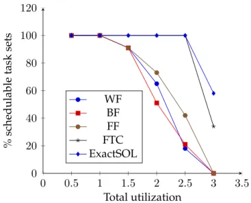
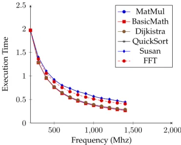
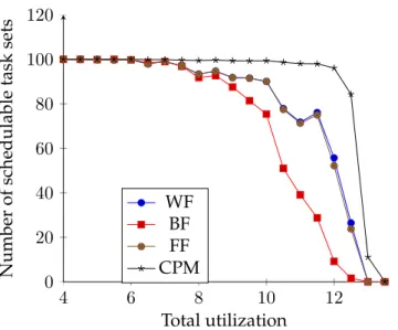
(9) Thèse de Houssam-Eddine Zahaf, Lille 1, 2016. 6. List of Figures 1.1 1.2 1.3 1.4 1.5 1.6 1.7. The power & heat increasing Shared memory model . . . . Distributed memory model . Hybrid memory model . . . . Example of Data parallelism . Example of task parallelism . Example of Fork-Join Model .. . . . . . . .. . . . . . . .. . . . . . . .. . . . . . . .. . . . . . . .. . . . . . . .. . . . . . . .. . . . . . . .. . . . . . . .. . . . . . . .. . . . . . . .. . . . . . . .. . . . . . . .. . . . . . . .. . . . . . . .. . . . . . . .. . . . . . . .. . . . . . . .. . . . . . . .. 16 18 18 18 20 20 23. 2.1 2.2 2.3 2.4 2.5 2.6. Periodic Task model . . . . . . . . . . . . . . . . . Example of scheduling with rate monotonic . . . . Example of scheduling with Deadline Monotonic Example of scheduling with EDF . . . . . . . . . . Demand Bound Function . . . . . . . . . . . . . . Partitioned Scheduling vs Global Scheduling . . .. . . . . . .. . . . . . .. . . . . . .. . . . . . .. . . . . . .. . . . . . .. . . . . . .. . . . . . .. . . . . . .. . . . . . .. . . . . . .. . . . . . .. . . . . . .. . . . . . .. . . . . . .. . . . . . .. . . . . . .. . . . . . .. 28 31 32 33 33 34. 3.1 3.2 3.3 3.4 3.5 3.6. Comparaison between static and dynamic energy in different technologies The memory power dissipation by one little and big core . . . . . . . . . . Difference between Gang and Co scheduling . . . . . . . . . . . . . . . . . Fork-join Model . . . . . . . . . . . . . . . . . . . . . . . . . . . . . . . . . . Generalized Model of Saifullah . . . . . . . . . . . . . . . . . . . . . . . . . Multi-Phase Multi-Thread Model . . . . . . . . . . . . . . . . . . . . . . .. . . . . . .. . . . . . .. . . . . . .. . . . . . .. 43 43 45 46 47 48. 4.1 4.2 4.3 4.4. An example of excess − time evaluation . . . . . . . . . . . . . . . . . . . . Schedulability rate for BF, WF, FF, FTC and Exact Scheduler . . . . . . . . Average Utilization per cores for BF, WF, FF, FTC and the exact scheduler Energy consumption for different heuristics . . . . . . . . . . . . . . . . . .. . . . .. . . . .. . . . .. . . . .. 57 61 62 62. 5.1 5.2. The execution time of the 6 benchmarks when allocated on one little/big Core . . The execution time of square matrix multiplication (200x200) thread allocated on one little/big Core . . . . . . . . . . . . . . . . . . . . . . . . . . . . . . . . . . . . Execution time of the MATMUL (150x150) thread with and without interfering thread . . . . . . . . . . . . . . . . . . . . . . . . . . . . . . . . . . . . . . . . . . . . The computed mt as a function of RSS . . . . . . . . . . . . . . . . . . . . . . . . . The execution time of matrix multiplication under several decompositions . . . . The execution time of different task decompositions at different frequencies . . . The memory power dissipation by one little and big core . . . . . . . . . . . . . . Power dissipation of matrix multiplication on big and little cores . . . . . . . . . Power dissipation for different processing . . . . . . . . . . . . . . . . . . . . . . . Real-values and regressions of power dissipation of little cores of matrix multiplication and Fourier transformations . . . . . . . . . . . . . . . . . . . . . . . . . Energy consumption matrix multiplication and Fourier transformations threads allocated on little and big cores . . . . . . . . . . . . . . . . . . . . . . . . . . . . . The number of schedulable task sets . . . . . . . . . . . . . . . . . . . . . . . . . . Average utilization per each core group . . . . . . . . . . . . . . . . . . . . . . . . Scenario 1: Selected Frequency for big and little cores . . . . . . . . . . . . . . . . Energy consumption for big and little cores . . . . . . . . . . . . . . . . . . . . . .. 66. 5.3 5.4 5.5 5.6 5.7 5.8 5.9 5.10 5.11 5.12 5.13 5.14 5.15 © 2016 Tous droits réservés.. . . . . . . .. . . . . . . .. . . . . . . .. . . . . . . .. . . . . . . .. . . . . . . .. . . . . . . .. . . . . . . .. . . . . . . .. . . . . . . .. . . . . . . .. 66 67 68 68 69 71 71 72 72 73 86 86 87 88 lilliad.univ-lille.fr.
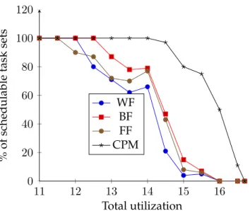
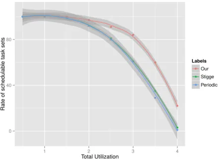
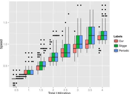
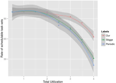
(10) Thèse de Houssam-Eddine Zahaf, Lille 1, 2016. 7 5.16 The number of schedulable task sets . . . . . . . . . . . . . . . . . . . . . . . . . . 6.1 6.2 6.3 6.4 6.5 6.6 6.7 6.8 6.9 6.10 6.11 6.12. © 2016 Tous droits réservés.. Example of parallel di-graph task. . . . . . . . . . . . . . . . . . . . . . . . . . A di-graph modeling MPEG encoding . . . . . . . . . . . . . . . . . . . . . . . An Example of video filter with Array OL . . . . . . . . . . . . . . . . . . . . . The radar tracking applications with Array-OL . . . . . . . . . . . . . . . . . . Radar tracking application with our model . . . . . . . . . . . . . . . . . . . . 1st Scenario: Schedulability Rate . . . . . . . . . . . . . . . . . . . . . . . . . . 1st Scenario: Schedulability Rate . . . . . . . . . . . . . . . . . . . . . . . . . . 1st Scenario: Average Speed (All) as function of total utilization . . . . . . . . 1st Scenario: Average Speed (Only Schedulable) as function of total utilization 2st Scenario: Schedulability Rate . . . . . . . . . . . . . . . . . . . . . . . . . . 2st Scenario: Average Speed (Only Schedulable) as function of total utilization 2st Scenario: Energy Consumption as a function of total utilization . . . . . .. . . . . . . . . . . . .. . . . . . . . . . . . .. 89 93 94 96 96 97 104 106 107 107 108 108 109. lilliad.univ-lille.fr.
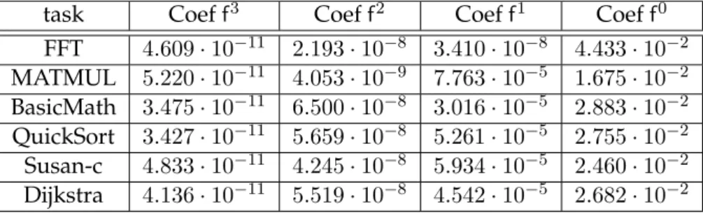
(11) Thèse de Houssam-Eddine Zahaf, Lille 1, 2016. 8. List of Tables 2.1 2.2 2.3. Example of Rate Monotonic:Task set details . . . . . . . . . . . . . . . . . . . . . . Example of Deadline monotonic: Task set details . . . . . . . . . . . . . . . . . . . The used Pthread primitives and their role . . . . . . . . . . . . . . . . . . . . . .. 30 32 38. 3.1. Comparaison between global and partitioned scheduling . . . . . . . . . . . . . .. 42. 4.1 4.2 4.3 4.4. Example of excess-time evaluation . . . . . . . . . . Excess-time values . . . . . . . . . . . . . . . . . . . Example of FTC scheduling: task set details . . . The results of task allocation . . . . . . . . . . . . .. . . . .. . . . .. . . . .. . . . .. . . . .. . . . .. . . . .. . . . .. . . . .. . . . .. . . . .. . . . .. . . . .. . . . .. . . . .. 56 57 58 59. 5.1 5.2 5.3 5.4. Cut-points list example . . . . . . . . . . . . . . . . . . . . The power dissipation coefficients for the 6 benchmarks . Example of cut-point selection : cut-point details . . . . . Example of cut-point selection: the selected results . . . .. . . . .. . . . .. . . . .. . . . .. . . . .. . . . .. . . . .. . . . .. . . . .. . . . .. . . . .. . . . .. . . . .. . . . .. 70 73 81 81. 6.1 6.2 6.3. An example of a task modeled by a parallel di-graph . . . . . . . . . . . . . . . . An example of a path set . . . . . . . . . . . . . . . . . . . . . . . . . . . . . . . . . The decomposition according to [val] = 6 of task of Figure 6.1 . . . . . . . . . . .. 93 98 98. © 2016 Tous droits réservés.. . . . .. . . . .. . . . .. lilliad.univ-lille.fr.
(12) Thèse de Houssam-Eddine Zahaf, Lille 1, 2016. 9. List of Symbols % random(a, b) fj f sj τi Ji,a Ai,a Di Oi Ti T Tj act A Th aTH Ci C. The rest of the ecludienne division generates a random number between a and b The operating frequency of core j An arbitrary operating frequency The speed of core j Task i The ath job of task τi The arrival time of ath instance of task τi The relative deadline of task τi The offset of task τi The period of task τi A task set The task set allocated on core j The active state of an arbitrary core A multicore architecture An arbitrary thread An arbitrary allocated thread Execution time of the single thread version of task τi The execution time of an arbitrary thread. Ci,j Thi,j tdbf(τi , t) dbf(Tj , t) Di dbf α. The execution time of the thread of task τi allocated to core j in FTC model The thread of task τi that is allocated to core j in the FTC task model The demand bound function of task τi for an interval of time of length t The demand bound function of task set Tj for an interval of time of length t An arbitrary decomposition of task τi The demand bound function The symbol of excess time in equations. Thi,j,k aTHi,j,k,z ugi,k,z (fop ) ξ~ γi,k ctgi,j,k (fop ) ct Gg mtgi,k,z mt Ωg Sg. Thread k of cut-point γi,j of task τi Thread Thi,j,k allocated on core j The base line utilization of thread Thi,k,z when allocated on group g Energy coeficients The k th cut-point of task τi A part of execution time of thread Thi,k,z on group g operating at frequency fop An arbitrary part of the execution time that depends on the frequency the group g of cores The memory acces time of thread Thi,k,z on group g An arbitrary memory acces time The needed strength of group g The current strength of core g. Πi (t) pC |Si | pdf pdf(i, j). All pathes that could be generated by task τi in any interval of time of length t The combination of p elements of |Si | elements An arbitrary path demand function The demand function of the j th path of task τi. © 2016 Tous droits réservés.. lilliad.univ-lille.fr.
(13) Thèse de Houssam-Eddine Zahaf, Lille 1, 2016. 10 πki (t) G(V, E) Ei e(s, d) vi,j Vi g Ci,j,k (fop ) v Ci,k (f). © 2016 Tous droits réservés.. the k th path of task τi of length t A di-graph of vertices set V and edges E The egdes set of the graph of task τi in the di-graph model The edge starting from s and ending at d The vertice j of task graph of τi The vertice set of the task graph of τi The worst case execution time of thread Thi,k,z on group g The execution time of vertice vi,j on a core operating at f. lilliad.univ-lille.fr.
(14) Thèse de Houssam-Eddine Zahaf, Lille 1, 2016. 11. Introduction Context The internet of things (IoT) is a network of physical devices, vehicles, buildings and other embedded items with electronics, software, sensors, and network connectivity that enables these objects to collect and exchange data. The IoT allows objects to be sensed and controlled remotely across existing network infrastructure, creating opportunities for more direct integration of the physical world into computer-based systems, and resulting in improved efficiency, accuracy and economic benefit. When IoT is augmented with sensors and actuators, the technology becomes an instance of the more general class of cyber-physical systems (CPS) (please refer to Baheti and Gill, 2011). A CPS is therefore a system composed of physical entities such as mechanisms controlled or monitored by computer-based algorithms. Today, a precursor generation of cyber-physical systems can be found in areas as diverse as aerospace, automotive, chemical processes, civil infrastructure, energy, health-care, manufacturing, transportation, entertainment, and consumer appliances. CPS is generating an unprecedented volume and variety of data, by the time the data makes its way to the cloud for analysis, the opportunity to trigger a reply might be late. The basic idea is to analyze the most time-sensitive data at the network edge, close to where it is generated instead of sending vast amounts of data to the cloud. The reply can be triggered quick enough to ensure the system constraints. Only, the pre-processing results are sent later to the cloud for historical analysis and longer-term storage. Thus, a CPS should (Cisco, 2015): • Minimize latency: Milliseconds matter when you are trying to prevent manufacturing line shutdowns or restore electrical service. Analyzing data close to the device that collected the data can make the difference between averting disaster and a cascading system failure. • Conserve network bandwidth: Offshore oil rigs generate 500 GB of data weekly. Commercial jets generate 10 TB for every 30 minutes of flight. It is not practical to transport vast amounts of data from thousands or hundreds of thousands of edge devices to the cloud. Nor is it necessary, because many critical analyses do not require cloud scale processing and storage. • Operate reliably: CPS data is increasingly used for decisions affecting citizen safety and critical infrastructure. The integrity and availability of the infrastructure and data cannot be in question. This computing model is known as Fog Computing or Edge computing (see Bonomi et al., 2012). Fog computing uses one or a collaborative multitude of near-user edge devices to carry out a substantial amount of storage, communication, and control, configuration, measurement and management. The embedded platforms used for supporting fog computing are often multicore systems and many of CPS applications can be easily parallelized by distributing data across the parallel computing elements. Reducing power consumption in these systems is a very serious problem especially when processing elements operate on battery power. Even when they are connected to the electric grid, we need to keep the consumption as low as it is possible. Multicore technology can help us in achieving timeliness and low power consumption systems. In fact, even © 2016 Tous droits réservés.. lilliad.univ-lille.fr.
(15) Thèse de Houssam-Eddine Zahaf, Lille 1, 2016. 12 when the computational load is not very high, multicore processors are more energy efficient than an equivalent single-core platform as reported by Wolf, 2012. Critical processings done in CPS systems such as electrical grid control must deliver responses in a pre-determined time window. Thus, a large spectrum of CPS applications realtime applications. Therefore, in this thesis we will be interested in parallelizing real-time application to multiprocessor architectures in the goal of reducing the energy consumption.. Contributions In this thesis, we will be interested in particular in parallelization techniques, real-time scheduling techniques, energy reduction techniques for a set of real-time tasks expressed with different models on several types of multicore architectures. Mainly our contributions consist in proposing realistic and expressive task models and efficient feasibility tests for these task models on multicore architectures. Based on the proposed tests, we propose methodologies to reduce the energy consumption for identical, uniform and heterogeneous cores. Thus the main contributions of this thesis are: 1. The Free-To-Cut FTC task model, 2. The allocation of FTC tasks to uniform architectures: exact and sufficient feasibility tests, 3. The Cut-point task model (CPM), 4. A methodology to build a realistic timing, power and energy models 5. The allocation of cut-point tasks to heterogeneous multicore architectures: exact and sufficient feasibility tests, 6. Modelling parallel task with di-graphs, 7. The allocation of di-graph parallel tasks to identical cores platform: a sufficient feasibility test.. Organization This thesis is structured as follows. In the first chapter, we give a quick overview on multicore systems, parallel programming and energy consumption techniques. In this chapter, we illustrate how parallel systems are seen for non-real-time systems. The second chapter will be reserved to real-time systems theory, and practice. This chapter is divided mainly into two parts: in the first, we talk mainly on real-time systems scheduling theory, and in the second part, we will show how a simple real-time task model can be implemented in a real-time operating system. We will talk later in chapter 3 about the context of our work and the motivations that pushed us to be interested in the parallelization of real-time task on multicore architecture, and we will state some work that has been done in this field of research in real-time systems. In the chapter 4, we present a simple and non-realistic parallel real-time task model that we call, Free-To-Cut task model. We propose a corresponding feasibility test, and exact scheduler and a heuristic to allocate such tasks to a uniform multicore architecture. The chapter 5, will be reserved into an extension of the model in chapter 4, to a realistic model. In addition, we will be interested on allocating a set of task of the extended model to heterogeneous multicore platform. In this chapter, we present the results of a large set of experiments that has been conducted on an ARM big.LITTLE processor to build task, architecture and energy models. We propose an other feasibility test for these tasks on heterogeneous architectures. We will show that obtaining an optimal solution of these problem is hard for only medium size problem, and © 2016 Tous droits réservés.. lilliad.univ-lille.fr.
(16) Thèse de Houssam-Eddine Zahaf, Lille 1, 2016. 13 we will propose heuristics that allows to obtain quasi-optimal solutions in a reasonable time. In the last chapter, we present a very expressive parallel task model that extend the di-graph the one proposed by Stigge et al., 2011. We propose a sufficient feasibility test for the extended model to a set of identical cores.. © 2016 Tous droits réservés.. lilliad.univ-lille.fr.
(17) Thèse de Houssam-Eddine Zahaf, Lille 1, 2016. 14. Part I. Context, Motivations & Related work. © 2016 Tous droits réservés.. lilliad.univ-lille.fr.
(18) Thèse de Houssam-Eddine Zahaf, Lille 1, 2016. 15. Chapter 1. Multiprocessors & Parallel Systems “ On dit que le temps change les choses, mais en fait le temps ne fait que passer et nous devons changer les choses nous-młmes. ” Andy Warhol. Contents 1.1. Introduction . . . . . . . . . . . . . . . . . . . . . . . . . . . . . . . . . . . . . . . 16 1.1.1 Classification of multicore systems . . . . . . . . . . . . . . . . . . . . . . 16. 1.2. Programming parallel architecture . . . . . . . . . . . . . . . . . . . . . . . . . . 19. 1.3. Thread & Process . . . . . . . . . . . . . . . . . . . . . . . . . . . . . . . . 19. 1.2.2. Sources of parallelism . . . . . . . . . . . . . . . . . . . . . . . . . . . . . 20. 1.2.3. Communication models . . . . . . . . . . . . . . . . . . . . . . . . . . . . 21. 1.2.4. Decomposition & granularity of a parallel task . . . . . . . . . . . . . . . 21. 1.2.5. Limits and costs of parallel programming . . . . . . . . . . . . . . . . . . 21. Parallel models . . . . . . . . . . . . . . . . . . . . . . . . . . . . . . . . . . . . . 22 1.3.1. Fork-Join model . . . . . . . . . . . . . . . . . . . . . . . . . . . . . . . . . 22. 1.3.2. Gang Model . . . . . . . . . . . . . . . . . . . . . . . . . . . . . . . . . . . 23. 1.4. Designing a parallel code . . . . . . . . . . . . . . . . . . . . . . . . . . . . . . . 23. 1.5. Power consumption in multiprocessor systems . . . . . . . . . . . . . . . . . . 24. 1.6. © 2016 Tous droits réservés.. 1.2.1. 1.5.1. DVFS: Dynamic voltage and frequency scaling . . . . . . . . . . . . . . . 24. 1.5.2. DPM: Dynamic Power Management . . . . . . . . . . . . . . . . . . . . . 24. Conclusion . . . . . . . . . . . . . . . . . . . . . . . . . . . . . . . . . . . . . . . 25. lilliad.univ-lille.fr.
(19) Thèse de Houssam-Eddine Zahaf, Lille 1, 2016. Chapter 1. Multiprocessors & Parallel Systems. 1.1. 16. Introduction. Gordon E. Moore, the co-founder of Intel and Fair-child Semiconductor observed, in 1965, that the number of transistors in a dense integrated circuit is doubling every year in the number of components per integrated circuit, and projected this rate of growth would continue for at least another decade. In 1975, looking forward to the next decade, he revised the forecast to doubling every two years. This observation is called the moore’s law (please refer to Aspray, 2004, Moore, 2006, Moore, 2005). In the last decade, Intel stated that the pace of advancement has slowed. Starting from 2004, the market leaders have difficulties of satisfying Moores law greedy demand for computing power using classic single processor architectures because increasing the operating clock speed improvements slowed due to the serious heating problems and considerable power consumption (see Figure 1.1) and also due to the increasing gap between processor and memory speeds. This, in effect, pushes cache sizes to be larger in order to mask the latency of memory. This helps only to the extent that memory bandwidth is not the bottleneck in performance, the increasing difficulty of finding enough parallelism in a single instruction stream to keep a high-performance single-core processor busy.. F IGURE 1.1: The power & heat increasing. In order to continue performance improvements, processor manufacturers such as Intel and AMD have turned to multicore designs. the idea is to put several computing elements on the same die and operate these cores on lower frequencies. A multicore processor is a single computing component with more than one computing element (referred as “cores”). Manufacturers integrate cores onto a single integrated circuit. In contrast to multicore systems, the term multiprocessors refers to multiple physically separate processing-units.. 1.1.1. Classification of multicore systems. Multicore processors have been pervading and several architectures of multicore systems had been proposed. For example, cores may or may not share caches, and they may implement message passing (MPI itemplementations 2016) or shared-memory inter-core communication (such as OpenMP Architecture Review Board, 2008). At the same time, cores may run same instructions or different ones. Cores may be interconnected by a single bus, ring, two-dimensional © 2016 Tous droits réservés.. lilliad.univ-lille.fr.
(20) Thèse de Houssam-Eddine Zahaf, Lille 1, 2016. Chapter 1. Multiprocessors & Parallel Systems. 17. mesh, and crossbar, · · · . According to a criteria (Instruction set, memory, micro-architectures, · · · ), multicore (multiprocessor) systems can be classified to distinguish between them. According to Flynn Flynn, 1972 classification of architectures is based upon the number of instructions that could be run at the same time (single, multiple), and on the data streams on which instructions are applied (also single, multiple). Hence, 4 classes can be distinguished: • Single Instruction, Single Data (SISD): Also known as the Von Neumann machine, or sequential computer. In this class no parallelism is allowed, only one instruction is run at the time. A single control unit fetches a single instruction from memory. However, SISD machines can have concurrent processing characteristics. Pipelined processors and superscalar processors are common examples found in most modern SISD computers (Michael, 2003). • Single Instruction, Multiple Data (SIMD): In such architectures, the same instruction can be applied to different data at the same time. In January 8, 1997, Intel proposed the 1st processor with MMX technology, The Pentium MMX (P166MX) operating at frequency 166 Mhz (P166MX) is the first SIMD machine. • Multiple Instruction, Single Data (MISD) Multiple instructions operate on the same data stream. It is very uncommon architecture and only few cases can use this kind of machines. • Multiple Instruction, Multiple Data (MIMD) Multiple processing elements simultaneously executing different instructions on different data. This class is the more general than all previous classes. All architectures, we use in this thesis, are from this class of multicore architectures. An example of MIMD system is Intel Xeon Phi, descended from Larrabee microarchitecture. These processors have multiple processing cores (up to 61 as of 2015) that can execute different instructions on different data (Pfister, 2008). According to architecture and microarchitecture According (as state in Davis and Burns, 2011) to the difference (architecture and micro-architecture) between the computing elements, the multiprocessors (multicores) can be classified to: • Identical: The processors are identical; hence the execution time of a processing is the same on all processors. The odroid C2 contains an identical core platform compound of 4 ARM cortex A53 processors (HardKernel, 2016). • Uniform: The rate of execution of a processing depends only on the speed of the processor. Thus, a processor of speed ×2, will execute a processing at twice of the rate of a processor of speed 1. The third generation of Intel i5 can be considered as a unifrom architecture (Intel, 2016). • Heterogeneous: The processors are different; hence the rate of execution of a processing depends on both the processor and the task. Indeed, not all tasks may be able to execute on all processors and a processing may have different execution rates on two different processors operating at the same speed. The single ISA platforms such ARM big.LITTLE allow to have the same instruction set architecture in all cores, but with different microarchitecture and architecture, thus allowing a task to be executed on any core. SAMSUNG EXYNOS 5422 is a Single ISA platform compound of 8 cores: 4 “big” cores ARM A15, and 4 little cores ARM A7 (Samsung, 2016).. © 2016 Tous droits réservés.. lilliad.univ-lille.fr.
(21) Thèse de Houssam-Eddine Zahaf, Lille 1, 2016. Chapter 1. Multiprocessors & Parallel Systems. 18. F IGURE 1.2: Shared memory model. In Chapter 4, we will be interested in uniform architectures, and in single ISA architectures, especially SAMSUNG EXYNOS 5422 processor in Chapter 5. In last chapter, we will be restricted to only identical core platforms. According to memory architecture • Shared memory A shared memory multicore (multiprocessor) offers a single memory space used by all processors. Any processors can access physically to data at any location in the memory (see Figure 1.2). • Distributed memory refers to a multicore (multiprocessor) in which each processor has its own private memory. Processings can only operate physically on local data, and if remote data is required, the processing must communicate with one or more remote processors (see Figure 1.3).. F IGURE 1.3: Distributed memory model. • hybrid memory refers to a multiprocessor in which each core has its own private memory, and all cores share a global memory. The largest and fastest computers in the world today employ both shared and distributed memory architectures (see Figure 1.4). In the experiments that we present in chapter 5, we will be restricted to a platform with a shared memory.. F IGURE 1.4: Hybrid memory model. © 2016 Tous droits réservés.. lilliad.univ-lille.fr.
(22) Thèse de Houssam-Eddine Zahaf, Lille 1, 2016. Chapter 1. Multiprocessors & Parallel Systems. 1.2. 19. Programming parallel architecture. Parallel computing is a type of computation in which many calculations are carried out simultaneously, operating on the principle that large problems can often be divided into smaller ones, which are then solved at the same time. There are several different forms of parallel computing: bit-level, instruction-level, data, and task parallelism. Parallelism has been employed for many years, mainly in high-performance computing, but interest in it has grown lately due to cyber-physical systems. Parallel computing is closely related to concurrent computing, they are frequently used together, and often conflated, though the two are distinct: it is possible to have parallelism without concurrency (such as bit-level parallelism), and concurrency without parallelism (such as multitasking by time-sharing on a single-core CPU). In some cases parallelism is transparent to the programmer, such as in bit-level or instruction-level parallelism, but explicitly parallel algorithms, particularly those that use concurrency, are more difficult to write than sequential ones, because concurrency introduces several new classes of potential software bugs, of which race conditions are the most common. Communication and synchronization between the different subtasks are typically some of the greatest obstacles to getting good parallel program performance. Before talking in more details about programming parallel architectures, we give a quick overview on two fundamental concepts in parallel computing: Threads and Processes.. 1.2.1. Thread & Process. First, we will give basic definitions of process, thread and how a real-time task is implemented a like thread. A process is an instance of a computer program that is being executed. Each process has a Process Control Block (PCB) which contains information about that process. Depending on the implementation of PCB in OS1 , PCB may hold different pieces of information, commonly it contains: • PID: Process Identifier • PPID the Parent Process Identifier; • UID: User Identifier; • The values of registers: The current state of the process even if it is ready, running, of blocked; • Instruction Pointer (IP) or Program counter (PC): it contains the address of the next instruction to execute; • Process addressing space; PCB may contains other information like the processor time, register values, · · · . A thread is the smallest sequence of instructions that can be managed independently by a scheduler. The implementation of threads and processes differs between operating systems, but in most cases a thread is a component of a process. If a process has only one thread, the thread is executed in sequential (single thread). If the process contains multiple threads, they execute concurrently and share resources such as memory. On uniprocessor systems, the CPU is switched between multiple threads/processes. When a thread/process execution is interrupted from a higher priority task, all information about the interrupted task are saved, and the information of the new one is loaded, this operation is called Context Switch. 1. Operating Systems. © 2016 Tous droits réservés.. lilliad.univ-lille.fr.
(23) Thèse de Houssam-Eddine Zahaf, Lille 1, 2016. Chapter 1. Multiprocessors & Parallel Systems. 20. Array A. ... ... do i= 1,25 A(i)=B(i)*3 end do ... .... ... ... do i= 26,50 A(i)=B(i)*3 end do ... .... ... ... do i= m,n A(i)=B(i)*3 end do ... .... Task 1. Task 2. Task 3. F IGURE 1.5: Example of Data parallelism. ... .... ... .... Code of Task One ... .... Task 1. ... .... Code of Task Two ... .... Task 2. Code of Task Three ... .... Task 3. if (processor=”a”) Task 1 if (processor=”b”) Task 2 if (processor=”C”) Task 3. Main Thread. F IGURE 1.6: Example of task parallelism. 1.2.2. Sources of parallelism. Data Parallelism Data parallelism is a form of parallelization, it focuses on distributing the data across different parallel computing nodes. Data parallelism is achieved when each processor performs the same processing on different subsets of data at the same time. In Figure 1.5, we present an example of data parallelism. Tasks task 1, task 2, · · · , task n do the same computation is done on a sub array of Array B and results are gathered in Array A. Task Parallelism Task parallelism (control parallelism) focuses on distributing different processing across different processors. The processings may execute the same or different code. It is of a paramount importance to consensus on programming models because the existence of different parallel computers, thereby facilitating portability of software. Parallel programming models are a bridge between hardware and software. Classifications of parallel programming models can be divided broadly into two areas: process interaction and problem decomposition. First, we will focus on the interaction between tasks.. © 2016 Tous droits réservés.. lilliad.univ-lille.fr.
(24) Thèse de Houssam-Eddine Zahaf, Lille 1, 2016. Chapter 1. Multiprocessors & Parallel Systems. 1.2.3. 21. Communication models. Process interaction relates to the mechanisms by which parallel processes are able to communicate with each other. The most common forms of interaction are shared memory and message passing. Shared memory model Shared memory is an efficient means of passing data between processes. In a shared-memory model, parallel processes share a global address space that they read and write to asynchronously. Asynchronous concurrent access can lead to race conditions and mechanisms such as locks, semaphores and monitors can be used to avoid these. Conventional multi-core processors directly support shared memory, which many parallel programming languages and libraries, such as Cilk (Blumofe et al., 1996), OpenMP(OpenMP Architecture Review Board, 2008) and Threading Building Blocks, (TBB Pheatt, 2008), are designed to exploit. Message passing In a message-passing model, parallel processes exchange data through passing messages to one another. These communications can be asynchronous, where a message can be sent before the receiver is ready, or synchronous, where the receiver must be ready.. 1.2.4. Decomposition & granularity of a parallel task. Granularity is the amount of real work in the parallel task. If granularity is too fine, then performance can suffer from communication overhead. If granularity is too coarse, then performance can suffer from load imbalance. The granularity of a multithreaded application greatly affects its parallel performance. When decomposing an application for multithreading, one approach is to logically partition the problem into as many parallel tasks as possible. Within the parallel tasks, next determine the necessary communication in terms of shared data and execution order. Since partitioning tasks, assigning the tasks to threads, and sharing data between tasks are not free operations, one often needs to agglomerate, or combine partitions, to overcome these overheads and achieve the most efficient implementation. The agglomeration step is the process of determining the best granularity for parallel tasks. The granularity is often related to how balanced the work load is between threads. While it is easier to balance the workload of a large number of smaller tasks, this may cause too much parallel overhead in the form of communication, synchronization, etc. Therefore, one can reduce parallel overhead by increasing the granularity (amount of work) within each task by combining smaller tasks into a single task.. 1.2.5. Limits and costs of parallel programming. Here, we present the challenges that programmer could face in the world of parallel programming: • Acceleration Amdahl’s law gives the theoretical speedup in latency of the execution of a task at fixed workload that can be expected of a system whose resources are improved. Amdahl’s law can be formulated as: Slatency (s) =. 1 (1 − p) +. p s. (1.1). where: – Slatency is the theoretical speedup in latency of the execution of the whole task; © 2016 Tous droits réservés.. lilliad.univ-lille.fr.
(25) Thèse de Houssam-Eddine Zahaf, Lille 1, 2016. Chapter 1. Multiprocessors & Parallel Systems. 22. – s is the speedup in latency of the execution of the part of the task that benefits from the improvement of the resources of the system; – p is the percentage of the execution time of the whole task concerning the part that benefits from the improvement of the resources of the system before the improvement. ( Slatency (s) ≤. 1 1−p. lims→∞ Slatency (s) =. 1 1−p .. (1.2). Furthermore, the above equation show that the theoretical speedup of the execution of the whole task increases with the improvement of the resources of the system and that regardless the magnitude of the improvement, the theoretical speedup is always limited by the part of the task that cannot benefit from the parallelization. Amdahl’s law is often used in parallel computing to predict the theoretical speedup when using multiple processors. For example, if a program needs 20 hours using a single processor core, and a particular part of the program which takes one hour to execute cannot be parallelized, while the remaining 19 hours (p = 0.95) of execution time can be parallelized, then regardless of how many processors are devoted to a parallelized execution of this program, the minimum execution time cannot be less than that critical one hour. Hence, the theoretical speedup is limited to at most 20 times (1/(1 p) = 20). For this reason parallel computing is relevant only for a low number of processors and very parallelizible programs. • Communication In the general case, different threads communicate with each another as they execute. Communication usually takes place by passing data from one thread to another as part of a workflow. • Harder to debug Programming multi-threaded code often requires complex coordination of threads and can easily introduce subtle and difficult-to-find bugs due to the interweaving of processing on data shared between threads. Consequently, such code is much more difficult to debug than single-threaded code when it fails. • Load Balancing workload across processors can be problematic, especially if they have different performance characteristics. • Complexity In general, parallel processing are much more complex than corresponding sequential processing. • Portability: Thanks to standardization in several APIs such as MPI, POSIX threads and OpenMP, portability issues with parallel programs are not as serious as in past years. However, even though standards exist for several APIs, implementations differ in a number of details, sometimes requiring code modifications to ensure the portability.. 1.3. Parallel models. In this section, we present two models for parallel programming, the fork-joint model and the gang model and their correspondent schedulers.. 1.3.1. Fork-Join model. The forkjoin model is a way of executing parallel programs, such that execution branches alternatively between parallel and sequential execution at designated points in the program. Parallel sections may fork recursively until a certain task granularity is reached. © 2016 Tous droits réservés.. lilliad.univ-lille.fr.
(26) Thèse de Houssam-Eddine Zahaf, Lille 1, 2016. Chapter 1. Multiprocessors & Parallel Systems. S1. p11. p12. S2. 23. p21. S3. p22. p23 F IGURE 1.7: Example of Fork-Join Model. The fork join example given in Figure 1.7 presents an example of three consecutive forks and joins. The first sequential segment is S1 which forks two parallel threads P11 and P12 . The second sequential segment is S2 and it joints the two segments forked by S1 and continue onward its execution and it forks at its turn three parallel threads P21 , P22 and P23 . The last task joins the threads created by S2 and continue onward till the task ends. Threads used in forkjoin programming will typically have a work stealing scheduler that maps the threads onto the underlying thread pool. This scheduler can be much simpler than a fully featured, preemptive operating system scheduler: general-purpose thread schedulers must deal with blocking for locks, but in the fork join paradigm, threads only block at the join point. Fork-join is the main model of parallel execution in the OpenMP framework. although OpenMP implementations may or may not support nesting of parallel sections. It is also supported by the Java concurrency framework, the Task Parallel Library for .NET, and Intel’s Threading Building Blocks (TBB).. 1.3.2. Gang Model. When a critical section is used by some thread which is descheduled because its time quantum expired, then other threads attempting to access the critical section must wait until the context switch. A solution is to execute the threads of the same parallel application in parallel at the same time. Thus, task should synchronize activation, running and termination of all its threads. This scheme is called “Gang scheduling”.. 1.4. Designing a parallel code. Managing concurrency acquires a central role in developing parallel applications. The basic steps in designing parallel applications are: 1. Partitioning: The partitioning stage of a design is intended to expose opportunities for parallel execution. Hence, the focus is on defining a large number of small tasks in order to yield what is termed a fine-grained decomposition of a problem. 2. Communication: The tasks generated by a partition are intended to execute concurrently but cannot, in general, execute independently. The computation to be performed in one task will typically require data associated with another task. Data must then be transferred between tasks to allow computation to proceed. This information flow is specified in the communication phase of a design.. © 2016 Tous droits réservés.. lilliad.univ-lille.fr.
(27) Thèse de Houssam-Eddine Zahaf, Lille 1, 2016. Chapter 1. Multiprocessors & Parallel Systems. 24. 3. revisiting: In the third stage, development moves from the abstract toward the concrete. Developers revisit decisions which has been made during the partitioning and communication phases in so that the task will execute efficiently on some class of parallel architectures. The fine-grain decompositions can be clustered to gather to form bigger tasks and provide a smaller number of tasks. 4. Mapping: In the fourth and final stage of the design of parallel algorithms, the developers specify where each task will be executed. In this thesis, we are interested in the two last aspects for parallel programming design under real-time constraints in the goal of reducing the energy consumption. Hence, in the next section, we overview two major techniques for reducing the power consumption : DVFS and DPM.. 1.5. Power consumption in multiprocessor systems. Reducing power consumption in multicore systems for CPS is a very serious problem when they are operated by batteries. Even when they are connected to the electric grid, we need to keep the consumption as low as it is possible. In fact, even when the computational load is not very high, multicore processors are more energy efficient than an equivalent single-core platform Wolf, 2012. Previously, power management on multicore architectures boils down to a simple principle “turn-off anything you do not use” in the logic of Dynamic Power Management (DPM). In modern processor, it is possible to change dynamically the operating frequency to reduce the power consumption, this operation is called Dynamic Voltage and Frequency Scaling DVFS.. 1.5.1. DVFS: Dynamic voltage and frequency scaling. Increasing the frequency of a processor involves switching its transistors more rapidly, and transistors that are switched more rapidly dissipate more power. The power dissipated due to switching is called dynamic power. Dynamic Voltage and Frequency Scaling (DVFS) describes the use of two power saving techniques: dynamic frequency scaling and dynamic voltage scaling. The benefit of scaling voltage and frequency is to reduce power consumption of the processor and the attached peripherals like memory. A frequency can be set on one of several available operating points. An Operating Point is a set voltage and frequency in which the processor can operate. Typically, the voltage is determined by the minimum voltage that can sustain a set processor frequency, therefore it usually does not make sense to have two different operating points at the same frequency, but at different voltages. Downscaling the frequency downgrades the timing performances of a system. Thus, calibrating the frequency to reduce the energy consumption is always coupled with a quality of service.. 1.5.2. DPM: Dynamic Power Management. Even transistors that are not switching will still leak current during idle periods. This leakage current constantly dissipates power. The amount of power dissipated due to leakage current is called static power. In 1996, Intel, HP, and Microsoft with Toshiba and Phoenix standardized static power management by presenting the ACPI Specification. ACPI defines which registers, piece of hardware should be available, and what information should be offered to control the processor states. The basic idea behind ACPI based power management is that unused/less used devices should be put into lower power states. Even the entire system can be set into low-power state (sleeping state) when possible. Standards designate two famillies of processor states: P-states and Cstates. P-states are described as performance states; each P-state corresponds to a certain clock © 2016 Tous droits réservés.. lilliad.univ-lille.fr.
(28) Thèse de Houssam-Eddine Zahaf, Lille 1, 2016. Chapter 1. Multiprocessors & Parallel Systems. 25. speed and voltage. P-states could also be called processing states, contrary to C-states, a core in a P-state is actively processing instructions. With the exception of C0, C-states correspond to sleep/idle states, there is no processing on a core when it is in a C-state. The ACPI standard only defines 4 CPU power states from C0 to C3: C0 is the state where the P-state transitions happen: the processor is processing. C1 halts the processor. There is no processing done but the processor’s hardware management determines whether there will be any significant power savings. All ACPI compliant CPUs must have a C1 state. C2 is optional, also known as stop clock. While most CPUs stop ”a few” clock signals in C1, most clocks are stopped in C2. C3 is also known as sleep, or completely stop all clocks in the CPU. The actual result of each ACPI C-state is not defined. It depends on the power management hardware that is available on the processor. Modern processors does not only stop the clock in C3, but also move to deeper sleep states C4/C5/C6 and may drop the voltage of the CPU. The total power dissipation is the sum of the dynamic and static power. The integral of dissipated power over time defines the energy consumption. In this work, we focus on minimizing the total energy dissipation. In this thesis, several hardware architectures will be benchmarked to build a timing and power profile for both DVFS and DPM techniques.. 1.6. Conclusion. In this chapter, we presented an overview on two fundamental concepts that we are going to use in this thesis: The parallelization techniques and energy saving techniques. We will be interested in the next chapters in particulary two problems of parallelization: decomposition and allocation. We will consider a set of tasks with timing constraints to be parallelized to a multicore platform with the goal of reducing the energy consumption. However before that we will give a quick overview on real-time systems in the next chapter.. © 2016 Tous droits réservés.. lilliad.univ-lille.fr.
(29) Thèse de Houssam-Eddine Zahaf, Lille 1, 2016. 26. Chapter 2. Introduction to real-time systems “ Time is like a sword Either you strike it, or it will strike you ” Arabic proverbe. Contents 2.1. Introduction . . . . . . . . . . . . . . . . . . . . . . . . . . . . . . . . . . . . . . . 27. 2.2. Task Model . . . . . . . . . . . . . . . . . . . . . . . . . . . . . . . . . . . . . . . 27. 2.3. Priority Driven Scheduling . . . . . . . . . . . . . . . . . . . . . . . . . . . . . . 28 2.3.1. 2.4. 2.5. 2.6. 2.7. © 2016 Tous droits réservés.. Scheduling characteristics . . . . . . . . . . . . . . . . . . . . . . . . . . . 29. Uniprocessor Scheduling . . . . . . . . . . . . . . . . . . . . . . . . . . . . . . . 30 2.4.1. Rate Monotonic RM . . . . . . . . . . . . . . . . . . . . . . . . . . . . . . 30. 2.4.2. Deadline Monotonic DM . . . . . . . . . . . . . . . . . . . . . . . . . . . 31. 2.4.3. Earliest Deadline First . . . . . . . . . . . . . . . . . . . . . . . . . . . . . 32. Multiprocessor Scheduling . . . . . . . . . . . . . . . . . . . . . . . . . . . . . . 34 2.5.1. Partitioned Scheduling . . . . . . . . . . . . . . . . . . . . . . . . . . . . . 34. 2.5.2. Global Scheduling . . . . . . . . . . . . . . . . . . . . . . . . . . . . . . . 35. 2.5.3. Semi-Partitioned . . . . . . . . . . . . . . . . . . . . . . . . . . . . . . . . 35. Programming Real-time systems . . . . . . . . . . . . . . . . . . . . . . . . . . . 36 2.6.1. Real-time Scheduling policies In LINUX Kernel . . . . . . . . . . . . . . 37. 2.6.2. POSIX Threads . . . . . . . . . . . . . . . . . . . . . . . . . . . . . . . . . 37. Conclusion . . . . . . . . . . . . . . . . . . . . . . . . . . . . . . . . . . . . . . . 37. lilliad.univ-lille.fr.
(30) Thèse de Houssam-Eddine Zahaf, Lille 1, 2016. Chapter 2. Introduction to real-time systems. 2.1. 27. Introduction. Real-time systems are defined as those systems in which the correctness of the system depends not only on the correctness of logical result of computation, but also on the time on which results are produced Burns and Wellings, 2001. If the response time violates the timing constraints imposed by the dynamic of the processing, the system has to pay a cost for the violation. Hence, it is essential that the timing constraints of the system are guaranteed to be met. The cost of failure in a real-time system differentiates real-time systems into mainly three types of real-time systems. If the violation of timing constraints causes the system failure, the real-time is hard. Missile Guidance System (MGS) and Electronic Stability Program (ESP) are both hard real-time systems. If the ESP is available in a car, then the car has two other sub-systems, the Anti-lock Braking System (ABS) which prevents the car wheels from blocking while braking, and Traction Control System (TCS) which prevents the wheels from spinning while accelerating. The ESP collects data from several sensors (wheel speed sensor, steering angle sensor, lateral acceleration sensors, etc) 25 times per second and processes the collected data. If it detects that the car is moving in an other direction than the driver guidance, it triggers several actions independently from the driver, these actions act mainly on brakes (ABS), engine, and wheel orientations in order to get the car control back. The data collected from sensors must be processed and reaction triggered within 40 milliseconds. Any delays on reaction, may cause life loss, or car damage. The second type of real-time systems are soft real-time systems. In such systems, the violation of timing constraints does not leads to catastrophic consequences, but a bad user experience. Video streaming and multimedia are examples of soft real-time systems. In a soft real-time systems, the results may stay relevant even if the timing constraints are violated. The firm real-time systems are not hard-real time systems, but results delivered after that time constraints ha been violated, are ignored. These systems are coupled to Quality of Service (QoS) that they deliver. However, it is still important to limit the number of timing constraint violations. For example, a video streaming of 25 FPS1 can violates deadline 5 times per second, such that the video will have a frame rate at worst of 20 FPS.. 2.2. Task Model. In this thesis, we refer to system functionalities as tasks. Tasks in real-time systems are recurrent. Any task can appear at any time in the system life. We call each task appearance a job. We denote Ji,a the ath appearance (job) of the task τi . Each job Ji,a is characterized by the tuple (Ai,a , Di , Ci ). The job Ji,a is ready at time Ai,a , and takes Ci time units to execute, and must finish its execution before time Ai,a + Di . The job is said active in the time window between Ai,a and Ai,a + Di . In the sporadic task model a minimum inter-arrival time between two consecutive releases (jobs) of the same task is defined. Thus, a sporadic task is characterized by the tuple τi = (Oi , Di , Ti , Ci ) where: • Offset Oi : is the task release date, it represents the date of the first appearance of the task τi . • Deadline Di : is the task’s relative deadline, it represents the time within the task have to end it’s execution starting from the release date Oi . If Di is equal to the period Ti the deadline is implicit. If Di is less or equal to the period Ti the deadline is constrained. Otherwise, the deadline is arbitrary. If Di = Ti the deadline is implicit. • Period or inter-arrival time Ti : it represents the minimum inter-arrival time between two releases of the same task. The worst case of sporadic arrivals is that the task is released 1. Frame Per Second. © 2016 Tous droits réservés.. lilliad.univ-lille.fr.
(31) Thèse de Houssam-Eddine Zahaf, Lille 1, 2016. Chapter 2. Introduction to real-time systems. 28. at each Ti time units from its previous release. This assumption leads us to the periodic task model of Liu and Layland. • Charge Ci : is the task execution time. It represents the time elapsed from the time task acquires the processor to the end of the task without being interrupted. In a lot of real-time works, this parameter represents the worst case execution time. The estimation of the execution time can be done dynamically by testing several inputs, however this technique underestimates the execution execution times, because we can not ensure that all inputs had been tested, and that the worst execution path was produced. An other technique is based on doing the analysis of the compiled code of the task and a processor model. We explore task code paths to generate the worst one, and use the processor model to estimate the execution time that could be generated by this path. These techniques are time consuming and in general overestimate the worst case execution time of the task and it depends mainly on the processor model and its correctness. Therefore, building a processor model is hard for modern processors. To have more information about the worst case execution time estimation please, refer to papers Puschner and Burns, 2000 Colin and Puaut, 2000. Other task parameters can be defined such as: • Laxity Li : the laxity is the largest time for which the scheduler can safely delay the job execution before running it without any interruption. It is given by Li (t) = Ai,j +Di −t−Ci • Utilization ui : it is given by the ratio task τi is allocated on this processor. • Density di : it is given by the ratio Ci to T . i. Ci Ti ,. Ci Di. it represents the processor occupation rate if the. if the deadline is constrained otherwise it is equal. • Worst case Response time Ri : is defined as the longest time from a job arriving to its completing. • Hyper Period H: is defined as the least common multiple of all task periods. You can see on Figure 2.1 a graphical representation of task parameters. Ai,0 0. Ai,1. Di. Ai,2. Li. Ci Ti. F IGURE 2.1: Periodic Task model. 2.3. Priority Driven Scheduling. Scheduling real-time tasks at run-time is ordering the execution of active jobs. In a real-time operating system, a scheduler denotes the algorithms that determines which active job(s), is run on the processor(s) at each moment of time. Run-time scheduling algorithms are typically implemented as follows: at each time instant, assign a priority to each active job, and allocate the available processors to the highest-priority jobs (Sanjoy Baruah, 2015). Different scheduling algorithms differ one from another in the manner in which priorities are assigned. A scheduling algorithm is said to be a priority driven scheduling algorithm if and only if it satisfies the condition that for every pair of jobs Ji,a , Ji0,a0 , ,if Ji,a has higher priority than Ji0,a0 © 2016 Tous droits réservés.. lilliad.univ-lille.fr.
(32) Thèse de Houssam-Eddine Zahaf, Lille 1, 2016. Chapter 2. Introduction to real-time systems. 29. at some instant in time, then Ji,a always has higher priority than Ji0,a0 (Goossens, Funk, and Baruah, 2003). According to the priority, we can classify scheduling algorithms into 3 categories: • Fixed Task Priority: A task has a fixed priority during the whole system life, and all jobs of the same task, has the same priority. Rate Monotonic (RM Liu and Layland, 1973a) and Deadline Monotonic (DM Leung and Whitehead, 1982) are fixed task priority scheduling algorithms. • Fixed Job Priority, EDF: A job has a fixed priority during its execution, but jobs of the same task may have different priorities. Earliest Deadline First (EDF Liu and Layland, 1973a) represents this class of scheduling algorithm. • Dynamic Job Priority: A job priority changes at each moment of time. These algorithms are hard to implement, and have a high complexity. Least Laxity First (LLF Dertouzos, 2002) is a dynamic job priority scheduling algorithm.. 2.3.1. Scheduling characteristics. Before detailing different scheduling algorithms, it is necessary to give more definitions. Preemption Preemption is the act of interrupting an executing job and invoke a scheduler to determine which process should execute next. Therefore, allowing higher priority jobs to acquire the preemptible resource. Feasibility A task set is said to be feasible with respect to a given system if there exists some scheduling algorithm that can schedule all possible sequences of jobs that may be generated by the task set on that system without missing any deadlines. Optimality A scheduling algorithm is referred as optimal if it can schedule all of the task sets that can be scheduled by any other algorithm. In other words, all of the feasible task sets. Sufficient tests A schedulability test is termed sufficient, with respect to a scheduling algorithm and a system if all of the task sets that are deemed schedulable according to the test are in fact schedulable. Necessary tests Similarly, a schedulability test is termed necessary if all of the task sets that are deemed unschedulable according to the test are in fact unschedulable. A schedulability test that is both sufficient and necessary is referred to as exact test. Schedulability A task is referred to as schedulable according to a given scheduling algorithm if its worst-case response time under that scheduling algorithm is less than or equal to its deadline. Similarly, a task set set is referred to as schedulable according to a given scheduling algorithm if all of its tasks are schedulable. © 2016 Tous droits réservés.. lilliad.univ-lille.fr.
Figure


+7
Documents relatifs