HAL Id: tel-01851486
https://tel.archives-ouvertes.fr/tel-01851486
Submitted on 30 Jul 2018HAL is a multi-disciplinary open access archive for the deposit and dissemination of sci-entific research documents, whether they are pub-lished or not. The documents may come from teaching and research institutions in France or abroad, or from public or private research centers.
L’archive ouverte pluridisciplinaire HAL, est destinée au dépôt et à la diffusion de documents scientifiques de niveau recherche, publiés ou non, émanant des établissements d’enseignement et de recherche français ou étrangers, des laboratoires publics ou privés.
Mathieu Dutto
To cite this version:
Mathieu Dutto. Microwaves process to elaborate B4C-SiC composite by silicon infiltration and re-action, for ballistic applications.. Other. Université de Lyon; BEN GURION UNIVERSITY OF NEGEV, 2017. English. �NNT : 2017LYSEM021�. �tel-01851486�
N°d’ordre NNT : 2017LYSEM021
THESE de DOCTORAT DE L’UNIVERSITE DE LYON
opérée au sein de MINES Saint-Etienne
délivrée en partenariat international avec Ben Gurion University of Negev Ecole DoctoraleN° 488
Sciences, Ingénierie, Santé
Spécialité de doctorat : SCIENCES ET GENIE DES MATERIAUX
Soutenue publiquement le 14/09/2017, par :
Mathieu Dutto
Procédé micro-ondes pour l’élaboration de
composites B
4C-SiC par infiltration et réaction de
silicium, en vue d’applications balistiques
Devant le jury composé de :Monsieur Lepetitcorps Yan
Professeur de l’université de Bordeaux, , Thermostructural Composites Laboratory CEA - SNECMA – CNRS, Bordeaux
France
Président
Monsieur Bernard Frédéric Professeur de l’UFR Sciences et Technique, Laboratoire
Interdisciplinaire Carnot de Bourgogne, Dijon France Rapporteur
Monsieur Maître Alexandre Professeur de l’université de Limoge, SPCTS-Centre Européen
de la Céramique, Limoge France Rapporteur
Monsieur Frage Nachum Professeur de l’université Ben Gurion, Departement of Material
Engineering, Beer-Sheva, Israel Examinateur
Monsieur Saunier Sébastien Maître de conférence de Mines Etienne, Mines
Saint-Etienne, Saint-Saint-Etienne, France Co-Encadrant Monsieur Sylvain Marinel Professeur de l’Université de Caen, CRISMAT, Caen, France Co-Directeur
Monsieur Hayun Shmuel Professeur de l’université Ben Gurion, Departement of Material
Engineering, Beer-Sheva, Israel Co-Directeur Madame Goeuriot Directeur de recherche de Mines Etienne, Mines
supervision of François Barthélemy from DGA and Udi Galum from MAFAT, I would like to thank them for their work.
This work was realized between three sites: Mines Saint-etienne, Ben Gurion university of Negev and, CRISMAT laboratory.
I thank Pr.Dominique Goeuriot, Pr.Sylvain Marinel, Pr.Shmuel Hayun, Pr. Nachum Frage and Dr. Sébastien Saunier for allowing me to work on this subject, and for their time and advice. I thank Pr.Fréderic Bernard and Pr. Alexandre Maître for accepting to review my work and being part of the jury.
I thank Pr.Yan Lepetitcorps for accepting to be the president of the jury.
I would to thank Sergio Sao-joa and Matthieu Lenci for their assistance and answers to my questions.
Chapter I: Bibliography p.3
INTRODUCTION p.4
1 Boron Carbide p.4
1-1 Structure and Properties p.4
1-2 Boron carbide sintering p.6
2 Reaction Bonding Boron Carbide (RBBC) p.10
2-1 General principle p.10
2-2 Reaction Bonded Boron carbide formation p.10
2-3 Preforms elaboration p.11 2-4 Infiltration process p.12 2-5 Reactivity p.15 2-6 Microstructure-properties relationship p.17 2-7 Conclusion p.22 3 Microwave Heating p.22
3-1 Microwave heating principle p.22
3-2 Three heating method p.25
3-3 Microwave cavity p.26
4 Microwave sintering and reaction bonding p.28
4-1 Microwave sintering of boron carbide p.28
4-2 Microwave reaction bonding p.29
5 Conclusion p.30
Bibliography p.31
Chapter II: Methodology p.37
INTRODUCTION p.38
1 Elaboration of the B4C-SiC composite p.38
1-1 Preform manufacture p.38
1-2 Nature and quantity of the silicon p.40
1-3 Heat treatments p.41
2 Characterization p.45
2-1 Densities p.45
2-2 Samples preparation p.46
2-3 Microstructures observation and chemical analysis p.47
2-4 Mechanical properties p.50
Bibliography p.54
Chapter III: Tests and results p.57
INTRODUCTION p.58
A-2-2 Crucible p.62 A-3 Feasibility of RBBC process under microwave p.66
A-3-1 Experiments p.66
A-3-2 Microstructure p.69
Conclusion part A p.70
Part B: Parametric study p.71
B-1 Theoretical composite composition for a reaction maximal p.72
B-2 Parametric studies: preform parameters p.74
B-3 Parametric study: thermal cycle parameters p.76
B-3-1 Dwell temperature p.76
B-3-2 Isothermal study: influence of the dwell time p.79 B-4 Parametric study: porosity of the preform and temperature of the
microwave treatment p.82
B-4-1 Presentation p.82
B-4-2 Results p.82
B-5 2.45 GHz multimode vs 915 MHz single-mode p.88
B-6 Towards Ballistic test pieces p.89
Conclusion part B p.90
Part C: Relationship between properties, composition and microstructure of RBBC composites : influence of microwave heating p.91 C-1 Do microwaves have an influence on the composite reactivity p.91
C-1-1 Comparison of the system reactivity during the conventional
or microwave heating p.91
C-1-2 Reactive Thickness in B4C grains p.92
C-2 Do microwaves affect the final microstructure of composite p.95 C-2-1 Scanning Electronic Microscopy observation of RBBC after
heating by CV o MW p.95
C-2-2 Conventional atmosphere infiltration p.96
C-2-3 Fine microstructure analysis by TEM p.99
C-3 Synthesis: Proposed Phenomenology p.103
C-4 Do microwaves lead to highest mechanical properties than conventional
furnace? Relation microstructure properties p.105
C-4-1 Choice of a relevant microstructural: parameter residual silicon
amount or B12 amount? p.105
C-4-2 Relation between residual silicon amount and the mechanical
Properties p.106
Figure I)2: Boron carbide crystalline lattice page 5
Figure I)3: Scheme of the reaction bonding page 11
Figure I)4: Contact angle page 13
Figure I)5: Reactive wetting substrate dissolution angle page 13 Figure I)6: Isothermal section of the B-C-Si phase diagram at1753K page 16 Figure I)7: SEM (secondary electron) micrograph of composites after
infiltration a) without free carbon and b) free carbon addition page 19 Figure I)8: SEM (secondary electron) micrograph of composite after infiltration page 20 Figure I)9: Top layer of the infiltrated composite page 21
Figure I)10: Volume heating scheme page 25
Figure I)11: Surface heating scheme page 25
Figure I)12:Surface + Volume heating scheme page 26
Figure I)13: Industrial microwave page 26
Figure I)14: Examples of single-waves cavity page 28
Figure I)15: Typical SEM microstructure of RBBC heated with microwaves,
and XRD analysis page 30
Figure II)1: Powder picture page 38
Figure II)2:Sintered sample (84% theoretical density) page 40 Figure II)3: Scheme of the 2.45GHz microwaves cavity page 43 Figure II)4: Scheme of the 915MHz microwaves cavity page 44 Figure II)5: Scheme of the conventional furnace used for infiltration step page 45 Figure II)6: Saint-Etienne device for Archimedes measurement page 46 Figure II)7: XRD results for three samples with the same initial porosity page 48 Figure II)8: Sample preparation for TEM observation by FIB method page 49 Figure II)9: Vickers imprint with different charge loads page 51
Figure II)10: Knoop imprint with 2kg load page 51
Figure III)1: Scheme of the two test rigs used for constant incident power tests page 59 Figure III)2: Direct microwave heating test of sample page 59 Figure III)3: Microwave heating test of sample with susceptor added page 60
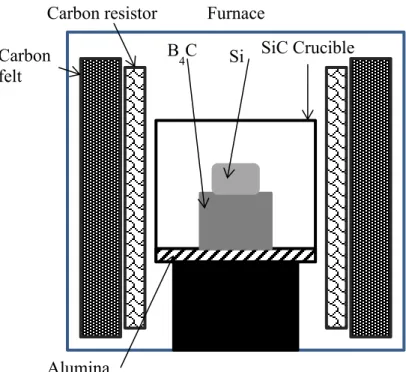
Figure III)4: Scheme of the first crucible page 63
Figure III)5: Heterogeneous heating caused by the electric arc in the
micro-wave furnace page 63
Figure III)6: Electric arc between SiC and silicon lump with local overheating page 64 Figure III)7: Scheme of the second type crucible used page 64 Figure III)8: Scheme of the third type crucible used page 65
Figure III)9: Crucible disposition page 67
sample I (low magnification) page 68 Figure III)13: Scheme of the difference between complete and incomplete
infiltration page 68
Figure III)14: Microstructure (SEM image) of the composite II.
(Backscattered electron detector) page 69
Figure III)15: Microstructure (SEM image) of the composite II Inlens detector
(Secondary electron detector) page 69
Figure III)16: EDX analysis and SEM picture of the composite II page 70 Figure III)17: The changes of final composition with increasing of the initial
porosity page 73
Figure III)18: Microstructure comparison between multimodal samples
and monomodal samples obtained with similar conditions page 75 Figure III)19: Microstructure of samples treated at different temperatures
(no dwell time) page 77
Figure III)20: the evolution of the degree of transformation with the maximum
temperature increasing for each phase page 78
Figure III)21: Microstructure of isothermal samples with differing dwell times page 80 Figure III)22: Evolution of the degree of transformations with the dwell time page 81 Figure III)23: Influence of both initial porosity and temperature: experimental
design page 82
Figure III)24: Volume variation reported on the experimental graph page 83 Figure III)25: Low magnification SEM picture (Secondary electron detector)
of sample obtained from preform with about 40% porosity (non-pre-sintered) page 83 Figure III)26: Microwaves composite microstructure (SEM), porosity
samples. a) and b) secondary electron detector (topographic contrast),
c) to f) backscattered detector (chemical contrast) page 84 Figure III)27: Degree of transformation of each phase appearance or disappearance
page 86 Figure III)28: Composite hardness plotted on the experimental graph page 87 Figure III)29: Answer surface modeling by the experiment plan page 87 Figure III)30: Microstructure of a) monomode heated sample (40% Dth) and
b) multimode sample (40% Dth) page 89
Figure III)31: Sample sized for ballistic test page 90 Figure III)32: Degree of transformation in function of the maximum temperature: composites RBBC heated by conventional or microwaves techniques page 92 Figure III)33: Composites obtained by microwave heating at 1400°C:
Figure III)37: degree of transformation in function of the initial porosity
(error on the porosity ±3%) page 97
Figure III)38: Gas effect on the composite microstructure page 98 Figure III)39: TKD results gave with the orientation color page 99 Figure III)40: TEM microstructure of CVF sample page 101 Figure III)41: TEM microstructure of MW sample page 102
Figure III)42: TEM picture of SiC grains page 103
Figure III)43: Scheme of the silicon carbide precipitation page 104 Figure III)44: Hardness versus residual silicon and B12(B, C, Si)3 contents
in final RBBC composites page 105
Figure III)45: Influence of the residual silicon amount on the hardness page 106 Figure III)46: Influence of the residual silicon amount on the Young modulus page 106 Figure III)47: Influence of the residual silicon amount on the Poisson
coefficient page 107
Figure III)48: Influence of the residual silicon amount on the flexural strength page 107 Figure III)49: Influence of the residual silicon amount on the toughness page 107 Figure III)50: Crack path in a) microwave sample and b) in conventionally
made sample according to the bibliography page 108
Figure III)51: Resume graph of compared hardness in function of the initial
Table I)1: Physical properties of B4C page 6 Table I)2: Sintering conditions and properties of “SPS boron carbide” page 9 Table I)3: Infiltration conditions in function of the molten material page 15 Table I)4: Summary of the mechanical properties for boron carbide and
boron carbide/carbon preform page 18
Table I)5: Mechanical properties of RBBC obtained by conventional or
microwave heating page 30
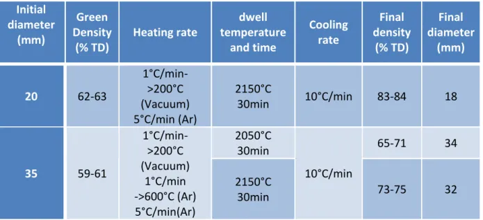
Table II)1: : pressing conditions and densities of green samples page 39 Table II)2: Sintering conditions of the preform and final densities page 39 Table II)3: Presentation of the samples used for different test page 40 Table II)4: Comparison Vickers hardness and Knoop hardness page 52 Table III)1:Abstract of the different working atmospheres tested page 61 Table III)2: preliminary study of the RBBC process under microwave page 66 Table III)3: Theoretical composition of composites from preforms with
different initial porosity page 73
Table III)4: XRD-couples with chemical etching results for multimodal and
monomodal composites page 74
Table III)5: Properties of monomodal pre-sintered samples and a multimodal
sample page 76
Table III)6: analysis of composites obtained at different temperature
(no dwell time) page 77
Table III)7: Properties of samples treated without dwell time page 78 Table III)8: Influence of dwell time on the composite composition (XRD page 81 Table III)9: Influence of dwell time on the composite properties page 81 Table III)10: Composite compositions for different initial porosity and
maximum temperature page 85
Table III)11: Mechanical properties for monomode 915MHz furnace sample
Since the first war, mankind has never stopped trying to find new ways of killing people and new ways of countering what they just developed. From leather armor to the latest Kevlar bullet proof armor, we seek to protect humans from the weapons they use. For protection purposes, material hardness is capital. Lightness must be kept in mind to maintain some agility and save fuel consumption for light vehicles and aircraft. During the last decades pure metal and their alloys were replaced by ceramics. Because ceramics are lighter and harder, they can be used as military and body armor. This replacement had been made possible because new materials or new ways of production tougher and less brittle technical ceramic were found. Boron carbide is a good candidate due to its very high hardness (36-42GPa). It is the third hardest industrial material nowadays known after diamond and cubic boron nitride. Another very interesting point is the very low density (2.52g/cm3) compared to the alumina (3.97g/cm3) actually used in military bulletproof jacket. Boron carbide is resistant to corrosion and neutron embrittlement and might be used in nuclear industry as control bar in nuclear reactors.
Nevertheless, there are some disadvantages, boron carbide is very stable, and so to obtain sufficiently density for optimal properties, sintering under pressure (30-40MPa), and temperatures above to 2200°C have to be used. These costly production steps decrease the economic potential of this material. Consequently, new production methods are being intensively investigated such as spark plasma sintering or reaction bonding to bring down the cost.
In the present work, we will focus on the reaction bonding, consisting in a composite fabrication by the chemical reactions between melted silicon and boron carbide or carbon. This technique decreases the maximum needed temperature from 2200°C to 1500°C (silicon fusion temperature) and even better, doesn’t need external pressure. The final material is composed of silicon carbide, residual silicon, residual boron carbide and new phase B12(B,C,Si)3 (named B12 hereafter). The obtained composite has a high cohesive strength (cracks are almost not deflected by the phases interface), elevated hardness, and high efficiency for ballistic impact test while maintaining a relatively low density. The major problem for high mechanical properties is the residual silicon which is fragile. The residual silicon can be reduced by controlling initial porosity. Many techniques are currently used to decrease the porosity as pre-sintering step (1900-2100°C), the use of multimodal powder mixture to increase green compact level, addition of elements to form stable silicide or to react with boron carbide to free more carbon and form more silicon carbide.
For the last couple of decades, reaction bonded boron carbide (RBBC) was intensively studied in conventional furnaces (i.e. resistive). In our case, we adapt such a method to microwave furnaces (2.45GHz and 915 MHz).
The advantage of this approach is the rapidity of the cycle, hence a considerable energy saving for the production of the composite: the boron carbide and silicon materials have a
materials involved are non-oxide, so heating cannot occur in air because both silicon and boron carbide would oxidize. In conventional furnaces they work under vacuum to avoid this problem but in a microwave oven, a vacuum can’t be used because it promotes plasma formation, which melts everything.
Therefore, our study will adapt the constraints related to the use of microwaves to the system B4C, Si, SiC.
The studies about solid-solid or sintering reactions have shown that the microstructures of the produced materials are generally finer than those obtained by conventional heating: the diffusion processes are favored, or even the diffusion mechanisms are modified. We will therefore investigate what the technique can best bring about improved system efficiency and achieved the final microstructures.
In addition, the link between microstructure and mechanical properties is sought. Results will be discussed in the light of the conventionally made composite properties. Finally, we will conclude on the specific role of the microwave heating on the Reaction Bonded Boron Carbide elaboration process.
The goal of this Ph.D. thesis is to study the effect of microwave heating on the fabrication parameters, microstructure and mechanical properties of reaction bonded boron composite. This thesis has also the purpose to compare both microstructures, physical and mechanical properties obtained after microwave method and conventional heating treatments. To do this study, a literature review was done in order to have an overview of the state of the art. This chapter compiles the data dealing with various aspects of the thesis subject:
- In the first part, the presentation of boron carbide is summarized including its physical properties and how to obtain pure boron carbide pieces. This will be useful for the preforms elaboration.
- The second part is devolved to the reaction bonding technique. It can be found general explanations on the reaction bonding methods and its particular application for boron carbide. The goal of this part is to understand the process of the infiltration of boron carbide by molten metals or alloys and the possible reactions. This part allows also knowing how the reaction bonding process is carried out in order to have a good work base for the thesis and select parameters: the powder, the initial porosity of the B4C preform, the Si form, the atmosphere and heating conditions. - In the third part, you can find explanations on the microwave heating.
In the last part, the link between microwave and different aspect of our work is presented. In particular, in terms of microwave sintering of boron carbide and reaction bonding carried out in a microwave furnace.
1 Boron Carbide
1-1 Structure and properties
Boron carbide is a solid solution which exists for the carbon content between 8.8 and 20 at% (Cf. figure I)1). The mechanical properties and lattice parameters change in this domain. In this thesis, we will concentrate on B4C which composition is the maximum limit of carbon.
Boron carbide lattice presents a rhombohedral structure (D3d5, R3m). The lattice is composed of 15 atoms, and the lattice parameters for the carbon rich limit are: a=5.607Å, c=12.095Å, V=329.30Å3 (Cf. figure I)2)[THE90].
Figure I)2: Boron carbide crystalline lattice [THE90] To produce boron carbide two reactions are possible:
- The boric acid reduction by carbon (two step reaction): 2 B2O3(l) +7 C(s) → B4C(s) + 6 CO(g) - The reaction of magnesium on boric acid and carbon:
2 B2O3(l) + 6 Mg(s) + C(s) → B4C(s) + 6 MgO(s)
Boron carbide, which is a refractory material, gets a high melting temperature (2490°C). Thus, it is one of the known hardest materials (42GPa), just behind diamond and cubic boron nitride. B4C presents an excellent abrasive power. It also has a low density (2.52 g/cm3), good cold and warm mechanical properties and, a high chemical resistance in severe environments. Nevertheless, it starts to oxidize at 600°C and is sensitive to hydrolysis. Another property is that boron carbide is a good neutron absorber.
All these characteristics make it a good choice in several domains like ballistic protection (hardness and lightness) or nuclear (neutron absorber). However, its low toughness and high hardness make it difficult to cut and constrains to use expensive diamond tools. So the machining is hazardous to the workpiece because it may fracture.
Properties (unit) Notation Value Density (g/cm3) ρ 2.52
Melting temperature (°C) MT 2450
Hardness (GPa) H 36-42
Young modulus (GPa) E 440-471
Shear modulus (GPa) G 186.5
Poisson coefficient υ 0.17
Flexural strength (MPa) Fs 300-480
Compressive strength (MPa) Cs 2855
Toughness (MPa.m1/2) K1C 3.2-3.6
Thermal conductivity (W.m-1.K-1) 28
Dilatation coefficient (K-1) Dc 4.5x10⁻⁶
Electrical resistivity (Ω.cm) 0.1-10
Maximum used temperature in air (°C) 540
Neutron absorption efficient section (Barns) 3850 (thermal neutron) 1-2 Boron carbide sintering
Pure non-oxide material densification without mechanical charge is very difficult. Pure dense boron carbide is very hard to obtain, because it has very strong covalent bonds, a low plasticity, a strong resistance to the grain boundary displacement (γb) and a weak solid state surface tension (γs). These properties are the exact opposite of those necessary for sintering. The oxidation of boron carbide at relatively low temperature (540°C) forms an oxide layer on the boron carbide particles, which limits further its densification. So the sintering of boron carbide is realized in an inert atmosphere (Argon). The advantage of the pressureless sintering is that it doesn’t need mold, so pieces with complex forms can be considered.
1-2-1 Pressureless sintering- effect of addition
For promoting the sintering of boron carbide, it could be added some additives. These sintering aids can have the following effects:
- Change the interfacial properties, by changing the particles surface energy (γs) and/or the grain boundary specific energy (γb). The elimination of absorbed species can lead to the increase of the γs. In contrast, the additions of species which segregate at grain boundaries allow frequently the decrease of γb. In the case of boron carbide, it is well known that the elimination of the oxide layer is favorable to the densification process.
- Accelerate the transport of the matter: the objective here is to accelerate the material transfert by reducing the path of the diffusing species. This can be attained by the increase of the contact number between particles and/or by the improvement of the
The sintering aids can be metals (Si, Fe, Mn, Al, Cu, Ni)[BOU85] which lead to a density close to the theoretical density (TD). But these additions can also lead to grain growth, and consequently to a decrease of mechanical properties. Another important point is that the impurity content can become too high for some applications (nuclear industry).
Some carbides, borides or oxides were studied too. As an example, for a thermal cycle between 2150 and 2280°C, the addition of 3 to 20 weight% of carbide allows obtaining a densification between 92 and 98.5% of TD. These additions decrease the bond strength. So carbides react completely with boron carbide to form boride and carbon as follows: B4C+MexCy→MexBy+C. The obtained carbon reduces the boron oxide on the boron carbide particles surface. Furthermore, boride and carbon well dispersed in the matrix ease the densification by delaying the grain growth. Typical carbides used are those of: Ti, Zr, Hf, V, Nb, Ta, Cr, W, Be [SCH96, RAD98, SIG98, ZAK90, PRO77]. These results are interesting but the obtained materials are composites B4C/MexBy due to the quantity of addition. Even if their mechanical properties are promising, the boron carbide grain size is relatively high (20µm).
Some oxides were also studied like stabilized zirconia [GOL01], or some borides like CrB2 [YAM03]. The obtained materials have high densification rates and an increase of the mechanical properties was observed.
The addition of carbon was studied [SCH 80, SCH 81, BOU 85, DOL 89, SIG 91] because it has a good effect on the boron carbide densification. It seems having two different effects: -First, reduction of the oxide layer on the boron carbide particles by the following reaction (1300°C): B2O3(l)+7C(s)→B4C(s)+6CO(g).
-Second, modification of the matter transport.
Some studies showed an interest for mixed additions, like carbon and silicon carbide. Indeed both achieve a specific role:
- Reduction of boron oxide by the carbon,
- Grain growth inhibition by the silicon carbide [BOU87].
This addition allows obtaining 92%dth after 15min at 2175°C in argon atmosphere.
All the previous studies were carried out in an argon atmosphere but some studies were also performed in a helium/hydrogen atmosphere [LEE02]. The hydrogen was used in pre-sintering step (1350°C) for removing the boron oxide layer by the reaction:
H2(g) + B2O3(l)→H2O(g)+B2O2(g). This method allows reaching a final density of 94.7% TD with a maximum temperature of 2230°C. The major drawback of this technique is the necessity to evacuate hydrogen before the sintering because H2 prevents the densification and reacts with boron carbide to form methane.
1-2-2 Pressure Sintering
The only way to obtain high densities without sintering additive is to carry out the sintering process under a charge. Some examples are described below: Hot Pressing, Hot Isostatic
Pure dense boron carbide material can be obtained by sintering under a uniaxial mechanical pressure (30-40MPa) and at a temperature between 2100-2200°C in an argon atmosphere [THE90]. This way of production is complex and very expensive. Moreover, the obtained pieces have simple geometric form. The carbon mold has to be covered by boron nitride to prevent the reaction between carbon and boron carbide. The morphology and the size of the initial powder are important for the density and the microstructure of the sintered material. A higher density is obtained for monomodal initial powder. Higher sintering temperature carried out on irregular growth grain, twins formation. Pressure sintering can be summary by three successive reactions. First, particles reorganization, while the closed porosity is still low and constant. Second, a plastic deformation leads to a close of the open porosity. Third, decrease of the closed porosity due to the volume diffusion.
1-2-2-2 Hot Isostatic Pressing (HIP)
Sintering step is realized without pressure in order to obtain pieces in which the porosity is closed; then a post-densification is realized by hot isostatic pressing. This method allows obtaining almost dense materials (>99% of theoretical density (TD)) with a 2000°C-200MPa-2h thermal cycle with an addition of carbon (1-3 weight %). [TAR04t]
1-2-2-3 Spark Plasma Sintering (SPS)
SPS is a method allowing a very quick heating rate. The piece to be sintered is placed in a carbon die (electrical conductor). Then, a pressure is applied on the die to maintain a contact between the carbon and the piece. Heating is provided by Joule effect: a pulsed DC current is applied at the end of the die causing heating of both the die and the piece if the latter is electrically conductive. In the case of non-conductive material only the die is heated, heating is transmitted to the sample by both conduction and radiation. Applied currents are very high so the system heats quickly (≈100°C/min). Moreover, non-thermal effects seem to appear because higher densities are obtained at lower temperature than that obtained in conventional sintering. This effect isn’t clearly identified yet, but some theories attempt to explain it. A local heating, on the current trajectory, which leads to very high temperature, or an electromagnetic effect that changes species diffusivity or even modifies the diffusion, and promotes the densification.
In the case of boron carbide, SPS can be used to obtain dense piece at lower temperature than in conventional furnace (1600-2200°C), and high pressure (75-80MPa) have to be used to reach highest densities. Many studies were carried out to define the optimal sintering parameters (table I)2). George, in his PhD [GEO16t], reach a final density >95% after 5min at 1750°C with a charge of 75MPa. He shows that the charge effect reaches a maximum between 50 and 75MPa (86% TD to 97% TD respectively) but higher charge doesn’t change the finale density.
Table I)2: Sintering conditions and properties of “SPS boron carbide”.
Materials
B4C
[VAS16, SAI14, HAY10a, LI14, BAD14, MOS13, MOS14, MOS15,
NIU16, HAL15,GEO16t] B4C/Al2O3 [SUN14] B4C/Si [REH15] B4C/SiC [SAH12] Atmosphere Vacuum N2 [VAS16, BAD14] Ar [VAS16, BAD14] Vacuum Temperature (°C) 1100-2200 1800-1850 1700-1800 1700 1700-1750 Pressure (MPa) 32-75 30-100 60 40 Density (%) 65-100 95-98 98 72.8-98.8 99.4-99.8 88.3-98.8 Hardness (GPa) 0.2-37.6 24.8-42.5 22.5-38 79-90 34-36 31-35.3 Toughness (MPa.m½) 2.6-4.6 3.2-4.5 2.2-6.1 Young Modulus (GPa) 19-570 Flexural strength 25°C (MPa) 316-828 300-575 [VAS16] 400-510 [VAS16] 600-620 Flexural strength 1600°C (MPa) 460-650 [VAS16] 590 [VAS16] 1-2-3 Conclusion
The densification of boron carbide is possible but the methods imply high temperature, high pressure or sintering additives. The high temperature and high pressure furnaces remain very expensive and the additives change the mechanical properties, and the needed impurities contents can become too high for using it. But the characteristics of boron carbide
leads to composite but mechanical properties are sufficient for some application. This technique will be explained in the next part.
2 Reaction Bonding Boron Carbide (RBBC)
In the previous part, the properties and direct sintering of boron carbide were presented. Even if using pure boron carbide bodies is currently difficult, some methods allow using rich boron carbide pieces. In this thesis, we will concentrate on one of them: the reaction bonding.
2-1 General principle
The reaction bonding belongs to the reaction forming process family. In this method, the pieces’ consolidation involves chemical reactions creating links between particles and filling the porosity, instead of neck-growth mechanism. Consequently, the piece shrinkage is almost null. It is not necessary to do post process machining, because the final form of the workpiece can be used for the reaction. The infiltration step occurs at temperature lower than the sintering temperature and it is a pressureless method, so the production cost is decreased. This method consists in the infiltration of molten metals or alloy which will react with the infiltrated ceramic porous body and/or atmosphere to form new phases. This reaction will create a chemical bond between the initial ceramic body and the infiltrating material after cooling. In the majority of cases, the infiltrated material is a ceramic material, because of the difficulties to obtain dense pieces and, the infiltrating material is a metal or alloy. This technique is already used for SiC and is named Reaction Bonded Silicon Carbide (RBSC). We describe here the RBBC: Reaction Bonded Boron Carbide, which is the subject of our work.
2-2 Reaction Bonded Boron Carbide formation
A porous preform of B4C ceramic is infiltrated by molten metal or alloys (generally the silicon) (Cf. figure I)3). The ceramic and molten metal reacts with each other to obtain new phases (SiC and B12(B,C,Si)3) and leads to a consolidation of the piece. The major advantage of this method is the temperature of heat treatment that is the melting temperature of the metal or alloy used for infiltration. This is a pressure free method too, of these two points results a decreasing of the production cost.
According to the bibliography, silicon carbide is formed in RBBC from silicon and from several possible sources of carbon.
The “Reaction bonding” technique is a solid/liquid interaction method, so some parameters are important to control:
- initial porosity amount, that conditions the surface reaction (Cf. chap. I 2-3)); - porosity size, that plays a role on the matter repartition in the piece;
- preform composition and infiltrated material composition, that could change the reaction during the infiltration step (Cf. chap. I 2-3);
- atmosphere, that could change the wettability of the liquid on the substrate (Cf. chap. I 2-4);
The reactivity is explained in paragraph 2-5.
Figure I)3: Scheme of the reaction bonding
2-3 Preforms elaboration:
In the literature, it can be possible to distinguish two main families of preforms: the first one with only pure boron carbide [WAN14, TAR04, HAY09a, FRA03, CAF12, WU12, HAY10b, HAY10c, HAY10d, HAY09b, CAF14, ALM14, HAY09, KOU02, HAY08] and the other one with additions of carbon or silicon carbide [HAY06, THU13, WAN14, HAY10c, WU12, HAY10d, ZHA14a, BAR13, ZHA14b]. Except for three articles [THU13, TAR04, ALM14], the preforms are uniaxial pressed at a pressure between 10-200MPa. In the article [THU13], preforms were uniaxial pressed at 922MPa. Tariolle et al. [TAR04] used first a uniaxial compaction at 60MPa, followed by an isostatic compaction at 350MPa. The pressed samples are generally sintered in order to decrease the initial porosity: for pure boron carbide, the sintering steps were carried out at a temperature between 1900-2200°C; for the mixed powders, preforms were heated at 900°C for 5h [WAN14] or at 1550°C for 3h [WU12] (the initial porosity is not mentioned).
The addition of carbon can be realized in initial powder mixture [THU13, WAN14, WU12, ZHA14a, ZHAb] with carbon powder, or a mixture of carbon and paraffin, or resin. It could also take place after pressing or sintering by infiltration of 50/50 sugar solution [HAY10a,
B4C (+ C) +porosity Si
B4C + SiC + B12(C,B, Si)3
Infiltration of Si +reaction
of the preforms tested by the authors goes approximately from 15 to 40%. Different parameters of elaboration have to be studied:
- The initial powders: it is certain that the size of the initial powders will play a role on the microstructure of the preform. The fine powders lead to fine pores and in small quantity. Articles [DAR12, HAY08] treat of powder mixtures with various grain sizes (130,70,50,13,1µm): that facilitates the grain arrangement during pressing, and allows obtaining homogeneous samples, whose size and quantity of pores can be controlled. Despite the resulted composite is heterogeneous (large grains cohabiting with small ones), this way appears very interesting.
- Compaction: if the compaction pressure is too high, some cracks could appear in the preform after the sintering step. [DAR12]
- Debinding step: when binder or dispersant are used for compaction or mixing the powder they have to be removed in a debinding step to prevent the preform from cracks during sintering. [TAR04]
- The sintering step: direct cold compacted samples or sintered samples can be used for infiltration. [DAR12, TAR04, FRA08]
- The presence or the absence of free carbon has no influence on the final composition but the shape of SiC formed during the infiltration process depends on the carbon source. Best mechanical properties are obtained when no free carbon is added in the preform. In some cases, Si can be added in the preform. [HAY10b]
For all previous points, we decided to focus on preforms obtained with one type of powder (composition and size) compacted at 100MPa with sintering step at a temperature between 2000°C and 2200°C. Some additional samples were obtained with powder mixtures (SiC+B4C and B4C with different grain sizes).
2-4 Infiltration process 2-4-1 Wettability
2-4-1-1 Generality on wetting
Wettability [Larousse dictionary] is a property which characterizes the behavior of the surface of a material in the presence of a liquid. Wettability is defined by the contact angle (θ); this angle depends on the substrate, the liquid, the temperature, and the atmosphere (Cf. figure I)4). The Young-Dupré equation ties the contact angle and the three surfaces tension:
𝛾𝑙𝑣𝑐𝑜𝑠𝜃 = 𝛾𝑠𝑣− 𝛾𝑠𝑙 Equ.1
With: - γlv the liquid vapor surface tension on the free liquid surface, - γsv the solid vapor surface tension on the free solid surface,
- γsl the solid liquid surface tension on surface between solid and liquid, There are two types of system (substrate/liquid):
- Wetting system: partially wet for θ<90° and completely wet θ=0°. Liquid can spread on the substrate surface. Smaller θ is, more liquid will spread on the substrate.
- Non-Wetting system: 180°>θ>90°. Liquid tends to form a drop on the substrate surface. Higher θ is, more liquid will have a prefect drop form. Contact angle cannot be higher than 180°.
Figure I)4: Contact angle
A good wettability, smaller θ angle is mandatory in order to infiltrate the preform without any applied pressure. The wettability study can also give an idea of how the Si/B4C interface evolved. Indeed, wettability in reaction bonded system is not simple because there are other types of wetting which play an important role.
2-4-1-2 Reactive wetting
In this case, substrate and liquid can react. Three possibilities are expected: substrate dissolves in the liquid, new phases appear at the interface between liquid and substrate or it could happen both.
2-4-1-2a Substrate dissolution
This type of wetting depends on the solubility of the substrate (S) in the liquid. If S solubility is limited, the interface can be considered flat but the surface tensions are modified.
If S solubility is not limited, the interface geometry changes, a hole appear below the liquid drop. In this case, the contact angle change followed the figure I)5
A new solid appears at the interface between the substrate and the liquid. The liquid is now in contact with the new phase. The contact angle of this new solid has to be considered. This can change the wettability; a non-wetting system can become a wetting one, for example.
2-4-1-3 Bibliography about wetting
In their Ph.D., Michael Aizenshtein and Rana Israel [AIZ05t,ISR09t] showed the importance of the porosity size for a good infiltration. When the contact angle is lower than a critical value (50° to 85° as a fonction of the porosity shape) the infiltration is spontaneous. That is the case of molten silicon. If the pore size is too small, infiltration may be difficult. It is then possible to close the porosity before a complete infiltration. In this case, non-infiltrated regions may be present in the samples, which make the piece fragile.
All the collected data show a good wettability of B4C by molten silicon. This wettability allows the infiltration of silicon without external pressure. Moreover the wettability of reaction products (SiC, B12(B,C,Si)3) is good too so their formation don’t be harmful for the infiltration. The influence of micro-waves on the wettability is not known, but we think a priori that it will not play a major role on the process. So no quantitative wettability studies were carried out in this thesis. The wettability of boron carbide by alloys (Cu-Si, Cu-B, 2519Al, Fe-B, Fe-C, Fe-B-C) was studied by many authors [FRO03, FRA04, AIZ08, WU14]. All studies showed a good wettability (<90°) when silicon or boron were added in these alloys. In many cases, a reactive wetting occurred with the formation of a layer between boron carbide substrate and wetting material.
Boron nitride substrates are no wetted by pure silicon, contact angle between 105° and 145°C. Boron nitride can be used as barrier to provide silicon spreading. We will use this product to protect the crucible.
2-4-2 Infiltration condition
In most cases [HAY06, WAN14, HAY10a, HAY09a, HAY10b, HAY09b, HAY10c, HAY09c, ZHA14a, ZHA14b, BAR13, HAY08], boron carbide preforms were infiltrated by silicon with a minimum purity of 98.4%. Others ones treat of the infiltration of silicon alloys with Cu, Al, Mg or of other metal (Al, Mg) or alloy (AZ91). The infiltration condition depends on the infiltrating materials: for Si the infiltration temperatures were between 1450 and 1600°C; lower temperatures were needed for alloys containing Cu (750-1100°C) and Mg (850-1000°C) due to eutectic compositions (53% atomic of Si for Mg alloys). Pure Cu didn’t infiltrate boron carbide preform.
The atmospheric conditions are also influenced by the infiltrating material: for pure Si and Mg-Si alloy, the infiltration step was carried out under vacuum (1Pa≈10-5 mbar). Infiltration of Mg alloys was carried out under partial vacuum with a 6.6KPa of Mg vapor. Cu alloys were infiltrated under argon atmosphere. Table I)3 summarizes infiltration conditions mentioned in the bibliography.
Table I)3: Infiltration conditions in function of the molten material.
2-5 Reactivity
The reactivity between silicon and boron carbide was studied by some authors [TEL90, HAY09c]. They found that the reaction can be summarized:
- As soon as the temperature reached 1000°C, B4C can release C and incorporate Si in its structure, forming a solid solution named B12(B,C,Si)3
- At a temperature above 1100°C, the carbon in the B4C powder can also react with the silicon to form β-SiC. This carbon can be in the initial B4C powder (impurity or addition). It is also possible to make carbon additions in the preform, as described below.
Since 1380°C a ternary liquid is formed that promotes the formation of the B12(B,C,Si)3 phase. Between 1380°C and 1410°C, the SiC concentration is multiplied by five. At 1500°C the formation of B12(B,C,Si)3 is total after an annealing of 1h. To summary:
T≥1000°C : B4C+Si→B12(B,C,Si)3+C T≥1100°C : C+Si→β-SiC
T≥1380°C B,C,Si (L)→↗ B12(B,C,Si)3 1380°C≤T≤1410°C : ↑SiC
According to Werheit et al. [WER94] and Tell [TEL90], the maximal solubility of silicon in boron carbide phase at 2323K (2050°C) is about 2.5at%. Hayun [HAY09t] used Thermo-Calc software, a model developed by Kasper [KAS96t] and extrapolation of the thermodynamic
Melted materials Atmosphere Temperature range (°C) Si [HAY06,WAN14,HAY10a,HAY09a,HAY10b, HAY09b,HAY10c,HAY09c,ZHA14,BAR13,HA Y08, ZHA14b] Vacuum (1Pa≈10-5 mbar) 1450-1650 Cu-Si alloys [TAR04] Argon 750-1100 Mg-Si alloys [CAF14] Vacuum (1Pa≈10-5 mbar) 850-1000 Al-Si alloys [FRA03,WU12,ALM14] Vacuum (10-2 Pa) 1200-1400 Mg alloys (AZ91) [CAF12,CAF14] Partial vacuum (6.6Kpa) 850 Al and Al alloys
Figure I)6: Isothermal section of the B-C-Si phase diagram at1753K (calculated by Hayun[HAY09t]).
Here is cited the discussion in Hayun thesis:
“The point A in figure 7 symbolizes the system before any interaction but after the fully
infiltration. The calculation was made for 40% of porosity sample so the atomic composition is 63 at% B, 16 at% C and 21 at% Si. The dashed lines connect the Si corner (initial phases)
and boron carbide (B4C) region (initial phases). According to the model the equilibrium point
of the system at 1753K is composed by SiC, B12(B,C,Si)3 and liquid. If the equilibrium was
reached during the reaction so no more boron carbide remains after the reaction. According
to the bibliography there are almost always remaining boron carbide, Hayun explains this by
the precipitation of the newly formed B12 phase at the surface of boron carbide grain, called rim region. This layer acts like a diffusion barrier and prevent the total dissolution of the initial boron carbide particles. According to the bibliography the formation of the rim region
is due to a dissolution-precipitation process [TEL90, TEL87, GUG72]. This type of core-rim
structure is very often observed in composite when liquid and solid phase react to form the final composite structure. The presence of rim-core structure is observed in metal/ceramic
system when ceramic is partially soluble in the liquid metal [CHE01, AND01, MOS66] and in
some metal/tungsten based composite after liquid phase sintering. The formation of the core-rim structure in a solid/liquid system is attributed to the partly dissolution of original
particles (B4C) in the liquid (molten Si) and precipitation of a new solid phase (B12(B,C,Si)3) at
the surface of the initial particles.
The formation of a layered rim region was discussed by Chen et al.[CHEN01]. The authors
suggested that the inner layer is formed as a result of the precipitation of a new phase under quasi-isothermal conditions, as long as the original ceramic phase is in contact with the liquid. The outer layer is formed during cooling when solubility of components changes. The layer resulted from congruent or stoichiometric dissolution in the liquid and its precipitation as a new phase (with new composition) determined by this new equilibrium.
If the original particles didn’t dissolve in the liquid a solid state diffusion is possible the rim region growth until since the diffusion through it is too slow to continue significant growing. Boron carbide is a strong covalently bond material so its components diffuse slowly, one of the reasons it is extremely difficult to sinter, so it dissolves without any compositional changes (congruently). It dissolution in the melt conduct to the concentration of boron and
carbon of: 1mole of B4C give 4 mole of dissolved boron and 1 mole of dissolved carbon”.
Hayun calculated the concentration equilibrium for the system presented before and it obtained a concentration of 8 at% of boron. He found that the maximum possible content of boron in the liquid at this temperature is 6.6 at% for higher amount the precipitation of B12 phase occurs. This phase precipitates at the initial boron carbide interfaces; this causes the apparition of the core (B4C)-rim (B12) structure. He also calculated the possible composition of the B12 phase: B12C1.99Si0.037.
According to bibliography it still remains unreacted silicon in the final composite. 2-6 Microstructure-properties relationships
The Table I)4 shows the properties of composites produced by different authors with different infiltration conditions (regrouped by melted material). This shows that best mechanical properties are obtained by infiltration of “pure” silicon in boron carbide preforms. The mechanical behavior of the final composite depends on the initial preform features in terms of porosity, composition and grain size, the melted material (Cf. table I)4), the thermal cycle (dwell time, maximum temperature).
Composites infiltrated with aluminum:
In the case of composites infiltrated with Al or Al alloy, it is possible to change the mechanical properties of the composite by post infiltration heat treatment (quenching…). Therefore, after the infiltration, it is possible to shape the piece then to make an annealing to obtain better mechanical properties.
For Al-Si samples with 40% of initial porosity the hardness increased from 4,6GPa to 12.2GPa before and after a post thermal treatment respectively. In the same time, the hardness of the samples with 18% of initial porosity is stable before and after thermal treatment ≈25GPa.
Before post thermal treatment the boron carbide size plays an important role; indeed the flexural strength increases from 370±25 to 543±22 MPa when boron carbide size grows up from less than 10µm to 22-59µm. After post heat treatment, this effect is lower (622±90 MPa to 678±69 MPa).
However, the mechanical properties are lower than those obtained by silicon infiltration. Consequently, they could not be used for ballistic application.
carbide/carbon preform Melted material Initial porosity % Young’s modulus (GPa) Flexural Strength (MPa) Vickers Hardness (GPa) Toughness (MPa.m1/2) Si [HAY06,WAN14,HAY10a,HAY 09a,HAY10b,HAY09b,HAY10c, HAY09c,ZHA14a,BAR13,HAY0 8, ZHA14b] 20-44 300-430 210-410 16-25 3.3-4 Cu-Si [TAR04] 13-30 21±4 Mg [CAF12] 269±4 341±16 8.7±1 Mg90.8%-Al8.25%-Zn0.63%-Mn0.22%-Si0.035% (AZ91) [CAF12,CAF14] 295±3 327±19 11.7±2
Al (before heat treatment) [TUN11]
43-48
370-543
Al (after heat treatment)
[TUN11] 662-678
Al (with 2min of dwell time)
[KOU02] 166-183
111-201 (tensile
test)
Al (with 15min of dwell time) [KOU02]
165-194 136-229 (tensile
test)
Al-Si (before heat treatment) [WU12,ALM14,FRA03]
16-50
216-299 201-328 4.6-25 4-5.1
Al-Si (after heat treatment)
[FRA03] 12.2-25.5
Si-Mg [CAF14] 20 356 230±22 17±3
RBBC obtained by silicon infiltration:
The hardness of the composite infiltrated with silicon changes with the residual silicon content, it increases from 16 to 25 GPa when the residual silicon decreases from 30 to 8 vol%. The same effect was observed for Young modulus which increases from 330 to 430 MPa.
The residual silicon weakens the composite and it has to be pointed out that all authors found residual silicon after infiltration whatever the conditions.
Flexural strength seems to be independent of the residual amount of silicon but it strongly depends on the elaboration conditions of the preform: sintered (400±10MPa), monomodal powder (275MPa), multimodal powder (325MPa) or carbon added (250±25MPa).
hardness: when particle size increases from 18.65 to 63.35µm, the hardness increases from 1261 to 1674kgf/mm2. This is due to the number of interface boundary. Indeed, these interfaces are weaker than boron carbide particles. There are more interfaces in the imprint when initial boron carbide grain size is smaller. The effect is inverted for fracture toughness and flexural strength when particles size increases these properties respectively decrease from 5.76 to 3.4 MPa.m½ and from 403 to 256 MPa.
The other team [HAY09a] worked on the multimodal powder to obtain a preform with a low porosity without pre-sintering step. They obtained 25% of initial porosity using multimodal (different proportion of each size) boron carbide powder instead of 40% of initial porosity for monomodal powder. The composites were composed of four phases, residual boron carbide, residual silicon, newly formed silicon carbide and newly formed B12 phase. The mechanical properties were the same than that of monomodal powder samples initially pre-sintered up to 25% porosity.
Hayun et al. [HAY10b], studied the influence of the carbon source. There are two major carbon sources: carbon additions and boron carbide itself. The toughness is from 2.5 MPa.m½ to 3.6 MPa.m½ and flexural strength from 250MPa to 400MPa when only boron carbide is used in the preform. The carbon addition has no notable effect on the hardness and Young modulus, but it lowers the toughness and flexural strength. It is noteworthy that the carbon source has no effect on the composite composition but it changes the microstructure (Cf. figure I)7).
Figure I)7: SEM (secondary electron) micrograph of composites after infiltration a) without free carbon and b) free carbon addition [HAY10b]
As it can be seen on figure I)7 the final morphology of SiC is strongly influenced by the carbon source, boron carbide for Figure I)7a and carbon added for figure I)7b. The plate-like silicon carbide obtained in the case of no carbon addition is favorable to the material strengthening.
addition of SiC added in the initial powder lead to: - An increase in toughness from 4.5 to 4.9 MPa.m½, - A decrease in hardness from 3150 to 2800 Hv, - A decrease in flexural strength from 320 to 240 MPa,
The effect of the temperature was also studied [ZHA14a] in the case of B4C-Si system. Authors measured the evolution of the hardness, flexural strength and toughness for the same initial state samples. For hardness (15 to 18.5 GPa) and flexural strength (310 to 340MPa), in first time the increase of maximum temperature was profitable, in the range 1450 to 1600°C. But when temperature reached 1650°C, both measured parameters fell down, respectively 13GPa and 290 MPa. Toughness increased when temperature increased (3.3 to 4MPa.m½).
Figure I)8: SEM (secondary electron) micrograph of composite after infiltration [HAY10c] Figure I)8 shows a typical microstructure of a sample after infiltration without carbon addition, it was composed of boron carbide (5µm) compacted. Newly formed silicon carbide (white needles) can be easily observed, the black particles were boron rich phase identified by Frage et al. as solid solution of B12(B,C,Si)3, and the grey area was identified as residual silicon.
Hayun [HAY10b] measured the nanohardness of the B4C (42±3.3) and the B12(B,C,Si)3 (46.1±4.2) and the Young modulus of B4C (460±23) and the B12(B,C,Si)3 (474±34).
The transformation of B4C to B12(B,C,Si)3 seems interesting for the mechanical properties. In his thesis [HAY09t] Hayun studied the mechanism involved in the B12(B,C,Si)3 formation. As mentioned before, B12 appears in a core-rim structure with the initial boron carbide particles. This structure is due to a dissolution/precipitation mechanism.
He also observed a highly dependence between the carbon source (free carbon or boron carbide) and the SiC morphology. TEM analysis showed that “β-SiC always precipitate from
silicon melt as single plate-like particles with the {111}β habit plane.” He also observed an
boron carbide layer, in direct contact with silicon; the dissolved boron carbide goes inside the preform by the silicon flow. Indeed, he observed that upper boron carbide limit is displaced to the composite core from about 150µm (Cf. figure I)9).
Figure I)9: [HAY09t] Top layer of the infiltrated composite
He also observed a strong interaction between the core (residual boron carbide) and rim (the newly formed B12(B,C,Si)3). Indeed, cracks go through the interphase without being deflect. He compared a no-pre-sintered preform and a pre-sintered one and surprisingly there were almost no mechanical properties differences. This lack of differences is attributed to the microstructure and composition similarities. In the case of pre-sintered materials, the necks formed during the sintering step are preferentially attacked by molten silicon and transformed in B12 that acts as a link between the residual boron carbide particles. Such a link appears also for no-pre-sintered preform with the dissolution-precipitation mechanism. Indeed, B12 precipitates at the boron carbide surface and could link particles. In both cases, a continuous boron carbide/B12 skeleton is obtained.
In all cases, a strong link between the amount of residual silicon and the mechanical properties was observed: less residual silicon causes an increase of the mechanical properties.
We focus our work on the use of silicon to elaborate RBBC composites. The process:
- The way of preparation of the infiltrate metal or alloy modifies the behavior during infiltration step and final composition of the composite. The silicon can be in the form of powder, lump or pellet. It can be very pure (99.999%), or less (down to 98.4%).
- The atmosphere: vacuum is usually used, from 5.10-4 to 10-5 mbar.
- Thermal cycle: the usual temperature range is 1450-1500°C, with a dwell of 10-30 min, but higher temperatures (e.g.: 1650°C) or dwell time (up to 4h) are found in the literature.
The microstructures:
- The reaction bonding is possible, and SiC is obtained. Often, an intermediate phase B12(B,C,Si)3) is formed between B4C and SiC.Residual silicon is often present, that can be removed by chemical treatments. B4C can be totally transformed into B12(B,C,Si)3 phase if grains are fine in the preform.
- The form of the silicon carbide depends on the presence of carbon in the preform: if this latter is present, polygonal SiC platelets are formed. If no free carbon is present in the preform, SiC grains are platelets.
The mechanical properties:
- The infiltration temperature and the time passed at high temperature influence the final composition and the mechanical properties. For pure Si infiltration, the best temperature would be 1600°C.
- The intermediate phase B12(B,C,Si)3 does not affect the mechanical properties. High values for mechanical properties can be obtained: e.g. Hardness 2300±250 HV, Young modulus 400±10GPa, Flexural strength 318±20 MPa.
- The fact that the preform is sintered does not affect the final mechanical properties.
3 Microwaves Heating
3-1 Microwave heating principle
Microwave is a field of electromagnetic waves (EW) from 300MHz to 300GHz which correspond to wavelength between 1 m and 1 mm. The conventional frequencies used are:
915MHz, 2.45GHz, 5.8GHz and 24.125GHz. An EW plane wave is defined by two
perpendicular vectors:
- Electric field vector E, -Magnetic field vector H,
In an infinite environment without dielectric loss, the two vectors are in phase.
The wavelength (λ) is related to frequency (f) and light vacuum speed (C), and is defined by the following equation:
𝜆 =𝐶
The EW radiance for the microwave can be produced by several sources:
- Magnetrons are the most common wave’s sources. They work at a frequency between 1 and 30 GHz.
- Klystrons are used for high powered radiance source (can reach several hundred kW) in the frequency field between 0,3 and 100 GHz.
Gyrotrons allow obtaining radiance in the frequency field between 30 and 300 GHz and a maximum power of 1MW.
Microwave cavity is the limited metallic space where the sample is put; it can be single-mode or multisingle-mode.
-Multimode one is a cavity with higher size than that of the waveguide (which “transports” waves from microwave generator to cavity). In the cavity waves undergo multiple reflections. Those reflections lead to a constant distribution of the electromagnetic field, but this latter is heterogeneous. To homogenize the heating, a mixing paddle or a turntable can be used.
The mixing paddle is a metallic turning propeller which disturbs the electromagnetic field. This perturbation leads to an average distribution of the electromagnetic field. The turntable is used in home microwave, the electromagnetic field distribution is constant and heterogeneous but the sample moves inside this field where it receives an average energy.
-Single-mode cavity have particular sizes, it is adjusted by short-circuit. This allows creating a resonance phenomenon. Consequently, the sample can be put in a belly or in a node of the magnetic or electric field, which allows a finer controlled of the process. The size of samples is limited with this type of cavity.
The behavior of material with respect to EW (reflection, absorption or passage through) depends on dielectric properties of the material.
The conductor materials are generally blackout (full reflection).
The dielectric materials present different behaviors related to their complex permeability *.
∗= ′− 𝑖′′ Equ.3
In equation 3, the real part ’ is known as dielectric constant. The imaginary part ’’ is known as loss factor, and determines how the materials absorb the electromagnetic field. Materials with high ’’ highly absorb electric energy and so they heat quickly. On the opposite low ’’ materials are characterized by a low absorption, so there are transparent or partially transparent. Dielectric properties can change with the temperature, that’s why even fully transparent material when they are heated above a critical temperature start to absorb micro-wave.
𝑡𝑎𝑛=’′
’ Equ.4
The loss tangent characterizes the material and is used as indicator to describe how it dissipates microwave energy during the heating stage.
For all materials, the dielectric properties change with frequency.
For ceramics, microwave heating is due to the polarization; the electron mobility causes the energy dissipation and leads to the heating of the material. It exists different types of polarization:
-Electronic polarization: due to the displacement of the electronic cloud under electric field. This displacement creates a misalignment of the positive charge (core) and negative charge.
-Ionic polarization: due to the displacement of atoms or groups with opposite charge in equilibria position under an applied electric field. The asymmetric charge distribution between non identic atoms is a permanent dipolar moment source. If an external electric field is applied, they orient themselves in the direction of this field (orientation polarization).
-Space charge polarization: due to the blocking of the charge displacement by a physical barrier (grain boundary)
The microwave penetration depth named dp in materials is the depth where the transmitted power fall at 0.368 (1/e with e the Euler number) of its surface value. It is calculated with the following equation.
𝑑𝑝 = √ 1
𝑓𝜋µ𝜎 Equ.5
With: µ: permeability (N/A2)
f: the frequency of the considered wave in Hz σ: electrical conductivity (S/m)
According to the equation (5) the microwave penetration depth for a given material is a function of the wave frequency. The ratio of the penetration depth for 915MHz and 2.45GHz is the ratio of their frequency, i.e. dp915= 1.64xdp2.45. As it can be seen, a lower frequency is better for penetration depth, so for the heating homogeneity.
3-2 Three heating methods
Heating with microwave can be purchased by three ways: direct way, indirect way and hybrid.
3-2-1 Direct way
This way of heating is the one use in domestic microwaves furnaces to heat water. Samples are heated directly by the microwaves. This way of heating is characterized by a volume heating, the core of the sample is hotter than its surface. It is used when samples absorb microwaves since the room temperature. Figure I)10 shows a simplified (the influence of depth penetration is not taken into account) scheme of direct heating.
Figure I)10: Volume heating scheme 3-2-2 Indirect way
When a material does not couple with microwave, a susceptor part may be used to indirectly heat the sample. If a sufficient mass of susceptor surrounds sample, the microwave field could not attain the sample; on this way, one can heat metallic material. This way of heating is characterized by a surface heating, the surface of the sample is hotter than its core. This type of heating looks like at this one we can find in conventional furnace. Figure I)11 shows a simplified (homogenous heating) scheme of indirect heating.
Heating direction
Sample
Heating direction
Sample Susceptor
3-2-3 Hybrid
When a material couples at high temperature but not at room temperature or if its weight is not enough to heat up, we can use a susceptor to help. Microwave has to reach sample. However, the susceptor must not be too heavy or surrounds the sample. This way of heating is characterized by a mix between a surface heating and a volume heating. Figure I)12 shows a simplified (same temperature for samples and susceptor) scheme of hybrid heating.
Figure I)12: Surface + Volume heating scheme = hybrid 3-3 Microwave cavity
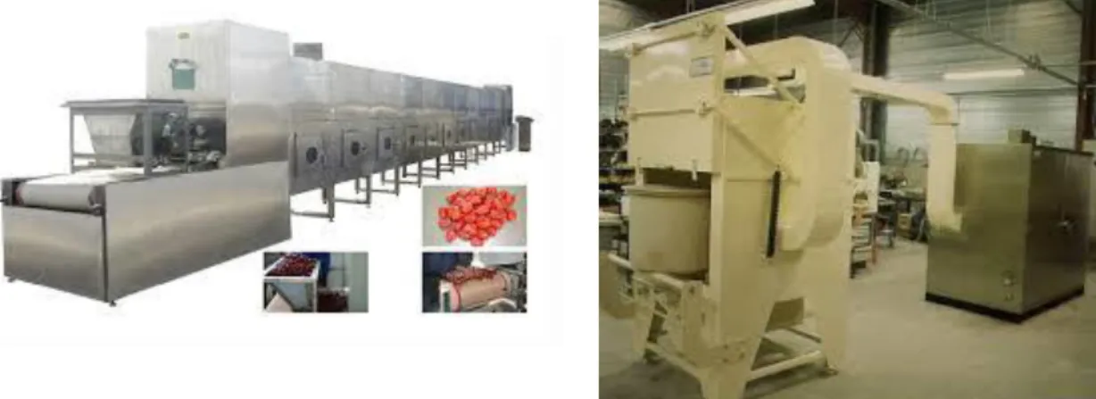
There are different sizes of cavity from domestic microwave to bigger industrial ones (Cf. figure I)13). Currently industrial microwaves are principally used in food field or other low temperature applications.
Figure I)13: Industrial microwave furnaces
Single-mode cavity
A single-mode cavity has a particular design: a parallelepipedic tube whose cross-section is that of the waveguide. Its sizes are directly correlated to the frequency used for heating.
Heating direction
Sample Susceptor
To calculate the minimum size of a waveguide, we can use the following equation [INT1]:
𝜆𝑐 =𝐶
𝑓 = 2. 𝑎𝑐 Equ.6
With λc the wave length cut lower limit by the waveguide, C the light speed,
f the frequency of the cut wave,
ac the highest width of the waveguide section,
To allow the wave transportation with a waveguide, it has to be at least 30% higher than the ac value calculated from the equation 5.
The smallest section width has to be the exact half of the a value.
In this type of cavity, it is possible to select which field will heat the sample. It is possible to adjust the cavity in order to place the sample in magnetic mode or electric mode. Single-mode cavity is therefore useful to know what type of field, electric or magnetic, makes it possible to heat the sample. For a single-mode furnace, the heating is very efficient if the sample is placed in a maximum field (magnetic or electric) area. At the contrary, if sample is not located at the maximum field area, heating will almost do not take place.
Multimode furnace
For multimode furnaces (like domestic microwave furnaces), the waveguide dimensions are the same than for single-mode cavity for the same frequency. Just the cavity size changes, with fewer constraints for multimode than for single-mode, the cavity size can take different values; the only thing is to check that the cavity center is in a maximum of the field. This freedom on the size allows making bigger cavity for multimode furnace. But in this type of cavity, it is impossible to select which field is used for heating. Heating is also more difficult in multimode than in single-mode, because for the same power supplied by the generator, the field will be lower on the sample. Thus, in order to study finely the microwave-matter interaction, it is preferable to use a single-mode furnace.
As previously, lower frequencies are better for penetration depth and the cavity size is directly related to wave frequency (Eq.6). According to the equation 6, a single-mode cavity 2.45GHz has a section of at least 79.43*39.715mm² is needed and 915MHz single-mode cavity has a section of at least 163.5*81.75mm² (Cf. figure I)14). The same result is found again for multimode cavity. According to these two points, a lower frequency is better to sinter large pieces.
However, the dielectric properties of the material depend on the frequency. A material could couple very well at 2.45GHz but not well at 915MHz.
![Figure I)15: Typical SEM microstructure of RBBC heated with microwaves, and XRD analysis [THU 12]](https://thumb-eu.123doks.com/thumbv2/123doknet/8244473.277398/41.892.114.799.136.387/figure-typical-sem-microstructure-rbbc-heated-microwaves-analysis.webp)