HAL Id: hal-00586198
https://hal.archives-ouvertes.fr/hal-00586198
Submitted on 15 Apr 2011
HAL is a multi-disciplinary open access
archive for the deposit and dissemination of
sci-entific research documents, whether they are
pub-lished or not. The documents may come from
L’archive ouverte pluridisciplinaire HAL, est
destinée au dépôt et à la diffusion de documents
scientifiques de niveau recherche, publiés ou non,
émanant des établissements d’enseignement et de
To cite this version:
Eric Bonjour, Maryvonne Dulmet, Samuel Deniaud, Jean-Pierre Micaëlli. Propagating product
archi-tecture decisions onto the project organization : a comparison between two methods.. International
Journal of Design Engineering, 2009, 2 (4), pp.451-471. �10.1504/IJDE.2009.030823�. �hal-00586198�
Propagating product architecture decisions onto the
project organization: a comparison between two
methods
Eric Bonjour
*and Maryvonne Dulmet
UMR CNRS 6174 - UFC / ENSMM / UTBM
Automatic Control and Micro-Mechatronic Systems Department FEMTO-ST Institute,
24, rue Alain Savary, 25000 Besançon, France Email: [email protected] - [email protected] *Corresponding author
Samuel Deniaud
UTBM, M3M Laboratory, 90010 Belfort Cedex, France Email: [email protected]
Jean-Pierre Micaëlli
INSA Lyon, STOICA Research Team, Université de Lyon,
1, rue des Humanités, 69621 Villeurbanne Cedex, France Email: [email protected]
Abstract: Concepts like product architecture and modularity have been introduced in order to limit the effects of technological change on complex product design. Researchers have highlighted that product architectures and design organizations (projects, teams…) are strongly interrelated. However, little research has analyzed this relationship. System architects and design managers need a method that helps them to simulate the mapping of the product architecture onto the project organization by propagating choices and then assessing alternatives. In this paper, two propagation methods are presented and compared. The first one is based on a fuzzy process, which is proposed by the authors. The second one is based on a matrix approach. Both are applied to define new robotized gearbox architectures. A sensitivity analysis is conducted. It is concluded that in new product development situations or in re-engineering projects, system architects could use these methods in the early design stages to forecast the more appropriate design project organization.
Keywords: product architecture, project organization, design team, Design Structure Matrix; DSM, domain mapping matrix; DMM.
Reference to this paper should be made as follows: Bonjour E., Dulmet M., Deniaud S. and Micaëlli J-P. (xxxx) ‘Propagating product architecture decisions onto the project organization: a comparison between two methods’,
Biographical notes: Eric Bonjour is currently an Associate Professor at the University of Franche-Comté (France). For six years, he has led a research project in collaboration with a French car manufacturer in the field of project management and systems engineering. He has published more than 40 papers for journals (such as Journal of Mechanical Design, Computers In Industry, International Journal of Product Development) and conferences.
Maryvonne Dulmet is currently an Associate Professor in the Department of Mechatronics at University of Franche-Comté (France). Her research interests concern the modeling and management of engineering competencies mobilized in new product development projects and in manufacturing systems.
Samuel Deniaud is an Associate Professor at the University of Technology of Belfort-Montbeliard (France). For eight years, his research interest concerns the modeling of design activity, more especially the architecture modeling both of the product and the associated production systems.
Jean-Pierre Micaëlli is an Associate Professor in industrial management at the engineering school “INSA Lyon” (France). His research project aims at developing new applications in the field of computer aided evaluation in design. He has published 6 books and more than 30 papers.
1 Introduction
Modular product design has proved to be efficient to reduce design efforts. According to Ulrich (1995), the product architecture is the mapping of the product functions onto its components. Optimal modular product architectures can be defined as the clustering of components such that the degree of interaction/dependency is maximized within groups (or modules) and minimized between groups (inter-modules) (Whitfield et al., 2002). Modules are commonly described as groups of functionally or structurally dependent components. Research, concerning platform-based product development and product family design (Jiao et al., 2007; Farrell and Simpson, 2008), has received huge interest over the last decade since it aims at providing methods to identify common modules and generate product variants with distinctive modules (commonality vs. variety, economies of scale vs economies of scope). Modularity has many advantages but few methods exist to partition a product into modules, even in the special case of single complex products. A key feature of product architecture is the degree to which it is modular or integrative (Browning, 2001). Sharman and Yassine (2004) point out that modularity has drawbacks. The inter-module interfaces must allow change to occur within modules without adversely affecting inter-module working. This requires an appropriate definition of interfaces that play the key role of connecting and interacting between components. Few architecting methods have been developed to identify modular product architecture. They use different representations (Sharman and Yassine, 2004), for instance diagrams (Stone et al., 2000), networks (Sosa et al., 2007) or matrices. The inputs of these methods may be either functional models (Stone et al., 2000, Kurtoglu and Tumer, 2008), or components interactions (Pimmler and Eppinger, 1994; Sosa et al., 2003; Yu et al., 2003), or a mapping of functions onto physical components (Liu and Chakrabarti, 1999; Bonjour et al., 2008, 2009a), or more complex data intended to take into account key factors of the whole life cycle of the system (Gu and Sosale, 1999).
System architects need formal representations in order to handle interactions between elements in the system (Ulrich and Eppinger, 2000). When couplings between the elements of product domains have not been formally defined, the integration of the teams' contributions is more difficult and requires numerous design iterations. This paper aims at presenting two methods to help design managers to simulate the mapping of the product architecture onto the project organization structure by propagating design choices and then assessing alternatives, early in the system definition stage. First, a concise literature review is presented. Second, an architecture typology and the matrix-based models (DSM and incidence matrix that provide powerful representations of systems architecture) are briefly described. Then two propagation methods between product architecture and organization structure that rely on matrix-based models are shortly presented. The former which is proposed by the authors is based on a fuzzy treatment of matrices and the latter corresponds to a matrix product. These methods are applied to the development of a new robotized gearbox and then compared. Finally, a brief discussion and further research are formulated.
2 Matrix-based methods for product architecture modeling
Matrix-based product modeling methods represent the product architecture (product elements and their relationships), shown as a matrix. They are being increasingly used in such works (Sharman and Yassine, 2004) since they can support different research goals: for example, product modularization (Whitfield et al., 2002), analysis of technical interactions either within the products or within the project organization (Pimmler and Eppinger, 1994), and change propagation analysis (Clarkson et al., 2001; Sosa et al., 2003). Two kinds of matrices may support the representation of system architecture:
(1) incidence matrices (Chen et al., 2005), also called Domain Mapping Matrix (DMM) (Danilovic and Browning, 2004 ; Lindemann 2007),
(2) Design Structure Matrices (DSM) (Steward and Donald 1981; Pimmler and Eppinger 1994).
The matrices in the former category represent relationships between two domains, such as between product functions and components, or between the product domain and the organization domain (Bonjour et al., 2009-b). The matrix in the latter category represents relationships between elements within the same domain. Recently, Eichinger et al. (2006) propose to extend DMM and DSM by introducing Multiple Design Structure Matrices.
2.1
Incidence matrix (IM)
Incidence Matrices can represent a set of design decisions or relationships between what and how. Some authors use other names such as design matrix in axiomatic design (Suh, 1990), which pays considerable attention to the relationships between functional requirements and physical design parameters. According to axiomatic design, the decomposition of a design problem follows a “zigzagging” top-down approach between the hierarchies of the functional and physical domains. In (Chen et al., 2005), an interesting decomposition method has been proposed for complex design problems that are represented in an attribute-component incidence matrix. A formal two-phase process has been described to transform this matrix into a block-angular matrix according to a given set of decomposition criteria. Fixson (2005) proposes to create a “function-component allocation» matrix. In the cells of this matrix, “percentages of a function can
be allocated to components that contribute to this function». Danilovic and Browning (2007) propose an interesting use of Domain Mapping Matrix (DMM). They apply clustering directly on DMM. In the present paper, the authors assume that incidence matrices are of high importance as they ensure the cohesion between the project domains (product, process and organization) (Sosa, 2007; Eppinger and Salminen, 2001).
2.2
Design Structure Matrix (DSM)
DSM (Steward and Donald, 1981) represents relationships between elements of the same domain. DSM is now a popular modeling and analysis tool, especially for purposes of decomposition and integration. DSM can be applied on various levels of abstraction to study interactions between functions, between sub-systems or components, between design parameters and between the life-cycle processes (Browning, 2001; Pimmler and Eppinger, 1994). DSM displays the relationships between elements of a system in a compact and visual format. Hence, DSM is used to identify project domain architectures: the architecture of products (Pimmler and Eppinger, 1994), the architecture of design process (Meier et al., 2007) or the decomposition of the projects into different teams (Chen and Lin, 2003; Sosa et al. 2003). DSM is a square matrix with identical elements in rows and columns. Cells along the diagonal have no meaning. Reading across a row reveals what other elements the element in that row provides. Scanning down a column reveals what other elements the element in that column depends on.
3 From Product Architecture to Organization Structure
In the engineering design field, architecture terminology is often linked to the product. Thus Ulrich (1995) defines product architectures as “the scheme by which the function of a product is allocated to physical components.” A key feature of product architecture is the degree to which it is modular or integral. In modular architectures, functions of the product map one-to-one to its physical components. At the other extreme, in integral architectures a large subset of product functions map to a single or small number of components. In real design situations, designers have to make a trade-off between modular and integral architectures. Hence, many products are hybrid (Sosa et al. 2000). Their architectures are not fully modular or integral and lie somewhere between the two extremes.
Generally speaking, the notion of architecture is also used for all systems that may be decomposed into smaller inter-related sub-systems, from a functional view and a physical view (IEEE Std 1220™, 2005). Design organization can be considered as a social system that aims at developing a product. The functional view of the organization corresponds to the development process that specifies the goals (or tasks) the design organizational entities (e.g. teams) have to achieve. The physical view of the organization corresponds to all teams that make up the project team and that may be decomposed into smaller groups and individual designers. In complex product development projects, many teams develop the components, or systems, and others are responsible for the integration of these components in the final product. Yassine and Braha (2003) call these teams “local development teams” (in charge of sub-systems development) and system teams (product integrators). Previous typologies and works implicitly assume that the most efficient organization structure in case of complex systems development project corresponds to a matching between systems/sub-systems and teams.
To be general, similarly to (Sosa et al., 2003), a modular team is defined as a team whose team members have a lot of information exchanges between one another and that have no (or few) interactions with other design teams. An integrative designer (or design team) is defined as a designer who needs to interact with many other designers or modular teams.
Concerning the component DSM (C DSM) or Organization DSM (O DSM), the purpose is to cluster the elements into modules with relatively high internal interactions and relatively low external interactions. Algorithms for this approach are called clustering algorithms. They reduce the design efforts and the design iterations by appropriate system integration (C DSM) and project coordination (O DSM).
4 The clustering algorithm
Clustering is a method that, given the mapping of interactions through the use of DSM or graphs, generates modules in a systematic way by optimizing an objective function. In this section, interesting clustering algorithms are briefly reviewed and the clustering algorithm that is used in this work is presented.
4.1
Previous works
The goal of a clustering algorithm is to group elements together into clusters. Hartigan (1975) reviewed the basic approach of clustering and discussed different applications of clustering algorithms. The original goal of clustering was to find similarity between elements and group them together based on a threshold of similarity between elements. Recent algorithms have been developed for optimizing modular design of complex products including simulated annealing (Fernandez, 1998; Thebeau, 2001), genetic algorithms (Whitfield, 2002) or an algorithm based on the real options theory (Sharman and Yassine, 2007) originally developed by Baldwin and Clark (2000). The clustering algorithm used in the present work is based on an algorithm developed by Idicula (1995) and improved by Fernandez (1998) and Thebeau (2001). This algorithm is a hierarchical bottom-up (aggregation) clustering algorithm. This algorithm has been often used in modularization work or analyzed for enhancing its performance. According to Yu and al. (2003), the Thebaud algorithm is likely to be trapped in local optimal solutions and it may fail to accurately predict the formation of “good” clustering arrangements for complex product architectures. Then they propose a new algorithm. They formulate a more complex objective function based on an information theoretic measure of modularity and they use a more robust search strategy, i.e. a genetic algorithm. Although researchers criticize the Thebaud algorithm and propose partial comparisons (Yu and al., 2003), direct benchmarking is unavailable to compare existing clustering methods.
4.2
Principles of the Thebaud clustering algorithm
The Thebaud algorithm is based on an objective function called the Total Coupling Cost. It attempts to capture the following observations in a mathematical form:
• The cost addressing an interaction is proportional to the importance of the interaction. An important or more frequent interaction requires more attention, more resources, or more work from designers. Thus, a coupling with high value will have a high coupling direct cost.
• It is assumed that in a modular architecture, if a given element belongs to a module, it is tightly coupled to other elements in this module and at the same time, this
component is weakly coupled to elements belonging to other modules.
• For a given element, the cost of being a member of a module increases with the number of modules including a coupling with this element (see Eq. 2). Particularly, an integrative element is an element which should not belong to any module since it has been coupled to many elements belonging to different modules.
For each element in the DSM, the algorithm calculates a coupling cost. Then the sum of the coupling costs for each element gives a total coupling cost. Notations are described in Table 1.
Table 1 Notations for the clustering algorithm
size the size of the DSM, i.e. the number of elements.
DSM(i,j) the coupling value (or strength of interaction) between elements i and j. Note that when i=j, DSM(i,i)=0.
cl_size(k) the number of elements contained in cluster k.
pow_cc a parameter that controls the type of penalty assigned to the size of the cluster in the coupling cost.
Equations 1 and 2 show the coupling direct cost for an element. If both elements i and j are in the same cluster k, then the coupling direct cost is calculated through Equation 1. Otherwise, if no cluster contains both i and j, Equation 2 is used where the entire DSM acts as a cluster containing i and j. Equation 3 is the expression for the total coupling cost function that the algorithm attempts to minimize. The parameter pow_cc plays an important role since it penalizes the size of the clusters in the coupling cost function in Eq. 1 and then it affects their number and their size. Dunn and Sussman (2006) have recommended to set pow_cc to 1 as a good starting point, or to increase the value as high as 2 if relatively smaller clusters are desired or else to decrease the value as low as 0.5.
In order to enhance the exploration of the whole solution space, Thebaud’s algorithm implements two simulated annealing operations that allow the algorithm to reach solutions that it would otherwise have left out. The likelihood of being “trapped” in a sequence of steps that leads to a sub-optimal solution is minimized. Due to the randomness in simulated annealing, several runs are required to reach a satisfying DSM clustering. It is also recommended to change the initial DSM arrangement and to run the algorithm again since, like other algorithms based on simulated annealing, Thebaud’s algorithm may be dependent on the initial configuration.
For an interaction between elements i and j that occurs within the cluster k
( )
,
(
( )
,
( )
,
)
_
( )
pow cc_i j
Coupling Cost e e
=
DSM i j
+
DSM j i
×
cl size k
eq 1
For an interaction between elements i and j that occurs outside a cluster(
,
)
(
( )
,
( )
,
)
pow cc_i j
Coupling Cost e e
=
DSM i j
+
DSM j i
×
size
eq 2
( )
1 1,,
size size i j j i j iTotal Coupling Cost
Coupling Cost e e
= = ≠
5 Propagating Product Architecture on Project Organization
The two methods presented in this paper combine DSM and IM as representations and propagation tools of project domain architectures. The main assumption is that one team is responsible for the fulfillment of a single design task. The scope of the present study is limited to the relationships between the product architecture and the organization structure. Their matrix representation corresponds to static DSM. These methods help system architects to predict potential interactions between designers. These interactions are likely to ensure efficient system integration since they are identified by propagating architecture decisions. Then the obtained organization DSM could be used to build teams and minimize the coordination efforts (few interactions between teams).
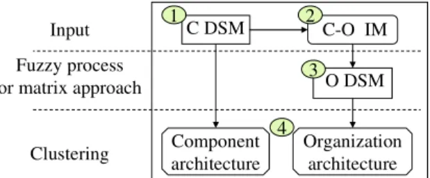
The propagation method is summarized in four steps. First, identify the product architecture by capturing the Component DSM (C DSM). Second, document the Components vs Organization Incidence Matrix (C-O IM). Third, propagate the product architecture choices through the C-O IM in order to generate the Organization DSM (O DSM). Fourth, identify satisfactory organization structure by applying a clustering algorithm (figure 1).
Figure 1 Simulating organization structure starting from the product architecture.
C DSM O DSM C-O IM Component architecture Organization architecture Input Clustering Fuzzy process or matrix approach 1 2 3 4
Step 1: Capture the C DSM. By interviewing system architects who design the
product architecture, the list of components (C) is identified. Then, the authors proceed to identify the design interfaces. System architects have to fill in a square matrix (C DSM) whose rows and columns are identically labeled with the n components of the product. They have to identify and estimate the coupling value concerning the interaction between two components (if it does not exist, the value is null). Typologies for DSM interactions have been identified by Pimmler and Eppinger (1994). In this work, the system architect estimates the coupling value by referring to the set of product attributes (or parameters) that the components affect or share. The same idea is proposed in (Chen et al, 2005). Coupling value is estimated on the scale 0-10.
Step 2: Capture the C-O IM. The assignment relationships between product
components and the design organization teams (or designers) are identified. Firstly, the lists of components identified in the product architecture are used. Secondly, the authors survey the system architects to capture the list of design actors involved in the development of the product. Thirdly, similarly to (Sosa, 2007), this information is documented into a rectangular matrix (C-O IM), whose rows are labeled with the m designers (D) and columns with n components (C). Finally, each IMi,j value is estimated
as the level of involvement of ‘designer i’ in the design of ‘component j’. The value is estimated on the scale 0-10 (0 means that ‘designer i’ is not involved and 10, that he/she is strongly involved). Hence, designers that are involved in the design of the same
component or in the design of two components which share interfaces are likely to collaborate together to ensure the product definition and integration. In this work, an assumption is that the sum of involvement levels for each designer must be inferior or equal to 30. This measure is related to the work load.
Step 3: Simulate O DSM starting from C DSM and C-O IM. The organization
structure is formalized by means of O DSM. This matrix helps to identify the need for information exchanges between designers. Value ‘O DSMu,v’ indicates (or helps to
predict) the degree of dependency between ‘designer u’ and ‘designer v’.
Two approaches can be used to calculate the resulting values of the O DSM: either a fuzzy process or a matrix based approach. Concerning the fuzzy process, some rules are defined as the basis of the propagation method. Axioms are formulated in Section 6. Section 7.3 compares the obtained results with the two methods.
Step 4: Identify Organization structure. The Thebaud clustering algorithm is
applied on O DSM that has been presented above in section 4.2.
6 Simulating O DSM starting from C DSM and C-O IM.
This section first presents a propagation method that has been developed in collaboration with the powertrain design office of a French car manufacturer. Section 6.1 formulates the axioms which are at the basis of the proposed method for simulating a new DSM. Since intensity values inside DSM and IM are quite imprecise and subjective, the use of fuzzy logic is relevant (Zimmerman, 1991; Dubois and Prade, 1980) to manipulate these values. Section 6.2 describes the fuzzy process that computes potential coupling values between each pair of designers. Section 6.3 presents a simple procedure to aggregate the resulting DSM and filter it in order to ignore meaningless values. Section 6.4 describes the latter method that is a matrix-based approach already used by other researchers.
6.1
Axioms
In this section, the axioms that are at the basis of the proposed propagation method are formulated, along with the underlying assumptions.
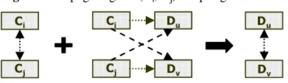
• Axiom 1 (Fig. 2). Two components (Ci, Cj) and two designers (Du, Dv) may be
coupled according to two different ways (symmetrical cases).
• Axiom 2 (Fig. 3). If (Ci, Cj) and (Du, Dv) are coupled and if Ci and Cj interact, then Du
and Dv interact.
• Axiom 3. The intensity of the coupling between Du and Dv is related to both the
coupling value between (Ci, Cj) and (Du, Dv) and the coupling value between Ci and
Cj.
• Axiom 4. An assumption is that each C is coupled to itself with an intensity of maximum value, i.e. 10 (the authors adapt the meaning of the diagonal in the DSM). Figure 2 Coupling a couple of C and a couple of D
&L &M &L &M 'X 'Y 'X 'Y 25 &L &M &L &M 'X 'Y 'X 'Y 25
Figure 3 Propagating the (Ci, Cj) coupling 'X 'Y &L &M &L &M 'X 'Y
Let’s explain the most important axiom, which is Axiom 2. Let us consider that components Ci and Cj interact. If designer Du (resp. Dv) is involved in the design of Ci
(resp. Cj) then he/she is concerned by the definition of Cj (resp. Ci). Designers Du and Dv
are likely to interact to negotiate their component interfaces and conflicting parameters. Axiom 3 assumes that the higher the coupling value between components Ci and Cj and
the higher the involvement level of the designers Du and Dv in the design of these
components, the more these two designers are likely to collaborate each other. Axiom 4 handles the case concerning a Component C directly coupled to (Du, Dv), that means that
the two designers have to collaborate to the design of this component.
6.2
A fuzzy method
A fuzzy propagation method generates n O DSM for each component Ci by
identifying all the potential interactions between designers related to their involvement in the design of Ci or in the design of a component Cj that interacts with Ci. Then it applies
the rules introduced by the axioms and translated into a fuzzy inference system. This system is described hereafter.
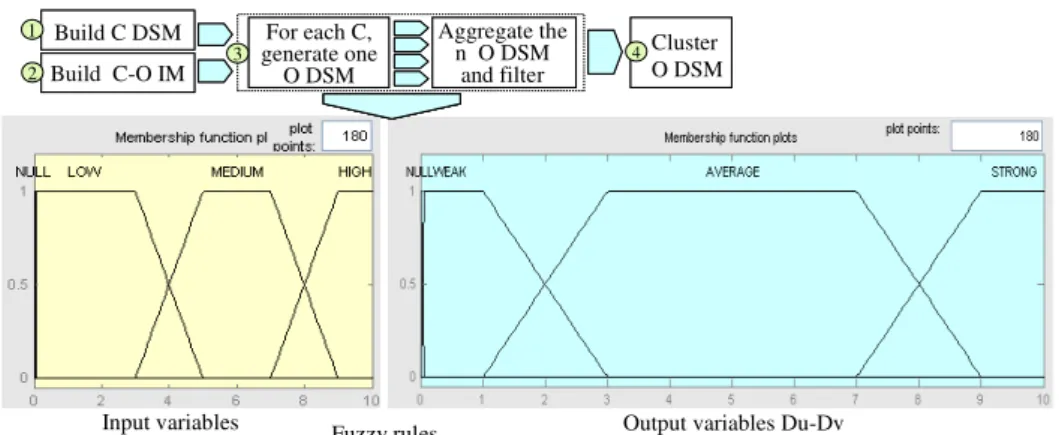
6.2.1. Fuzzification and input membership functions
The “fuzzification” stage corresponds to the transformation of a numerical value through fuzzy variables (input). The structure of the membership functions characterizing the three inputs is chosen by taking into account the architect's reasoning. Four linguistic variables which are Null, Low, Medium and High are defined. The most common membership function, that is, a trapezoidal function, is used. A trapezoidal membership function is used for the fuzzy logic output linguistic variables which are: Null, Weak, Average and Strong (see Figure 4).
6.2.2. Inferences and fuzzy rules
The fuzzy ‘if-then’ rules are developed to relate input to output variables (Zimmerman, 1991). These rules represent the expert’s knowledge about the interactions between input variables and their effects on the output. The inference system approximates the way an architect estimates the coupling between two D. It is based on a set of 20 rules (see Figure 4). This inference system has been implemented with Matlab Toolbox. The objective has been to generate an inference system that is understandable for architects.
6.2.3. Defuzzification and output membership functions
The “defuzzification” stage involves finding a crisp value for the coupling using the output membership function. The aggregated fuzzy output is defuzzified using the “centroid of area” technique. The formula is given in (Dubois and Prade, 1980). This is the most widely adopted defuzzification method, which is reminiscent of the calculation of expected values of probability distributions.
Figure 4 Proposed fuzzy process
Input variables Fuzzy rules Output variables Du-Dv
1. if (Ci-Cj is LOW) and (C i-Du is not NU LL) and (Cj-Dv is not NULL) the n (Du -Dv i s WEAK) (1) 2. if (Ci-Cj is MEDI UM) and (Ci-Du is LOW) and (C j-Dv is not NULL) the n (Du -Dv i s WEAK) (1) 3. if (Ci-Cj is MEDI UM) and (Ci-Du is not NULL ) and (C j-Dv i s LOW ) then (Du -Dv is WEAK) (1) 4. if (Ci-Cj is MEDI UM) and (Ci-Du is MEDI UM) and (Cj-Dv i s MEDI UM) the n (Du -Dv i s AV ERAGE) (1) 5. if (Ci-Cj is MEDI UM) and (Ci-Du is HIGH) and (Cj-Dv is MEDI UM) then (Du -Dv is STRONG ) (1) 6. if (Ci-Cj is MEDI UM) and (Ci-Du is MEDI UM) and (Cj-Dv i s HIGH) then (Du -Dv is ST RONG) (1) 7. if (Ci-Cj is MEDI UM) and (Ci-Du is HIGH) and (Cj-Dv is HIGH) then (Du -Dv is ST RONG) (1) 8. if (Ci-Cj is HIGH) and (Ci-Du is LOW) and (Cj-Dv is LOW) then (Du -Dv is WEAK) (1) 9. if (Ci-Cj is HIGH) and (Ci-Du is LOW) and (Cj-Dv is MEDIUM) the n (Du -Dv i s AV ERAGE) (1) 10. if (C i-Cj is HIGH) and (C i-Du is MEDI UM) and (Cj-Dv is LOW) then (Du -Dv is AV ERAGE) (1) 11. if (C i-Cj is HIGH) and (C i-Du is MEDI UM) and (Cj-Dv is MEDI UM) then (Du -Dv is STRONG) (1) 12. if (C i-Cj is HIGH) and (C i-Du is HIGH ) and (Cj-Dv is HIGH) then (Du -Dv is STRONG ) (1) 13. if (C i-Du is NULL) the n (Du -Dv i s NU LL) (1)
14. if (C j-Dv is NULL) the n (Du -Dv i s NU LL) (1) 15. if (C i-Cj is NU LL) then (Du -Dv is NULL) (1)
16. if (C i-Cj is HIGH) and (C i-Du is LOW) and (Cj-Dv is HIGH) then (Du -Dv i s AV ERAGE) (1) 17. if (C i-Cj is HIGH) and (C i-Du is HIGH ) and (Cj-Dv is LOW) then (Du -Dv is AVERAGE) (1) 18. if (C i-Cj is HIGH) and (C i-Du is MEDI UM) and (Cj-Dv is HIGH ) then (Du -Dv is STRONG) (1) 19. if (C i-Cj is HIGH) and (C i-Du is HIGH ) and (Cj-Dv is M EDI UM) then (Du -Dv is ST RONG) (1)
Build C DSM Build C-O IM For each C, generate one O DSM Aggregate the n O DSM and filter 1 2 3 4 Cluster O DSM
Table 2 summarizes the main features of the fuzzy inference system. The choice of these linguistic variables aims at limiting the influence of low inputs. Tuning the system has been done to choose the more appropriate input-output membership functions and defuzzification method. First, this fuzzy model has been verified with its applications to simple cases whose solutions are known.
Table 2. Features of the fuzzy treatment
And method Min
Or method Max
Implication Min Aggregation Max Defuzzification Centroid
Second, this fuzzy treatment has been tested by applying it to a past engine design. After few changes to the parameters, this fuzzy model has been validated by the system architects since after DSM clustering, the obtained architecture was judged valid. The visual inspection of the clustered DSM with the minimum coupling cost clearly revealed distinctive clusters. They were meaningful and useful for system architects, who recognize and name them easily.
6.3
Aggregate the n C DSM and filter
In order to obtain the aggregated DSM, the average method is used. The intensity of the (Du, Dv) interaction in the aggregated O DSM is computed as follows:
(
)
(
)
(
)
2 n i j v D , u D C , C DSM v D , u D DSM v , u DSM j i ¦¦ = = eq 4The O DSM (size: m x m) obtained through the average method may be dense, because of the density of the IM. The density of the Component DSM (size: n x n) could not be a problem for predicting the dependencies between the designers. But the clustering algorithm used for determining the “satisfactory” architecture may depend on the density of couplings. Thus, values in the aggregated O DSM may need (but it is not necessary) to be filtered low. The filter aims at reducing meaningless coupling values by converting them to zero:
( )
i,j XthenDSM( )
i,j 0 DSMif ≤ = eq 5
where X is a parameter that is automatically fixed by the algorithm so as to obtain a given DSM density.
The clustering algorithm used for determining the “optimal» architecture may be sensitive to the DSM density (number of values that are not null divided by the total number of values). Actually, in the clustering algorithm, the fact of belonging to a module is determined by the highest coupling values and these intensities are not filtered. A key requirement is to preserve at least one interaction for each element. In the following development of this paper, the filter is adjusted in order to obtain DSM with a maximum density of 70%.
6.4
A matrix based method
Several authors use matrix-based methods for representing and managing information regarding project domains and their interactions (Danilovic and Browning, 2007). Sosa (2007) maps a product architecture onto an organization structure. He studied the alignment of product architecture and organizational structure by using a matrix product. Using the same formulation as (Sosa, 2007), that is consistent with the convention used in Section5, denote:
[
]
n , n DSMC a squared matrix whose rows and columns are identically labeled with the n components (C).
[
C-OIM]
m,n a rectangular matrix whose rows are labeled with the m designers (D) that make up the Organization and whose columns are labeled with the n components (C).[
C-OIM]
T n,m transposed matrix The O DSM is computed as follows:[
ODSM]
m,m=[
C-OIM]
m,n.[
CDSM] [
n,n.C-OIM]
Tn,m eq 6 Denote Ci-Cj the coupling value between two components Ci et Cj, and Ci-Du,component Ci (resp. Cj). Note that the dependency value (need for information
exchanges) between Du and Dv concerning the design of a couple (Ci, Cj) may be
computed as follows:
(
)
(Du Ci).(Ci Cj).(Cj Dv) C , C v , u DSM O j i = − − − eq 7That means that the matrix product implicitly assumes that the three variables that have been identified as the inputs of the fuzzy process may be linked by their product.
This section has presented how to simulate O DSM starting from C DSM and C-O IM. For realizing the step 3, two possibilities have been proposed: a fuzzy process and a matrix based approach. The results of the two methods will be compared on the industrial application in section 7.3.
7 Application to an Industrial Context
In this section, the two methods are applied to the definition of new project architectures in the case of a robotized gearbox design. This last one is an incremental and architectural innovation. It is a hybrid gearbox between manual and automatic gearboxes.
7.1
Capturing the initial Product Architecture
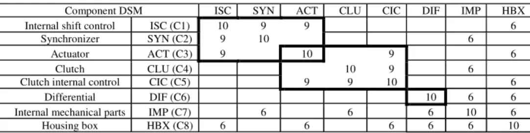
The list of components and their interactions are captured by interviewing system architects who have an expertise in robotized gearbox architecture. The intensity of each interaction has been discussed and fixed according to an existing typology of interactions (Pimmler and Eppinger, 1994). The robotized gearbox is decomposed into eight subsystems (or components) that are in turn decomposable into more than 100 parts. Figure 5 exhibits a component DSM of the so-called gearbox.
Figure 5 Component DSM (C DSM) of the robotized gearbox
Component DSM ISC SYN ACT CLU CIC DIF IMP HBX
Internal shift control ISC (C1) 10 9 9 6
Synchronizer SYN (C2) 9 10 6
Actuator ACT (C3) 9 10 9 6
Clutch CLU (C4) 10 9 6
Clutch internal control CIC (C5) 9 9 10 6
Differential DIF (C6) 10 6 6
Internal mechanical parts IMP (C7) 6 6 6 10 6
Housing box HBX (C8) 6 6 6 6 6 10
The clustering algorithm reveals hybrid architecture, with three modules (or modular sub-systems), and two integrative sub-systems. This architecture has been validated by the gearbox designers since they have adopted the same one. The first module (ISC, SYN, ACT) realizes the shifting function (that is linked to a strategic customer requirement: driving pleasure), the second module (ACT, CLU, CIC) realizes power transmission function. The third module contains only one component which is the differential (DIF). The remaining two components are integrative. They link together all the other modules of the robotized gearbox: IMP (C7) from the inside and the HBX (C8) from the outside.
7.2
Capturing the Incidence Matrix
Incidence matrices are the cornerstone of the present research work. We suppose that the building of an appropriate incidence matrix early in the development process is a key activity of system architects. They need to forecast the impact of their architecture decisions on the management of design teams’ efforts. System architects should predict required interactions between actors who are involved in the product development and then structure the teams efficiently.
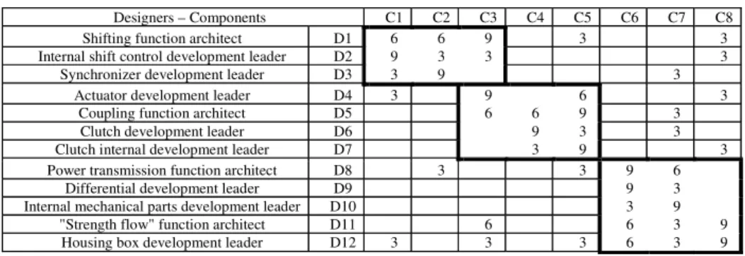
Figure 6 Gearbox components-organization incidence matrix (C-O IM)
Designers – Components C1 C2 C3 C4 C5 C6 C7 C8 Shifting function architect D1 6 6 9 3 3 Internal shift control development leader D2 9 3 3 3
Synchronizer development leader D3 3 9 3 Actuator development leader D4 3 9 6 3
Coupling function architect D5 6 6 9 3 Clutch development leader D6 9 3 3 Clutch internal development leader D7 3 9 3 Power transmission function architect D8 3 3 9 6
Differential development leader D9 9 3 Internal mechanical parts development leader D10 3 9
"Strength flow" function architect D11 6 6 3 9 Housing box development leader D12 3 3 3 6 3 9
The organization responsible for the development of the gearbox is divided into 12 design teams. Each of them is represented by a team leader. There are 8 design teams directly responsible for the development of the 8 components making up the gearbox, 4 function architects responsible for the specification and validation of each system function: gear shifting, coupling, power transmission, strength flow. There is still a project manager responsible for the project management. Two types of interactions are distinguished: technical interactions that directly concern the product design, and coordination efforts that concern the project management. Hence the project manager who has an integrative role from a coordination point of view is removed. The 4 system function architects are surveyed to fill in the Product-Organization incidence matrix. It is a “8 by 12” matrix with, listed in rows, the gearbox components (C) and in columns the development leaders or designers (D) (Figure 6).
7.3
Comparison between the fuzzy process and the matrix approach
The fuzzy process and the matrix approach are applied on the gearbox C DSM and C-O IM, and after using the clustering algorithm, the following two architectures (in Fig. 7 and Fig 8) are obtained. First the authors note that the two methods give the same architecture for the O-DSM. They have asked system architects and component development leaders to visualize DSM and inspect their coherence. Even though this approach is informal and subjective, architectures are often issued from repetitive development experiences and may be judged as being satisfactory. The obtained clusters are satisfactory. The architecture reveals the same three clusters (modules or teams). By analyzing these resulting matrices more precisely, the authors note that:
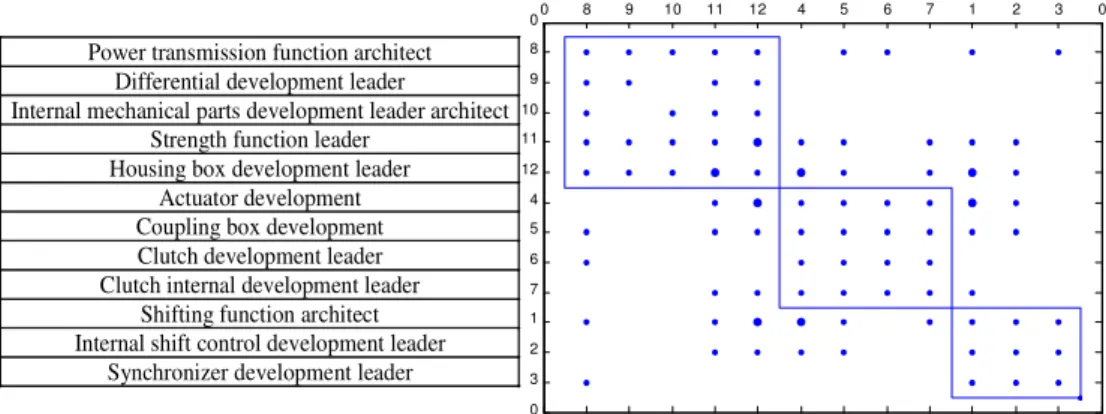
• Module 1: it is the same in the two models. It represents the team designing the differential and the two integrative elements (IMP and HBX): D8, D9, D10, D11, D12.
• Module 2: it corresponds to the team acting on the module achieving the power transmission. It is integral in the case of the fuzzy process. An interaction between D4 and D6 is missing in the case of the matrix approach. Referring to the C-O IM, these designers interact on the clutch internal control only (only one component for three components in this module) but this interaction is required.
Interactions between D8 and D6, or D8 and D3 are missing in the case of the matrix approach (“0” has been added in the cell to highlight the differences). The study achieved in 7.4 can explain this fact.
Figure 7 O DSM, architecture revealed by the fuzzy process
0 8 9 10 11 12 4 5 6 7 1 2 3 0 0 8 9 10 11 12 4 5 6 7 1 2 3 0
Power transmission function architect Differential development leader
Internal mechanical parts development leader architect Strength function leader
Housing box development leader Actuator development Coupling box development Clutch development leader Clutch internal development leader
Shifting function architect Internal shift control development leader
Synchronizer development leader
Figure 8 O DSM, architecture revealed by the matrix-based method
0 8 9 10 11 12 4 5 6 7 1 2 3 0 0 8 9 10 11 12 4 5 6 7 1 2 3 0
Power transmission function architect Differential development leader
Internal mechanical parts development leader architect Strength function leader
Housing box development leader Actuator development Housing box development Clutch development leader Clutch internal development leader
Shifting function architect Internal shift control development leader
Synchronizer development leader 0
0 0
0
0 0
7.4
First discussion
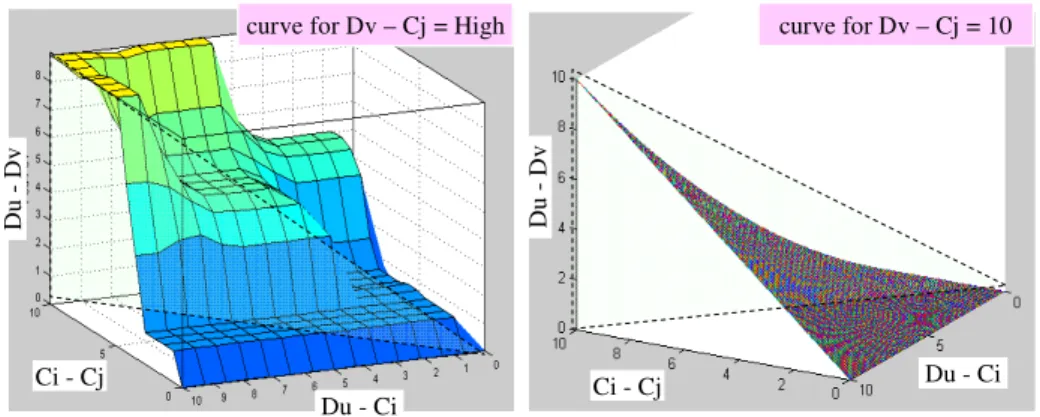
In this example, the fuzzy process has obtained a weak advantage since it succeeds to identify interesting interactions that the matrix approach does not so. These results may be explained. Therefore, the variations of the coupling values are represented according to a 3D curve. Figure 9 represents these functions with the assumptions that Dv-Cj is high (fuzzy process, on the left side) or equals 10 (matrix approach, on the right side).
Figure 9 Variations of the coupling value (Du, Dv) according to (Cj, Dv) and (Ci, Cj) Ci - Cj Du - Ci Du -D v Du - Ci Ci - Cj Du -D v
curve for Dv – Cj = High curve for Dv – Cj = 10
To give a direct comparison between the two functions, a cross section representing F(x,y,z) for x=y=z is made. Two curves are obtained and displayed in Figure 10. A close comparison between these two curves reveals that:
• For low coupling values (0 to 3), the matrix product filters the low values more than the fuzzy process,
• For medium coupling values (4 to 7), the two curves are very different. The fuzzy process gives a step at about 5 whereas the matrix approach tends to lessen (or neglect) the importance of these values. So the fuzzy method is better adapted to take into account the medium coupling values,
• For high coupling values (8 to 10), the two methods give similar results.
These results explain the differences observed in the industrial case. It is rational that more interactions are found in the O DSM obtained by the fuzzy process than in the O DSM obtained by the matrix approach.
Figure 10 Comparison of elementary contributions with the two methods
0 2 4 6 8 10 12 0 1 2 3 4 5 6 7 8 9 10 Fuzzy process Matrix approach
(
)
...for...(Du Ci) (Ci Cj) (Cj Dv) C , C v , u DSM O j i − = − = −7.5
Sensitivity analysis
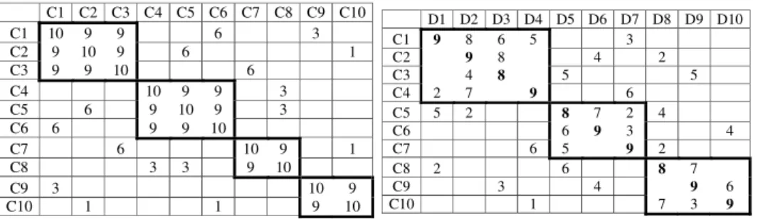
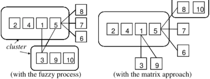
The two methods have been applied to a “didactic case” (Figure 11). Starting from “10 by 10” C DSM and “10 by 10” C-O IM, the O DSM has been computed. The resulting architectures are similar for the two methods.
Figure 11 A virtual case
D1 D2 D3 D4 D5 D6 D7 D8 D9 D10 C1 9 8 6 5 3 C2 9 8 4 2 C3 4 8 5 5 C4 2 7 9 6 C5 5 2 8 7 2 4 C6 6 9 3 4 C7 6 5 9 2 C8 2 6 8 7 C9 3 4 9 6 C10 1 7 3 9 C1 C2 C3 C4 C5 C6 C7 C8 C9 C10 C1 10 9 9 6 3 C2 9 10 9 6 1 C3 9 9 10 6 C4 10 9 9 3 C5 6 9 10 9 3 C6 6 9 9 10 C7 6 10 9 1 C8 3 3 9 10 C9 3 10 9 C10 1 1 9 10
Then a sensitivity analysis is conducted on the obtained architectures. The initial C-O IM is changed, by introducing estimation errors and the obtained architectures are compared. In these simulation experiments, the C DSM values are assumed to be accurate. Estimation errors are introduced into the IM and are modeled as follows:
Denote x, y, z three values sampled from the standard uniform distribution. Denote T1, a threshold that will be considered as a variable for the sensitivity analysis. For a given value in the C-O DSM:
• If x > T1, then there is no error. Otherwise, there is an error,
• If y < 0.75 then the absolute value of the error is 1. Otherwise, it is 2. • If z < 0.5 then the error is negative. Otherwise, the error is positive.
Methodology:
• The reference matrices are defined: C DSM and C-O DSM.
• The reference O DSM is computed and the clustering algorithm is used to reveal the reference architecture for each propagation method (Figure 12).
• The C-O IM values are changed by introducing estimation errors.
• The changed O DSM is computed by the fuzzy process and by the matrix approach. • The clustering algorithm is used to reveal the architecture in the two cases.
• In each case, the obtained architecture is compared to the reference architecture using comparison criteria: the number of elements which are not in the same cluster.
Table 3 shows the results obtained after 20 experiments for each value of T1. For T1=0.8, 2 components have been placed in another cluster in the case of the fuzzy process (40 / 20 experiments, it is a mean of 2) and 2.4 in the case of the matrix approach. The obtained results show that the fuzzy process is less sensitive than the matrix approach regarding this criterion (elements in the same cluster).
Figure 12 Reference architectures after the clustering of the O DSM
(with the fuzzy process) (with the matrix approach)
cluster 10 3 9 6 7 8 5 1 4 2 10 3 9 6 7 8 5 1 4 2 10 3 9 6 7 8 5 1 4 2 10 3 9 6 7 8 5 1 4 2 5 1 4 2 6 7 8 10 3 9 5 1 4 2 6 7 8 10 3 9
Table 3 Results of comparison tests
T1 Fuzzy process Matrix based Method
0.2 12 16 0.4 26 32 0.6 36 44 0.8 40 48 1.0 46 66
7.6
Second discussion
In this section, the interests of these methods are briefly discussed, the comparison results are interpreted and then, some limits concerning this kind of approach are presented.
Interests of the presented methods By propagating product architecture choices
and assignment decisions on the organization domain, a method is proposed to represent and analyzing the sources of complexity (coupling, dependencies) in product development projects. Product architectures can deeply influence design organization structures because product modules are concurrently designed by different design teams.
If design managers are not satisfied with the simulated result, they could change the initial matrix IM and simulate a new organization structure. This last one could be judged better for instance, because the teams may match the functional departments. However, the structures generated by these methods are recommendations. Design managers should be aware that the choice of other teams (i.e. other project organization structure) could increase coordination and teams' integration efforts. The proposed methods could be used to enhance the awareness of designers. They will be able to visualize potential required interactions that they would not able to predict before due to the project complexity.
Comparison The first results presented in this paper indicate that the fuzzy
approach is more adapted to predict potential interactions if there are numerous medium values in the input matrices. In addition, the fuzzy treatment is an advantage to deal with input inaccuracies. Thus the fuzzy method is less sensitive than the matrix based method. However, it is clear that other industrial and academic experiments are necessary to decide if one of the two methods outperforms the other one.
Limits of this approach This paper is complementary to Sosa's work (Sosa, 2007;
Sosa et al. 2003). Sosa compares potential interactions between designers (expected organization DSM obtained by the matrix based method) and the actual information exchanges (actual organization DSM). According to Sosa, identifying mismatches can help managers to steer their attention to interactions that require special attention and efforts. He determines the potential interactions that were unattended by actual
interactions and the actual interactions that were unpredicted by potential interactions. His conclusion is that the propagation methods may help to identify truly unattended interactions between designers that may prevent from integration problems and iterations. But the propagation results may be erroneous. He writes: “truly unpredicted interactions may occur between development actors who interact even though they are not involved in the development of interdependent modules”. Some team interactions may be not predicted by propagating design interfaces. Moreover, indirect interactions are possible when two actors are connecting to a third actor who plays a coordination role. In this case, the expected interactions may be managed by a “transitive” flow of information.
8 Conclusion
The propagation methods presented in this paper compute an O DSM from a given numerical C DSM and a C-O IM. The underlying Organization structure is revealed by means of the Thebaud clustering algorithm. The method proposed in this paper is based on a new fuzzy inference system that generates a DSM. An existing method is based on a matrix product. These methods have been applied to an industrial case and then compared. The proposed method seems to predict potential couplings more efficiently than the matrix based method. A sensitivity study that has been led reveals that the fuzzy process seems to be less sensitive regarding estimation errors in the initial IM. These first results have to be confirmed by further experiments. This paper intentionally applies the method to two project domains. This method may be used similarly to propagate constraints or changes within the product domain (from functional architecture to physical architecture) or from one project domain to another one, for instance, expectation – SF, product – task, task – team. A propagation method should be few sensitive to estimation errors but sensitive to major changes of values explained by architecture changes. Further works will concern the test of the two methods when the goal is to propagate architecture changes and to visualize potential modifications in the other domain.
References
Baldwin C.Y., and Clark K.B. (2000) Design Rules: The Power of Modularity Design, MIT Press.
Bonjour E., Dulmet M., Harmel G. (2008) ‘Mapping Functional Architecture Decisions onto Physical Product Architectures’, INSIGHT, Publication of INCOSE, Vol. 11, No. 3, pp. 8-10.
Bonjour E., Deniaud S., Dulmet M., Harmel G. (2009-a) ‘A fuzzy method for propagating functional architecture constraints to physical architecture’, Transactions of ASME, Journal of Mechanical Design, Forthcoming, Vol. 131, No. 6, June,12p..
Bonjour E., Harmel G., Micaëlli J-P, Dulmet M. (2009-b) ‘Simulating change propagation between product architecture and development organization’, International Journal of Product Development, Forthcoming.
Browning, T.R. (2001) ‘Applying the design structure matrix to system decomposition and integration problems: a review and new directions’, IEEE Trans. Eng. Mgt., Vol. 48, No. 3, pp.
292-306.
Clarkson P. J., Simons C., and Eckert C. (2001) ‘Predicting change propagation in complex design’, Proc. ASME DETC 2001, Paper No DETC2001/DTM-21698, Pittsburgh, PA, USA.
Chen, S.J. and Lin, L. (2003) ‘Decomposition of interdependent task group for concurrent engineering’, Computers & Industrial Engineering, Vol. 44, pp. 435–459
Chen L., Ding Z. and Li S. (2005) ‘A formal two-phase method for decomposition of complex design problems’, Journal of Mechanical Design, March, Vol. 127, No. 2, pp.184-195.
Danilovic M, and Browning T., (2004) ‘A formal approach for domain mapping matrices (DMM) to complement design structuring matrices (DSM)’, In: Proceedings of the 6th International Design Structure Matrix (DSM) workshop, Cambridge, UK, September 12–14.
Danilovic, M. and Browning, T.R. (2007) ‘Managing complex product development projects with design structures matrices and domain mapping matrices’, International Journal of Project Management, Vol. 25, pp.300–314.
Dubois D., Prade H. (1980) Fuzzy sets and systems: Theory and applications. Academic Press
1980.
Dunn T.P., and Sussman J.M. (2006), ‘Design Structure Matrices to Improve Decentralized Urban Transportation Systems’, Transportation Research Record, pp. 193-200.
Eichinger M., Maurer M, Pulm U., Lindemann U. (2006) ‘Extending Design Structure Matrices and Domain Mapping Matrices by Multiple Design Structure Matrices’, Proc. 8th Biennial Conf. on Engineering Systems Design and Analysis (ASME-ESDA06), Torino, Italy, July 4-7. Eppinger, S.D., and Salminen, V. (2001) ‘Patterns of product development interactions’, Int. Conf.
on Engineering Design, ICED 01, Vol. 1, Glasgow, August 21-23, pp.283-290.
Fernandez, C. (1998) Integration analysis of product architecture to support effective team co-location. Master of Science Thesis, MIT, USA.
Farrell S., and Simpson T.W. (2008) ‘A Method to Improve Platform Leveraging in a Market Segmentation Grid for an Existing Product Line’, ASME Journal of Mechanical Design, Vol.
130, No.3, 031403 (11 pages)
Fixson, S.K. (2005) ‘Product architecture assessment: a tool to link product, process and supply chain design decisions’, Journal of Operations Management, Vol. 23, pp.345-369
Gu P., and Sosale S., 1999, ‘Product modularization for life cycle engineering’, Robotics and Computer Integrated Manufacturing, Vol. 15, pp. 387-401.
Hartigan J. (1975) ‘Clustering Algorithms’, 1975 (Wiley & Sons, New York, NY).
Idicula, J. (1995) Planning for concurrent engineering, Thesis draft, Nanyang Technology
University.
IEEE Std 1220™, Standard for application and Management of the Systems Engineering Process. IEEE Computer Society, Revision of IEEE Std 1220-1998, 2005.
Jiao J., Simpson T., Siddique Z. (2007) Product family design and platform-based product development: a state-of-the-art review. Journal of intelligent manufacturing, special issue on Product family design and platform-based product development, Vol. 18, No.1, pp. 5-29, 2007. Kurtoglu T., and Tumer I.Y. (2008) ‘A graph-based fault identification and propagation Framework for functional design of complex systems’, ASME Journal of Mechanical Design, Vol. 130,
No. 5, 051401 (8 pages).
Liu Y., Chakrabarti A. and Bligh T.P. (1999) ‘Transforming Functional Solutions into Physical Solutions’, Proceedings of the ASME Design Theory and Methodology Conference, DETC/DTM-8768, 12-16 September, Las Vegas, NV.
Lindemann, U. (2007) ‘A vision to overcome chaotic ‘design for X’ processes in early phases’,
Proceedings of International Conference on Engineering Design, ICED’07, Paris, August,
Vol. F, pp.28–31.
Meier C., Yassine A., and Browning T., (2007) ‘Design process sequencing with competent genetic algorithms’, Journal of Mechanical Design, Vol. 129, No. 6, 566 (20 p.).
Pimmler, T. U. and Eppinger, S. D. (1994) ‘Integration analysis of product decompositions’,
Proceedings ASME Design Theory and Method Conference (DTM'94), Vol. 68, pp. 343-351.
Sharman, D. and Yassine, A. (2004) ‘Characterizing complex product architectures’, Systems Engineering, Vol. 7, No. 1, pp. 35-60.
Sharman D. and Yassine A. (2007) ‘Architectural Valuation using the Design Structure Matrix and Real Options Theory’, Concurrent Engineering, Vol. 15, No. 2, pp. 157-173.
Sosa, M.E., Eppinger, S.D. and Rowles C.M. (2000) ‘Designing modular and integrative systems’,
Proceedings of DETC '00: ASME 2000 Int. Design Engineering Technical Conferences.
Sosa, M., Eppinger, S. and Rowles C. (2003) ‘Identifying modular and integrative systems and their impact on design team interactions’, Journal of Mechanical Design, Vol. 125, pp. 240-252
Sosa M. (2007) ‘Aligning process, product, and organizational architectures in software development’, Int. Conf. Engineering Design, ICED’07, 28-31 August, Paris.
Sosa M., Eppinger S. and Rowles C. (2007) ‘A network approach to define modularity of components in complex products’, Journal of Mechanical Design, Vol.129, No.11, pp.
1118-1129.
Steward, R. P. and Donald V. (1981) ‘The Design Structure System: A Method for Managing the Design of Complex Systems’, IEEE T. on Engineering Management Vol. 28, No.3, pp. 71-74.
Stone, R., Wood, K. and Crawford, R. (2000) ‘A heuristic method for identifying modules for product architectures’, Design Studies, Vol. 21, pp.5-31.
Suh, N. (1990) Principles of Design, Oxford University Press, Cambridge, UK.
Thebeau R. (2001) Knowledge management of system interfaces and interactions for product development processes. Master of Science Thesis, MIT.
Ulrich K.T., (1995) ‘The Role of Product Architecture in the Manufacturing Firm’, Research Policy, Vol. 24, pp. 419-440.
Ulrich K.T. and Eppinger S.D. (2000) Product Design & Development, 2000 (2nd Ed.
McGraw-Hill, New York).
Whitfield, R.I., Smith, J.S. and Duffy, A.H.B. (2002) ‘Identifying Component Modules’, In Proceedings of Seventh International Conference on Artificial Intelligence in Design (AID’02), Cambridge, United Kingdom, pp. 571-592.
Yassine, A. and Braha, D. (2003) ‘Complex concurrent engineering and Design Structure Matrix method’, CERA, Vol. 11, No. 3, pp. 165-176.
Yu, T., Yassine A. and Goldberg D. (2003) ‘Genetic algorithm for developing modular product architectures’, In Proc ASME 15th Int Conf Des Theory Methodology, Chicago, September.