Ecodesign Criteria For Composite Materials And Products
12
0
0
Texte intégral
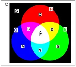
(2) B. Attaf. J. Fundam Appl Sci. 2013, 5(1), 69-80. 70. This is due to their significant and attractive advantages in terms of high strength and stiffness coupled with mass savings, and other tremendous properties that cannot be reached with conventional materials [4-5]. In addition to these technically qualitative advantages, the notion of designing environmentally-friendly composite materials and products must be considered in all design stages [6-9]. Within this context, the environmentally conscious designers have to factor in the impacts of their products on the environment and find new practical solutions with healthier working conditions and fewer VOC (Volatile Organic Compound) emissions. Typically, these solutions are based on new criteria in the form of environmental and health coefficients, which are called later on “eco-coefficients” while ecological requirements are taken into account [10-11]. These eco-coefficients are to be inserted into the classical lamination theory to come up with new ecodesign strategy that include sustainable formulations (ecoformulations) and cleaner production, so as to be in compliance with new regulations and still make the product more competitive in the worldwide composite market. By adopting this strategy in the context to go green can help composite companies to boost innovation, creativity and competitiveness. Some of these alternative issues include (i) reduction of VOC emissions and costs, (ii) use of non-toxic chemicals, (iii) use of no carcinogenic substances, (iv) generation of products with low emission of greenhouse gases, and so forth.. 2. RESEARCH STRATEGY AND METHODOLOGY 2.1 Ecodesign model The diagram shown in Fig. 1 represents the ecodesign model as an interaction between Quality, Health and Environment aspects (i.e. Q, H and E, respectively). This interaction . yields a certain number of subsets. However, only subset F is fulfilling the required condition of ecodesign. The three dots () above the character “F” are only a brief description of the diagram illustrated in Fig. 1, showing interaction between Q, H and E aspects (i.e.,. ). In other terms, the three dots represent the three pillars that characterize the. basic elements of the sustainable development concept [10-11]..
(3) B. Attaf. J. Fundam Appl Sci. 2013, 5(1), 69-80. 71. Fig. 1: Attaf’s Model of ecodesign concept. 2.2 Application of probability approach . To evaluate the number of chances providing the realization of the event F , it is necessary to use the notion of probability. The event and the associated probability expressions can respectively be written as [10, 11]: . F =QHE. (1). . P( F ) = P(Q H E). (2). According to the dependency of sets Q, H and E and the rules of multiplication in the probability theory, Eq.(2) can be written as follows: . P( F ) = P(Q) PQ (H) PQH (E). (3). As the ecodesign process depends on the probability value expressed by Eq.(3), it is convenient to assign to each of Q, H and E aspects a specific coefficient representing the probability of approval. It may therefore be considered that: . α = P(Q) is an eco-coefficient representing the probability of approval in terms of quality assurance;. . β = PQ (H) is an eco-coefficient representing the probability of approval with regard to health protection and known that quality is achieved; and. . γ = PQH (E) is an eco-coefficient representing the probability of approval with regard to environmental preservation, known that health and quality are achieved..
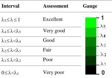
(4) B. Attaf. J. Fundam Appl Sci. 2013, 5(1), 69-80. 72. Mathematical product of the above-mentioned coefficients can consider the greening condition for the green design. For notation simplicity, the quantity obtained by multiplication rule may be represented by a single variable called “eco-factor” and denoted by the Greek letter . According to Eq.(3), this latter can be written as: = . (4). This eco-factor will be used to provide better assessment of Q-H-E performance in relation to each stage involved in the design process. For instance, if the eco-factor approaches unity (100%), the process used in that stage is fully satisfying the green design requirements and ensuring its sustainability. However, if the eco-factor is not close to the target value required by sustainability standards, we need to search for possible new alternatives that provide new eco-coefficients and then new derived eco-factor. Table 1 recapitulates the assessment operation for different intervals and shows a rating satisfaction measure in the form of color gauges. Table 1. Probability color gauges for different values of eco-factor Interval. Assessment. 5 1. Excellent. 4 <5. Very good. 3 <4. Good. 2 <3. Fair. 1 <2. Poor. 0 <1. Very poor. Gauge. 3. ECO-FORMULATIONS AND CONSTITUTIVE EQUATIONS 3.1 Eco-characterization of composite materials The mechanical properties of the selected composites are determined after several tests of tensile, compression, bending, twisting, delamination, buckling, fatigue, control of fiber volume fraction, etc. The classical values obtained are compared with sustainable values that are taking into account environmental and health considerations, which are determined by an.
(5) B. Attaf. J. Fundam Appl Sci. 2013, 5(1), 69-80. 73. eco-characterization approach [12] and optimization procedure for the ecodesign function. Thus, the Young’s moduli E1, E2, E3 and the shear moduli G12, G23, G13 of the composite material determined and derived from experimental results must be adapted to the actual situation by integrating health and environmental considerations into characterization tests. . . . . . . Consequently, the new eco-moduli will become E 1 , E 2 , E 3 , G 12 , G 23 , G 13 where the three dots above the characters E and G are only a brief description of the diagram illustrated in Fig. 1 as discussed earlier in section 2.1.. In relation to this orientation and for a unidirectional fiber-reinforced orthotropic ply, the ecofactors related to the elastic moduli for the linear mechanical behavior may be defined in the principal coordinate system as [12]: . . G E i i , ij ij Gij Ei. . . E E and i j ij ji. (i,j=1,2,3 and i j ). (5). . Where, Ei, E i are classical and sustainable Young’s moduli in i-direction (i=1, 2 and 3); . Gij, G ij are classical and sustainable shear moduli in the i-j plane (i-j=2-3, 3-1 and 1-2); i, ij are the eco-factors of Young’s and shear moduli, respectively and ij is the Poisson’s ratio for transverse strain in the j-direction when stressed in the i-direction. It should be noted that in this analysis, no investigation was made to obtain sustainable values of Poisson’s ratios. According to generalized Hooke’s law and for a plane stress (3 = 23 = 31 = 0), the strainstress relations for an orthotropic material in the principal coordinate system (1,2) may be written in compact matrix form as:. . S ij 1,2 1,2 1,2. (i,j=1,2,6). (6). Where, Sij is the eco-compliance matrix of order 33 (3 rows by 3 columns). The . . . elements Sij S ji are defined by the following expressions: S 11 1 E1. . S 12 . 12 . E1. . 21 . E2. . . S 16 S 61 0. S 22 1 E2. S 66 1 G12.
(6) B. Attaf. J. Fundam Appl Sci. 2013, 5(1), 69-80. 74. Furthermore, the eco-stiffness matrix of a ply may be obtained by the inverse of the ecocompliance matrix. Thus, we can write: Q S ij ij . -1. (i,j=1,2,6). (7). When using the eco-stiffness matrix, expressed by Eq.(7), the inverse relation of Eq.(6) can be written in compact matrix form as:. Q ij 1,2. 1,2. . (i,j=1,2,6). 1,2. (8). Using the transformation matrix from principal coordinate system (1,2) to general coordinate system (x,y), Eq.(8) may be written as: Qij x, y x, y. . (i,j=1,2,6). x, y. (9). The terms Qij (i, j = 1, 2, 6) are functions of the fiber orientation angle, , and the orthotropic elastic eco-moduli of the lamina. By letting C=cos and S=sin , these terms are defined as: . . . . . Q11 Q11C 4 2(Q12 2Q 66)S 2C 2 Q 22 S 4 . . . . . . . Q12 (Q11Q 224Q 66)S 2C 2 Q12(S 4 C 4) . . . . . . . . . . . . . . . . . . . Q16 (Q11Q122Q 66)SC 3 (Q12Q 22 2Q 66)S 3C Q26 (Q11Q122Q 66)S 3C (Q12Q 22 2Q 66)SC 3. . Q22 Q11 S 4 2(Q12 2Q 66)S 2C 2 Q 22 C 4. . . . Q66 (Q11Q 222Q122Q 66)S 2C 2 Q 66(S 4 C 4). 3.2 Constitutive equations When the Environment and Health impacts besides Quality are taken into consideration in the structural analysis, the constitutive relations for an unsymmetrically n-layered laminates with transverse shear deformations can be written in compact matrix form as: N Aij Bij 0 0 M Bij Dij 0 Q x, y x, y 0 0 F ij . For which,. . . n. zk. k 1. z k 1. . (Aij , Bij , Dij ) (Qij )k (1, z, z 2) dz . n. F ij α ij k 1. zk. z k 1. (10). . (Q ij ) k dz. (i,j=4,5). (i,j=1,2,6).
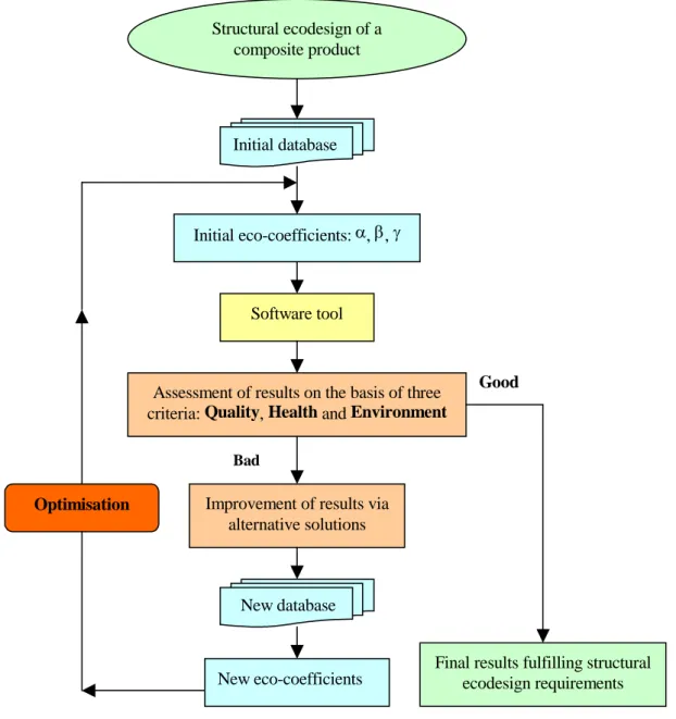
(7) B. Attaf. J. Fundam Appl Sci. 2013, 5(1), 69-80. . 75. . where: { N } is the in-plane eco-forces vector; { M } is the bending/torsional eco-moments . vector; { Q } is the out-of-plane eco-forces vector; {0} is the mid-plane strains vector; {} is . the curvatures vector; {} is the transverse shear strain vector; [ Aij ] is the extensional eco. . stiffness matrix; [ Bij ] is the coupling eco-stiffness matrix; [ Dij ] is the bending eco-stiffness ___. . . matrix; [ F ij ] is the transverse shear eco-stiffness matrix; [ Qij ] is the ply eco-stiffness matrix in the xyz coordinate system and ij is the transverse shear correction factor.. 3.3 Finite element eco-method When the analytical or mathematical solution does not exist, numerical methods such as finite element method may be used to yield an approached solution. However, to achieve sustainable structural performance that is also based on an assessment of environmental and health performances, it is imperative to consider these constraints in more detail and integrate them into the finite element formulations. The formulations for finite element eco-method are derived and presented in further work.. 3.4 Flowchart software The optimization process for structural ecodesign and analysis of composite products is represented by a flowchart (Fig.3), where the results are assessed after each loop for the stage k (k=1, 2, .., N) on the basis of the three main criteria (i.e., Q, H and E). For instance, if the final output results are not close to the objective required by the ecodesign requirements, we need to search for possible new alternatives that provide new data and then new ecocoefficients. Moreover, comparing the eco-results with the classical ones that do not take into account environmental and health considerations can yield an estimate difference value called in this analysis “eco-deviation”, which may be calculated using the following relation: . Eco-deviation (%) V V 100 V. (11).
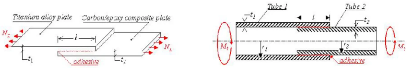
(8) B. Attaf. J. Fundam Appl Sci. 2013, 5(1), 69-80. 76. . where V is the eco-result corresponding to specific value of the eco-factor i (variable from 0 to 1) and V is the classical result corresponding to =1.. Structural ecodesign of a composite product. Initial database. Initial eco-coefficients: , , . Software tool. Assessment of results on the basis of three criteria: Quality, Health and Environment. Good. Bad. Optimisation. Improvement of results via alternative solutions. New database. New eco-coefficients. Final results fulfilling structural ecodesign requirements. Fig. 2: Process flowchart for ecodesign of a composite product (stage k). 4. RESULTS AND DISCUSSION FOR SOME CASE STUDIES 4.1 Example 1: Eco-bonded structures with a single-lap adhesive joint To be familiar with the ecodesign approach, let us consider for example an adhesively-bonded composite structure [13] as shown in Fig.3, where its components were assembled together using adhesives with high amount of VOC emission and a traditional bonding process. In such situation, operators are physically exposed to manipulate harmful substances..
(9) B. Attaf. J. Fundam Appl Sci. 2013, 5(1), 69-80. 77. Fig.3: Bonded structures with a single-lap adhesive joint: (a) two plates; (b) two tubes. . Using the eco-factor, derived above and expressed by Eq.(5), the ecobonding shear stress c , for the case shown in Fig.3a, can be written as:. a aGa tc . . 10 1 20 1 10 E th l E sh l ch x E sh x 2 1 1 . (12). where, 2 aGa 1 1 ta E1 t1 E2 t2 . The assessment of the adhesively-bonded composite plates (Fig.3a) in terms of Q-H-E performance is shown in Fig.4. 25.00 20.00. _______ __________ __________ __________ __________. 16.00. a (MPa). 12.00. a = 1 a = 0.8 a = 0.6 a = 0.4 a = 0.2. 20.00. 15.00. 10.00. 8.00. 5.00. 4.00. 0.00. 0.00 0.00. 10.00. 20.00. 30.00. 40.00. 0.00. 0.20. 0.40. x (mm). . 0.60. 0.80. 1.00. (b). (a). Fig. 4: Adhesively-bonded composite plates: (a) Shear stress distribution vs. adhesive joint . lap length; (b) Normalized relationships between = a /a and =x/l, for different values of a.
(10) B. Attaf. J. Fundam Appl Sci. 2013, 5(1), 69-80. 78. 4.2 Example 2: Vibrational eco-analysis of composite plates Let us consider a simply supported laminated plate with layers symmetrically arranged about the middle surface. Consequently, bending-extension coupling (Bij) and twist coupling (D16 , D26 ) are all equal to zero. Thus, the natural eco-frequencies for free vibration may be written in the following form: . f mn 2 . . . . 1. 2 2 4 2 m 4 m n D n D 2 ( D 2 D ) 11 12 66 22 a a b b . (13). where, the integers m and n correspond to half-waves in x and y directions, respectively. The effect of the eco-factor i on the plate first natural frequency is represented in Table 2, where the estimate difference value (eco-deviation) in the natural frequency was calculated using Eq.(11). . Table 2: First natural eco-frequency f11 for different values of I Eco-factor i 1 0.8 0.6 0.4 0.2. . Eco-frequency f11 (Hz) 480.96 430.18 372.55 304.18 215.09. Eco-deviation (%) 0.00 10.56 22.54 36.76 55.29. 5. RECOMMENDATIONS AND CONCLUSION Since composite companies are very concerned by the ecodesign strategy and the implementation of an environmental management system (EMS), they are therefore encouraged to move towards the optimization of the ecodesign function in order to green up their products and services. In this environmentally mindful context, our innovative methodology will be adapted to the requirements of the major prime contractors involved with manufacturing composite materials and products, including those dealing with conventional and traditional materials. The methodology can be of interest to all existing market segments, namely: (i) civil engineering (housing and green building); (ii) mechanical engineering; (iii) aeronautics & space; (iv) shipbuilding; (v) automotive; (vi) renewable energy (wind and solar); (vii) nano-composites and medicine, and so forth..
(11) B. Attaf. J. Fundam Appl Sci. 2013, 5(1), 69-80. 79. The greatest benefit comes to composite companies that contemplate improving their percentage-point success rate in innovation, creativity and competitiveness. The output data processing results can help these companies to survive in the competitive international composite market. On the other hand, our innovation will integrate existing international and European efforts that support environmental performance improvement and assist them in developing sustainability research actions in compliance with new legislations on environment preservation and health protection whilst taking into account quality assurance requirements. It effectively responds to the needs of major clients and end-users involved in new composite products that take into account all the impacts associated with their life cycle. In addition, this innovation in composite materials and associated products reflects the concept of environmental management and the spirit of scientific research activities in the world wide.. 6. REFERENCES [1]. Jones R.M. Mechanics of composite materials, 2nd ed., Taylor & Francis Ltd., Philadelphia 1999. [2]. Chung Deborah D.L. Composite materials, 2nd ed., Springer-Verlag Ltd., London 2010. [3]. Attaf B. (Ed.) Advances in composite materials for medicine and nanotechnology, InTech Open Access Publisher, Rijeka 2011. [4]. Strong A.B. Fundamentals of composites manufacturing: materials, methods, and applications, 2nd ed., Society of Manufacturing Engineers, Michigan 2008. [5]. Attaf B. and Bachène M. Effects of geometric ratios and fibre orientation on the natural frequencies of laminated composite plates. J. Fund. App. Sci., 2(2), 2010, 114.. [6]. Sharma V.P. et al. Polymer composites sustainability: environmental perspective, future trends and minimization of health risk. 2nd International Conference on Environmental Science and Development, IPCBEE vol.4, IACSIT Press, Singapore 2011, pp. 259-261. [7]. Aly M. (2012). Development of an eco-friendly composite material for engineering applications. PhD thesis, Dublin City University.. [8]. Attaf B. (Ed.) Advances in composite materials: ecodesign and analysis, InTech Open Access Publisher, Rijeka 2011.
(12) B. Attaf. J. Fundam Appl Sci. 2013, 5(1), 69-80. 80. [9]. Attaf B. Eco-moulage des pales d’éoliennes et panneaux solaires en matériaux composites via la technologie RTM. J. Fund. App. Sci., 2(1), 2010, 35-46.. [10]. Attaf B. Towards the optimisation of the ecodesign function for composites. JEC Composites 34, Paris 2007, pp. 58-60.. [11]. Attaf B. Generation of new eco-friendly composite materials via the integration of ecodesign coefficients. In Brahim Attaf (ed.), Advances in composite materialsEcodesign and analysis. Intech Open Access Publisher, 2011, p.1-20.. [12]. Attaf B. Eco-characterisation of Composite Materials. JEC Composites, n° 42, Paris 2008, pp.58-60.. [13]. Gay D. Matériaux composites. 2ème édition. Paris: Hermes, 1989, p. 497-508.. How to cite this article Mahfoudi N and Kdaja M. Thermodynamic modelling of a pistons engine: calculation of the nox emissions. J Fundam Appl Sci. 2013, 5(1), 69-80.
(13)
Figure
Documents relatifs
Key words: Sliding mode control, hyperbolic equations, robust control, stabilization of PDEs, nonlinear systems..
The fission barriers standing in the quasi-molecular shape path have been de- termined within a generalized liquid drop model taking into account the nuclear proximity energy, the
8 , familial aggregation of disease would be different for exposed and unexposed indexes if the environmental factor studied is involved in GxE interaction.. A rational for
Chapter 2 of [18] presents an introduction to the MapReduce paradigm. In particular, it includes the MapReduce algorithm for cascade joins that we en- hance with privacy
139 Suggestions for a Conceptual Approach
In this work we focus on a specific set of pred- icates in LOD datasets that indicate entity type information. For a target entity, we collect all indi- dated types. In detail, we
Compared criteria are: Best Practise (BEST), Last Ply Failure with mRoM (mRoM) and MFH (MFH) degradation method without residual ther- mal stresses and with thermal stresses (mRoM
First of all, almost 90% of the companies responded that they consider sustainability in NPD. However, the definitions of sustainability differ from company to company and most
