Thermo-economic optimization during
preliminary design phase of organic
Rankine cycle systems for waste heat
recovery from exhaust and recirculated
gases of heavy duty trucks
L. GUILLAUMEa, A. LEGROSa, R. DICKESa, V. LEMORTa
a Thermodynamics Laboratory, University of Liège, Campus du Sart Tilman, B49,
B-4000 Liège, Belgium
Contact: [email protected]
ABSTRACT
Waste heat recovery (WHR) Organic Rankine Cycle (ORC) system is a very promising technology for reducing fuel consumption and consequently the CO2 emissions of future heavy-duty trucks (HDT). Nonetheless, the adoption of this technology in the automotive domain requires specific R&D activities going from the system definition to the on-board integration. This study focuses on the preliminary design phase of ORC systems recovering the heat wasted from two of the sources available on a HDT: the exhaust and recirculated gases. From these heat sources and their combinations, 6 possible architectures are identified. On the other hand, 4 volumetric expansion machine technologies are considered (scroll, screw, piston and vane Expanders). At the end, 24 topologies are therefore modelled considering the main components (Pump, Heat exchangers, Expansion machines). A three-step optimization method is proposed to identify the most promising system. First, the most suitable conditions are identified for the design of the ORC systems using a simple model of volumetric expansion machine. In a second step, the design phase, using more detailed models for the expansion machines, a thermos-economic optimization is performed. Finally, in a third step, the output power of the latter system models is maximized in off-design conditions, optimizing the evaporating pressure and the overheating degree.
KEYWORDS: Organic Rankine Cycle, Waste Heat Recovery, Heavy Duty Trucks,
NOMENCLATURE
SYMBOLS SUBSCRIPTS
A Heat transfer area [m²] cd Condenser
Bo Boiling number [-] co Corrugation
C Empiric coefficient [-] or Cost [€] cond Conduction
D Diameter [m] conv Convection
DC Direct cost [€] cp Compressor
e Plate thickness [m] ctrl control
F Coefficients in Martin's correlation [-] EG Exhaust Gas
f Fanning friction factor [-] EGR Exhaust Gas Recirculation
G Mass velocity [kg/s.m²] Eng Engineering
h Specific enthalpy [J/kg] eq Equivalent
IC Indirect cost [€] ev evaporator
k Thermal conductivity [W/m.K] ex Exhaust
L Plate length [m] exp Expander 𝑴̇ Mass flow rate [kg/s] h Hydraulic
m Empiric coefficient [-] instl installation
mu Dynamic viscosity [Pa.s] l Saturated liquid
n Empiric coefficient [-] liq Liquid
N Rotational speed [RPM] LT Low temperature
Nu Nusselt number [-] p piping
P Pressure [pa] pp Pump
p Pitch [m] rot rotational
Pr Prandtl number [-] s swept or isentropic 𝑸̇ Heat flow rate [W] su Supply
Re Reynolds number [-] syst System
T Temperature [°C or K] tp Two-phase
SIC Specific investment cost [€] v Saturated vapor
TIC Total investment cost [€] vap Vapor
U, h Heat transfer coefficient [W/m².K] wf working fluid
V Volume [m³]
𝑾̇ Mechanical or electrical power [W]
x Vapor mass fraction [-]
GREEK SYMBOLS
𝜷 Chevron angle [rad] 𝝐 Efficiency [-] 𝝆 Density [kg/m³]
1. INTRODUCTION
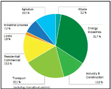
It is now accepted that greenhouse gas emissions from human activities are enhancing the global warming effect keeping the earth at a temperature higher than it would otherwise be (1). In the last twenty years, the World energy consumption has increased by more than 30% (2) despite the adoption by the United Nations on Climate Change of the Kyoto Protocol (3). In 2012 (Figure 1) the transport sector was responsible of about one third of the European CO2 emissions. And it was pointed out that "Heavy-Duty Vehicles (HDV) represent about a quarter of EU road transport
improvements in fuel consumption efficiency, HDV emissions are still rising, mainly because of the increasing number of vehicles in traffic. Nowadays, HDV are the second biggest source of emissions within the transport sector, i.e. larger than both international aviation and shipping. Thus, the reduction of these CO2 emissions has become a strategic goal of the EU.
A very promising solution is the valorization of the waste heat, which is about 60% of the combustion energy, transforming it into mechanical or electrical energy to increase the overall vehicle energy efficiency and consequently reducing its CO2 emissions and fuel consumption. The heat re-use can be performed by means of a heat engine (e.g. organic or steam Rankine cycle systems) using the waste heat as energy source, as it is being adopted for large stationary applications. The adoption of such technology in the automotive domain requires specific R&D activities in order to identify the most appropriate system architecture and integration level so to achieve sustainable cost and the reliability requirements. A major part of these activities is dedicated to the selection of the working fluid and the expansion machine. The working fluid selection process has been widely investigated in several studies (6,7,8,9,10,11) but no universal optimal fluid is indicated since the choice is highly dependent to the target application. A detailed list of the guidelines and indicators that should be considered when selecting an organic fluid for power generation are reported in (9).
This study focuses on volumetric expansion machines and particularly on the scroll, screw, piston, and vane technologies for which experimental data is available. Numerous design steady-state models of ORCs are built. Using these models, a three steps optimization method is proposed starting with the selection of the design conditions. Then, for these conditions, a thermo-economic optimization is performed to design the systems. Finally, the performance of the systems is optimized and evaluated in off-design conditions, optimizing the evaporating pressure and the overheating degree.
2. DEFINITION OF THE CASE STUDY
This paper attempts to address this problematic of selecting the architecture, the expander technology, and the working fluid for a waste heat recovery organic (or non-organic) Rankine cycle system devoted to be coupled to a truck engine. In a first step, the use case is defined in terms of investigated heat sources and heat sinks, working fluid candidates, technologies of the ORC components and engine operating conditions on which the system will be designed and its performance will be evaluated.
2.1 Heat sources and heat sinks
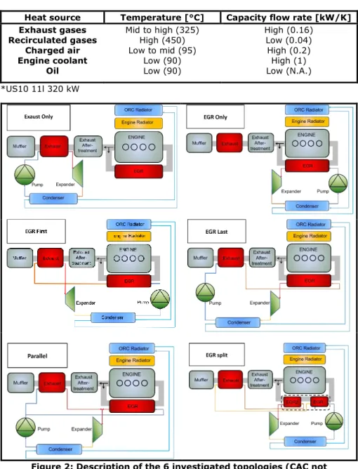
Multiple heat sources can be considered to recover the thermal energy wasted by the engine. A list of the potential heat sources available on a truck equipped with an Exhaust Gas recirculation (EGR) system is given in Table 1. In this table, the temperature levels of the heat sources and their capacity flow rates are compared. Because, increasing the number of sources will increase the level of complexity in terms of packaging and control and the cost of the system, it is proposed, in this study, to investigate only two heat sources. In (12), a second law analysis is performed and shows, based on the work performed in (13) and (14), that the most interesting sources are the exhaust gases, and the recirculated gases, to which correspond the highest temperature levels. The charged air is not considered since a modification of its temperature level might largely affect the performance of the engine.
The only heat sink available on a truck is air, the ram air created by the vehicle movement and the air pulsed by the fan. The vehicle cooling module, usually composed of the air conditioning (A/C) condenser, the charge air cooler (CAC), the main engine radiator and the cooling fan, uses this air as secondary fluid for the different heat exchangers. Because of space constraints, adding a new heat exchanger (direct condenser or a radiator dedicated to an indirect condenser) in the front end of the truck is challenging. Moreover, the limited heat rejection capacity margin of the cooling module as well as the additional pressure drops resulting from the insertion of an additional heat exchanger in the cooling module are constraining the heat recovery and might lead to an engagement of the fan, which consumes a lot of energy. A configuration without excessive fan power consumption, due to the ORC system, is the use of the engine coolant in order to feed an indirect condenser as studied in (14). Innovative solutions such as the increase of the heat rejection capacity using part of the body panels as heat exchangers (flat heat exchangers) functionalizing the aerodynamic under-body and of part of the side body panels were proposed (15) but might be more complex to implement. Finally, another possibility, the one retained in this study, is the use of a low temperature radiator dedicated to the Rankine condenser and placed between the charge air cooler and the engine radiator. This configuration leads to an increase in net output power of the WHR system of about 11% compared to the use of the engine coolant (12).
Combining the two investigated sources and the single heat sink, 6 possible topologies are identified for this study. They are shown in figure 2.
Table 1: Description of the heat sources available on the investigated truck*
Heat source Temperature [°C] Capacity flow rate [kW/K] Exhaust gases Recirculated gases Charged air Engine coolant Oil Mid to high (325) High (450) Low to mid (95) Low (90) Low (90) High (0.16) Low (0.04) High (0.2) High (1) Low (N.A.) *US10 11l 320 kW
Figure 2: Description of the 6 investigated topologies (CAC not represented)
2.2 Working fluid candidates
Hundreds of working fluids are available on the market and the selection of working fluids has been treated widely in scientific publications. Most of the time, a comparison between a set of candidate working fluids in terms of thermodynamic performance and based on a thermodynamic model of the cycle is proposed. Quoilin
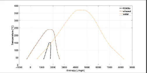
(16) proposed some guidelines and indicators (thermophysical properties, thermodynamic performance, environmental impact, etc) when selecting the most appropriate working fluid. He also showed that very few studies include additional parameters considering the practical design of the ORC system, mainly because of the difficulty to define a proper function for the multi-objective optimization of the cycle. He concluded that economic considerations should drive the final choice. In this study, three working fluids, which are currently the most frequently investigated (17,18,19,20,21,22) and covering a wide range of critical temperatures, are selected for the thermodynamic and thermo-economic optimizations of the ORC systems: HFC-R245fa, water and ethanol.
Figure 3: Saturation curves of HFC-R245fa, ethanol and water in T-s diagram
2.3 Operating conditions and ORC components
The transient regime of the heat source implies to properly select the design point. The selection of the operating conditions is the first step of the optimization process and is discussed below. In this study, the plate technology is considered for the heat exchangers and volumetric machines are considered regarding the pump and expander. Four technologies of expansion machines are investigated:
• The scroll expander • The screw expander • The piston expander • The vane expander
3. MODEL OF THE WASTE HEAT RECOVERY SYSTEMS
The case study being defined, the models of the components used for these systems are briefly described in this section. All the models are implemented in the Matlab environment.
3.1 Models of the heat exchangers
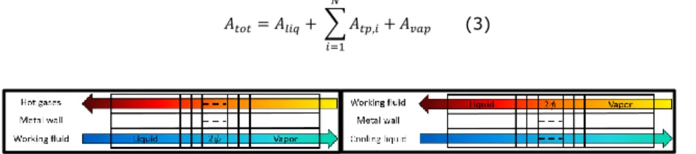
The plate heat exchangers are modeled by means of the Logarithmic Mean Temperature Difference (LMTD) method for counter flow heat exchangers. They are subdivided into three moving-boundaries zones corresponding to the three phases in which the working fluid can be found. In addition, the two-phase region is divided in
N finite volumes. Each of the single-phase zones and each cell of the two-phase
region is characterized by a heat transfer area A and a heat transfer coefficient U whose product is known based on the exchanged power and the LMTD.
𝐴𝑈 = 𝑄̇
𝐿𝑀𝑇𝐷 (1)
The heat transfer coefficient U is calculated by considering two convective and one resistive heat transfer resistances in series (secondary fluid side, metal wall and refrigerant side). 1 𝑈= 1 ℎ𝑤𝑓,𝑐𝑜𝑛𝑣 + 1 𝑘𝑤𝑎𝑙𝑙,𝑐𝑜𝑛𝑑/𝑒𝑤𝑎𝑙𝑙 + 1 ℎ𝑠𝑓,𝑐𝑜𝑛𝑣 (2)
The area of each zone can therefore be computed and the total heat transfer area of the heat exchanger is calculated as follow.
𝐴𝑡𝑜𝑡= 𝐴𝑙𝑖𝑞+ ∑ 𝐴𝑡𝑝,𝑖 𝑁
𝑖=1
+ 𝐴𝑣𝑎𝑝 (3)
Figure 4: Description of the evaporator (left) and condenser (right) models
3.1.1 Single phase heat exchange coefficients and pressure drops
3.1.1.1 Working fluid side
Convective heat transfer coefficients (ℎ𝑐𝑜𝑛𝑣) and Fanning friction coefficients (f) are
evaluated using Martin's correlation (23):
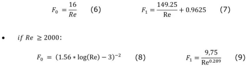
𝑓 = [ (0.045 ∗ tan(𝛽) + 0.09 ∗ sin(𝛽) + 𝐹0 cos(𝛽)) 0.5 + (1 − cos(𝛽) √3.8 ∗ 𝐹1 ) cos(𝛽) ] 2 (4) 𝑁𝑢 = 0.205 ∗ 𝑃𝑟 13∗ (𝑓 ∗ 𝑅𝑒2∗ sin(2 ∗ 𝛽))0.374 (5) with • 𝑖𝑓 𝑅𝑒 < 2000:
𝐹0 = 16 𝑅𝑒 (6) 𝐹1= 149.25 Re + 0.9625 (7) • 𝑖𝑓 𝑅𝑒 ≥ 2000: 𝐹0 = (1.56 ∗ log(Re) − 3)−2 (8) 𝐹1= 9,75 Re0.289 (9)
And where 𝛽 is the chevron angle [rad] per Martin's definition, G is the mass velocity [kg/s.m2], 𝐷ℎ is the hydraulic diameter [m]. The friction pressure drops are computed
with the following relation:
Δ𝑃 =(2 ∗ 𝑓 ∗ 𝐺
2)
𝜌 ∗ 𝐷ℎ
∗ 𝐿 (10)
where 𝜌 is the mean density of the fluid [kg/m³] and L is the plate length [m].
3.1.1.2 Secondary fluid side
For the water-cooled condenser, the Martin's correlation is used as for the working fluid side. It shows good agreements when compared to the experimental data. On the other hand, for the gas heat exchangers (i.e., the evaporators), correlations found in literature lead to large errors on the heat flow rate prediction (up to 50 %). Because the heat transfer resistance is mainly located on the gas side, the heat exchange coefficient must be defined accurately. Thus, measurements were performed on an existing plate type heat exchanger built for an automotive ORC application and a Dittus-Boelter type correlation was derived to evaluate the Nusselt number and the heat exchange coefficient on the gas side (equation 11).
𝑁𝑢 = 𝐶 ∗ 𝑅𝑒𝑚∗ 𝑃𝑟𝑛 (11)
The C and m parameters were calibrated minimizing the error between the measured heat flow rate and the prediction of the model.
Table 2: Parameters of the Nusselt correlation on the gas side (𝑅𝑒 ∈ [104 − 3.8 104])
Parameter Value
C 0.05
m 0.8
n 0.333
3.1.2 Two-phase heat exchanges and pressure drops
Convective heat transfer coefficients (ℎ𝑐𝑜𝑛𝑣) and Fanning friction coefficients (𝑓) are
evaluated using correlation for evaporation and condensation by Han and al. (24,25): • Evaporation 𝐺𝑒1= 2.81 ∗ ( 𝑝𝑐𝑜 𝐷ℎ ) −0.041 ∗ (𝛽)−2.83 (12) 𝐺𝑒 2= 0.746 ∗ ( 𝑝𝑐𝑜 𝐷ℎ ) −0.082 ∗ (𝛽)0.61 (13) (14) (15)
𝐺𝑒3= 64710 ∗ ( 𝑝𝑐𝑜 𝐷ℎ ) −5.27 ∗ (𝛽)−3.03 𝐺𝑒 4= −1.314 ∗ ( 𝑝𝑐𝑜 𝐷ℎ ) −0.62 ∗ (𝛽)−0.47 𝐵𝑜𝑒𝑞= 𝑞 𝐺𝑒𝑞∗ 𝑖𝑓𝑔 (16) 𝑁𝑢 = 𝐺𝑒 1∗ 𝑅𝑒𝑒𝑞 𝐺𝑒2∗ 𝐵𝑜 𝑒𝑞0.3∗ Prl0.4 (17) • Condensation 𝐺𝑒1= 11.2 ∗ ( 𝑝𝑐𝑜 𝐷ℎ ) −2.83 ∗ (𝛽)−4.5 (18) 𝐺𝑒 2= 0.35 ∗ ( 𝑝𝑐𝑜 𝐷ℎ ) −0.23 ∗ (𝛽)1.48 (19) 𝐺𝑒3= 3524.1 ∗ ( 𝑝𝑐𝑜 𝐷ℎ ) −4.17 ∗ (𝛽)−7.75 (20) 𝐺𝑒 4= −1.024 ∗ ( 𝑝𝑐𝑜 𝐷ℎ ) −0.0925 ∗ (𝛽)−1.3 (21) 𝑁𝑢 = 𝐺𝑒1∗ 𝑅𝑒𝑒𝑞 𝐺𝑒2∗ Pr l 1 3 (22)
Where 𝛽 is the chevron angle [rad] according to Martin's definition, 𝑝𝑐𝑜 is the
corrugation pitch [m], 𝐵𝑜𝑒𝑞 is the equivalent boiling number, q is the heat flux [W/m²]
and 𝐺𝑒𝑞 and 𝑅𝑒𝑒𝑞 are the equivalent mass velocity [kg/s.m²] and Reynolds number
defined as a function of the fluid vapor mass fraction x and the densities of the saturated liquid 𝜌𝑙 and vapor 𝜌𝑣:
𝐺𝑒𝑞= 𝐺 ∗ [1 − 𝑥 + 𝑥 ∗ ( 𝜌𝑙 𝜌𝑣 ) 0.5 ] (23) 𝑅𝑒𝑒𝑞= 𝐺𝑒𝑞∗ 𝐷ℎ 𝜇𝑙 (24)
The friction pressure drops are calculated as follow:
𝑓 = 𝐺𝑒3∗ 𝑅𝑒𝑒𝑞
𝐺𝑒4 (25) Δ𝑃 =2 ∗ 𝑓 ∗ 𝐺𝑒𝑞
2
𝜌𝑙∗ 𝐷ℎ
∗ 𝐿 (26)
3.1.3 Sizing of the heat exchangers
For given plate spacing, width, and corrugations (amplitude, chevron angle, and enlargement factor) of the plate heat exchanger, two degrees of freedom are available when sizing the component: the length and the height. These two degrees of freedom are fixed by the heat exchange area requirement and the limitation on the pressure drop on the secondary fluid side.
3.2 Pump model
A model with constant values of global efficiency (equation 27) and volumetric efficiency (equation 28) is proposed for the pump. Based on these efficiencies, the mass flow rate, the outlet temperature, and the mechanical power consumed by the pump can be predicted using the following equations.
𝜖𝑔,𝑝𝑝= 𝑀̇𝑤𝑓,𝑝𝑝∗ (ℎ𝑤𝑓,𝑒𝑥,𝑠,𝑝𝑝− ℎ𝑤𝑓,𝑠𝑢,𝑝𝑝) 𝑊̇𝑝𝑝 (27) 𝜖𝑣,𝑝𝑝= 𝑀̇𝑤𝑓,𝑝𝑝 𝜌𝑤𝑓,𝑠𝑢,𝑝𝑝∗ 𝑁𝑟𝑜𝑡,𝑝𝑝∗ 𝑉𝑠,𝑝𝑝 (28)
For given inlet temperature and pressure conditions, mass flow rate and rotational speed of the pump, the displacement can be computed using equation 28.
3.3 Expander model
A semi-empirical model is proposed to predict the mass flow rate, the outlet temperature and the mechanical power produced by the investigated expanders. This model retains the most important physical phenomena inherent to the expansion machine and involve a limited number of parameters (around 10) which are identified on the basis of performance points. Studies in laboratory showed that these models can predict the performance of the expansion machines with good accuracy. Moreover, their semi-empirical nature enables to extrapolate the performance (26) of the machine for different operating conditions and design characteristics (displacement, sections of the inlet and exhaust ports, etc.). The model used as starting point is the one proposed by Lemort and al. (27) which has been validated for the scroll expander.
Based on the model, the global and volumetric efficiencies of the machine can be evaluated using equations 29 and 30:
3.3.1. Sizing of the expanders
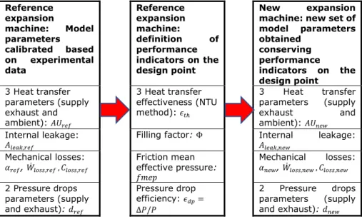
For given inlet temperature and pressure conditions, mass flow rate and rotational speed of the expander, the displacement can be computed using equation 30. As for the heat exchangers on the gas side, experimental data is used as starting point for the sizing of the expansion machines (26,28,29, 30). Indeed, semi-empirical models are used to describe each of the four investigated technologies and the parameters of the models must be defined. It is proposed to first calibrate these parameters using measurements performed on actual machines used as reference. Performance indicators are then defined for each source of losses (Filling factor, friction mean effective pressure, etc.) and are conserved during the design phase of the ORC system. Using these indicators, the corresponding parameters required by the semi-empirical model can be computed for the machine being currently designed.
Table 3: Sizing method used for the expansion machines Reference expansion machine: Model parameters calibrated based on experimental data Reference expansion machine: definition of performance indicators on the design point New expansion machine: new set of model parameters obtained conserving performance indicators on the design point 3 Heat transfer parameters (supply exhaust and ambient): 𝐴𝑈𝑟𝑒𝑓 3 Heat transfer effectiveness (NTU method): 𝜖𝑡ℎ 3 Heat transfer parameters (supply exhaust and ambient): 𝐴𝑈𝑛𝑒𝑤 Internal leakage:
𝐴𝑙𝑒𝑎𝑘,𝑟𝑒𝑓 Filling factor: Φ Internal 𝐴𝑙𝑒𝑎𝑘,𝑛𝑒𝑤 leakage:
Mechanical losses: 𝛼𝑟𝑒𝑓, 𝑊̇𝑙𝑜𝑠𝑠,𝑟𝑒𝑓 , 𝐶𝑙𝑜𝑠𝑠,𝑟𝑒𝑓 Friction mean effective pressure: 𝑓𝑚𝑒𝑝 Mechanical losses: 𝛼𝑛𝑒𝑤, 𝑊̇𝑙𝑜𝑠𝑠,𝑛𝑒𝑤 , 𝐶𝑙𝑜𝑠𝑠,𝑛𝑒𝑤 2 Pressure drops parameters (supply and exhaust): 𝑑𝑟𝑒𝑓 Pressure drop efficiency: 𝜖𝑑𝑝= Δ𝑃/𝑃 2 Pressure drops parameters (supply and exhaust): 𝑑𝑛𝑒𝑤 𝜖𝑔,𝑒𝑥𝑝= 𝑊̇𝑒𝑥𝑝 𝑀̇𝑤𝑓,𝑒𝑥𝑝∗ (ℎ𝑤𝑓,𝑠𝑢,𝑒𝑥𝑝− ℎ𝑤𝑓,𝑒𝑥,𝑠,𝑒𝑥𝑝) (29) 𝜖𝑣,𝑒𝑥𝑝= 𝑀̇𝑤𝑓,𝑒𝑥𝑝 𝜌𝑤𝑓,𝑠𝑢,𝑒𝑥𝑝∗ 𝑁𝑟𝑜𝑡,𝑒𝑥𝑝∗ 𝑉𝑠,𝑒𝑥𝑝 (30)
3.4 System model
The global model of the system is obtained by interconnecting each component model. The two main assumptions for the evaluation of the performance in design and off-design are the following:
• The sub-cooling degree at the outlet of the condenser is 5K. • The fixed global efficiency of the pump is 50%.
4. SELECTION OF THE DESIGN CONDITIONS
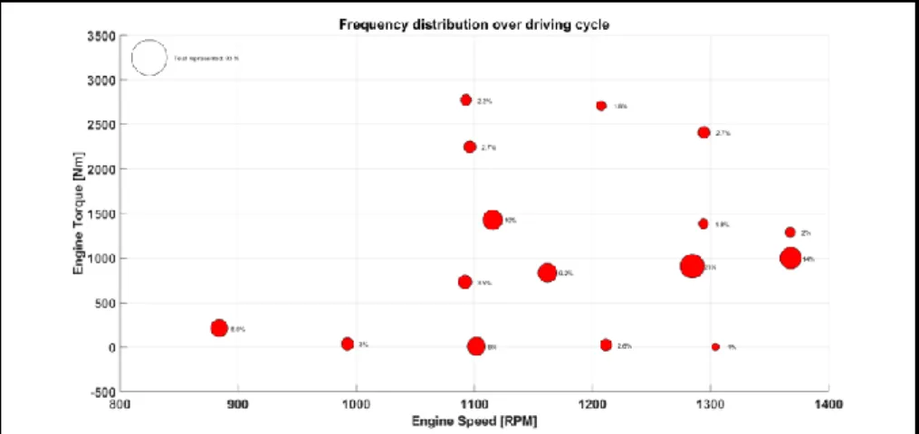
The first step of the design process is the selection of the design conditions. To achieve this, the frequency distribution of the couples (engine torque, engine speed) over the driving cycle is mapped. 5 torque levels and 6 speed levels are considered in this study, which leads to 17 operating points. For each of these points, a system model including a simplified version of the expansion machine (including only losses due to the non-adapted volume ratio) are designed and optimized. The superheating degree and the built-in volume ratio of the expander are fixed and the evaporating pressure and the pinch-point of the heat exchangers of the 6 topologies are optimized for the 3 working fluids so to maximize the power produced. The mass of the heat exchangers is constrained to a limit of 60 kg while the pressure is limited to a maximum of 32 bar based on the information coming from a truck manufacturer. Then the power produced by each topology is maximized in off-design for the other 16 operating points, still optimizing the evaporating pressure. Finally, for each of the 17 systems designed, an average is performed on the power produced and weighted over the 17 points using the frequency distribution so to identify the most promising design conditions for each topology and each fluid. At the end, the point corresponding to the most important fuel consumption is leading to the maximal weighted average power and is selected for the design phase.
Figure 5: Frequency distribution of the couples (engine torque, engine speed) over the driving cycle
5. DESIGN: THERMO-ECONOMIC OPTIMIZATION
The design points being defined, the 24 systems including the detailed models of the 4 expansion machine technologies can be designed using the 3 working fluids (72 simulations models).
5.1 Costs
The objective of the design optimization is the minimization of the specific investment cost (SIC), ratio between the Total Investment Cost (TIC) and the power produced by the system. The TIC is the sum of the direct cost (DC) and Indirect Costs (IC). In the DC can be found the cost of the system components (𝐶𝑠𝑦𝑠𝑡), of the fluid (𝐶𝑤𝑓), of
the piping (𝐶𝑝𝑖𝑝𝑖𝑛𝑔) and of the instrumentation and control of the system (𝐶𝑖𝑛𝑠𝑡𝑟,𝑐𝑡𝑟𝑙).
The IC are mainly composed of the engineering (𝐶𝑒𝑛𝑔) and contingency costs (𝐶𝑐𝑜𝑛𝑡).
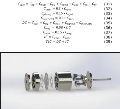
Except for the cost of the system, assumptions are achieved on the DC and the IC. They are described in equation 31 to 39. The cost of the system is calculated based on an estimation of the cost of the components made from experience and discussion with manufacturers. These costs are listed in table 3. The costs of the expansion machine technologies are estimated using Solidworks. 3D sketches (Figure 8) were performed, or were directly used when available, to establish the list of the main parts of the machines and evaluate their cost as a function of the displacement of the expander assuming the material (stainless steel) and the fabrication process (molding) and a serial production of 20.000 machines per year.
𝐶𝑠𝑦𝑠𝑡= 𝐶𝑝𝑝+ 𝐶𝐸𝐺𝑅+ 𝐶𝐸𝐺+ 𝐶𝐸𝐺𝑅2+ 𝐶𝑒𝑥𝑝+ 𝐶𝑐𝑑+ 𝐶𝐿𝑇 (31) 𝐶𝑖𝑛𝑠𝑡𝑙= 0.3 ∗ 𝐶𝑠𝑦𝑠𝑡 (32) 𝐶𝑝𝑖𝑝𝑖𝑛𝑔= 0.15 ∗ 𝐶𝑠𝑦𝑠𝑡 (33) 𝐶𝑖𝑛𝑠𝑡𝑟,𝑐𝑡𝑟𝑙= 0.2 ∗ 𝐶𝑠𝑦𝑠𝑡 (34) 𝐷𝐶 = 𝐶𝑠𝑦𝑠𝑡+ 𝐶𝑤𝑓+ 𝐶𝑖𝑛𝑠𝑡𝑙+ 𝐶𝑝𝑖𝑝𝑖𝑛𝑔+ 𝐶𝑖𝑛𝑠𝑡𝑟,𝑐𝑡𝑟𝑙 (35) 𝐶𝑒𝑛𝑔= 0.08 ∗ 𝐷𝐶 (36) 𝐶𝑐𝑜𝑛𝑡= 0.15 ∗ 𝐶𝑒𝑛𝑔 (37) 𝐼𝐶 = 𝐶𝑒𝑛𝑔+ 𝐶𝑐𝑜𝑛𝑡 (38) 𝑇𝐼𝐶 = 𝐷𝐶 + 𝐼𝐶 (39)
Figure 6: Example of 3D sketches used to estimate the cost of the expanders
Table 4: Cost of the ORC components
Component Variable Cost [€]
Heat exchanger Mass (kg) 250 + 5 ∗ 𝑀𝑎𝑠𝑠
Expander Displacement (cm³) Scroll Screw Piston Vane 15.94 ∗ 𝑉𝑠,𝑐𝑝0.667 47.739 ∗ 𝑉𝑠,𝑐𝑝0.4167 14.223 ∗ 𝑉𝑠,𝑐𝑝0.6582 11.111 ∗ 𝑉𝑠,𝑐𝑝0.8716
Low temperature circuit / 200
Working fluid Mass (kg)
R245fa Ethanol Water 25 ∗ 𝑀𝑎𝑠𝑠 1.096 ∗ 𝑀𝑎𝑠𝑠 0.124 ∗ 𝑀𝑎𝑠𝑠
5.2 Constraints and optimization variables
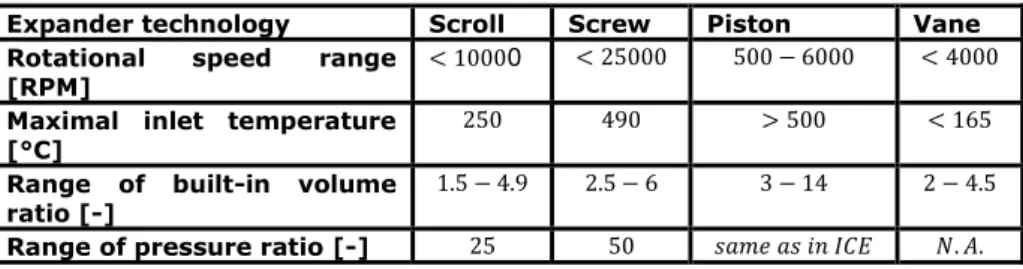
When selecting the design conditions, a simplified model of the expansion machine is used. The constraints of the optimization are also reduced. When considering the actual system, additional constraints should be considered. The rotational speed, the inlet temperature, the vapor mass fraction, and the pressure ratio are generally limited for each expansion machine technology. These validity ranges are summarized in Table 4 resulting from a literature review. On the other hand, the temperature of the exhaust gases at the outlet of the evaporator must be kept above a minimal value (around 100°C) to avoid the condensation of acids. The NOx reduction strategy should not be impacted by the WHR system and the recirculated gases should be kept below a maximal temperature (around 120°C). These constraints as well as the optimization variables during the design are summarized in Table 5.
Table 5: State of the art performed for the expansion machine technologies Expander technology Scroll Screw Piston Vane Rotational speed range
[RPM]
< 10000 < 25000 500 − 6000 < 4000
Maximal inlet temperature [°C]
250 490 > 500 < 165
Range of built-in volume ratio [-]
1.5 − 4.9 2.5 − 6 3 − 14 2 − 4.5
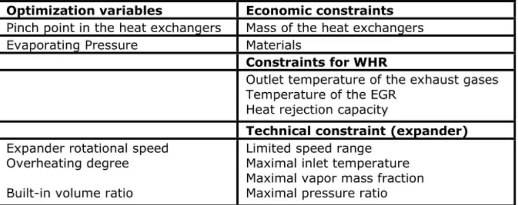
Table 6: Constraints and variables of the thermo-economic optimization Optimization variables Economic constraints
Pinch point in the heat exchangers Mass of the heat exchangers Evaporating Pressure Materials
Constraints for WHR
Outlet temperature of the exhaust gases Temperature of the EGR
Heat rejection capacity
Technical constraint (expander)
Expander rotational speed Overheating degree Built-in volume ratio
Limited speed range Maximal inlet temperature Maximal vapor mass fraction Maximal pressure ratio
5.3 Results
This study does not have the pretention to give the exact figures of what would be the performance of the waste heat recovery system installed on a truck but rather to give a methodology and the trends. This is a prediction work which is obviously limited by the assumptions made. Being more accurate would require more complex and deterministic models of the ORC components (CFD). However, it would also lead to unacceptable calculation times at this stage because of the number of topologies to investigate and the number of optimizations to perform. Here a good compromise between accuracy and calculation time is expected because of the use of validated but still relatively simple semi-empirical models (0D).
The active-set algorithm through the Matlab optimization toolbox is used to performed a global minimization of the SIC of each system. Results are shown in Figure 9. It can be observed that topologies 2 to 5, including the EGR as heat source are the most promising whatever the working fluid. The topology with the split of the EGR heat exchanger is on the other hand more expensive while the power produced by the systems is limited when using the exhaust gases only. In general, ethanol seems to be the most appropriate working fluid. Also, because of the low temperature of the heat source, water should be avoided using topology 1. Moreover, water is not well adapted to the vane expander. This is explained by the constraint on the maximal inlet temperature with this technology. The high built-in volume ratio of the piston expander makes it not suitable to be used with R245fa. Finally, the most appropriate solution, based on the assumptions made here is the use of the screw expander integrated in the parallel topology and using ethanol as working fluid.
Figure 7: SIC of the 4 expansion machines, 6 topologies and 3 working fluids
6. OFF DESIGN PERFORMANCE: OPTIMIZATION
Finally, the performance of the 4 most promising architectures (2 to 5) and using ethanol as working fluid are maximized optimizing the evaporating pressure and the superheating degree for each of the 16 off-design operating points of the frequency distribution map (Figure 7). A weighted average based on these frequencies is performed on the power produced by the systems. Results are shown in Figure 10. Again, the parallel architecture using the screw expander seems to be the most appropriate solution for the WHR system. However, results are close between the scroll, the screw and the piston expander and performance and cost cannot be the only selection criteria at the end. Thus, for instance, the parallel architecture will lead to a more complex control strategy since two mass flow rates must then be regulated and specially the flow cooling the recirculated gases.
Figure 8: Off-design performance of the most promising topologies: Average power produced by the systems and weighted based on the
frequency distribution of the engine operating points
7. CONCLUSION AND PERSPECTIVE
In conclusion, a 3-steps optimization methodology has been proposed for the selection of the heat sources, working fluid and expansion machine of an ORC recovering the heat wasted from the engine of a heavy-duty truck. 6 topologies, 3 working fluids and 4 expansion machines technologies are considered. First an optimization is performed to select the design condition. Then a thermo-economic optimization is achieved to design the systems. Finally, the performance is maximized in off-design. Based on the results, it is shown that ethanol is the most appropriate working fluid and the use of the screw expander leads to the best average performance. However, results are close between the scroll, the screw, and the piston expanders. Quasi-static simulations could be performed along driving cycles of the truck to evaluate the energy recovered by the systems and thus the fuel consumption reduction. To be more accurate, this would also require evaluating the power consumption of the fan when it is engaged. Finally, criteria other than performance and cost should be considered (complexity of the system and of the control strategy, safety, etc.).
REFERENCES
1. Kokic P, Crimp S, Howden M, A probabilistic analysis of human influence on recent record global mean temperature changes, Climate Risk Management 2014;3:1-12.
2. IEA, Key world energy statistics, http://www.iea.org/publications/ freepublications//publication/KeyWorld2014.pdf 2014.
3. UNFCCC, Kyoto protocol to the united nations framework convention on climate change, http://unfccc.int/resource/docs/convkp/kpeng.html, 1992.
4. European comission, Towards a strategy to address co2 emissions from HDV., http://ec.europa.eu/clima/policies/transport/vehicles/heavy/index.htm, 2013.
5. European comission, Climate action, http://europa.eu/pol/pdf/ipbook/fr/climate_action_fr.pdf.
6. Badr O, Probert SD, O Callaghan PW, Selecting a working fluid for a Rankine cycle engine, Applied Energy 1985;21:1-42.
7. Bao J, Zhao L, A review of working fluid and expander selections for organic rankine cycle, Renewable and Sustainable Energy Reviews 2013;24:325-342. 8. Latz G, Andersson S, Munch K, Selecting an expansion machine for vehicle
waste-heat recovery systems based on the rankine cycle, SAE Technical Paper 2013-01-0552, 2013, doi:10.4271/2013-01-0552.
9. Quoilin S, Van Den Broek M, Declaye S, Dewallef P, Lemort V, Techno-economic survey of organic rankine cycle (orc) systems, Renewable and Sustainable Energy Reviews 2013;22:168-186.
10. Shu G, Liu L, Tian H, Wei H, Yu G, Parametric and working fluid analysis of a dual-loop organic rankine cycle (dorc) used in engine waste heat recovery, Applied Energy 2014;113:1188-1198.
11. Toffolo A, Lazzaretto A, Manente G, Paci M, A multi-criteria approach for the optimal selection of working fluid and design parameters in organic Rankine cycle systems, Applied Energy 2014;121:219-232.
12. Grelet V., Rankine cycle based waste heat recovery system applied to heavy duty vehicles: topological optimization and model based control, PhD Thesis, 2016. 13. Teng, H., Regner, G., and Cowland, C. Waste heat recovery of heavy-duty diesel
engines by organic Rankine cycle part i: Hybrid energy system of diesel and rankine engines. SAE Technical Paper, 2007. SAE International.
14. Edwards, S., Eitel, J., Pantow, E., Geskes, P., Lutz, R., and Tepas, J. Waste heat recovery: The next challenge for commercial vehicle thermomanagement, 2012. SAE International Journal of Commercial Vehicles, 5:395–406.
15. NoWaste Project, http://nowasteproject.eu
16. Quoilin S, Sustainable energy conversion through the use of organic Rankine cycles for waste heat recovery and solar applications., Ph.D. thesis, University of Liege, Liege, Belgium, 2011.
17. Amicabile S. Lee J., KUM D., A comprehensive design methodology of organic Rankine cycles for the waste heat recovery of automotive heavy-duty diesel engines, Applied Thermal Engineering 87 (2015) 574e585.
18. Grelet V., Dufour P., Nadri M., Reiche T., Lemort V., Modeling and control of Rankine based waste heat recovery systems for heavy duty, IFAC-PapersOnLine 48-8 (2015) 568–573.
19. Grelet V., Reiche T., Lemort V. Nadri M., Dufour P., Transient performance evaluation of waste heat recovery Rankine cycle based system for heavy duty trucks, Applied Energy 165 (2016) 878–892.
20. Maciann V, Serrano JR, Dolz V, Sanchez J, Methodology to design a bottoming Rankine cycle, as a waste energy recovering system in vehicles. Study in a HDD engine, Applied Energy 2013;104:758-771.
21. T. Yamaguchi, Y. Aoyagi, N. Uchida, A. Fukunaga, M. Kobayashi, T. Adachi, et al. Fundamental study of waste heat recovery in the high boosted 6-cylinder heavy duty diesel engine SAE Int J Mater Manuf, 8 (2) (2015), pp. 209–226 http://dx.doi.org/10.4271/2015-01-0326
22. Zheng N, Zhao L, Wang XD, Tan YT, Experimental verication of a rolling-piston expander that applied for low-temperature organic rankine 485 cycle, Applied Energy 2012;112:1265-1274.
23. Martin H, A theoretical approach to predict the performance of chevron-type plate heat exchangers, Chemical Engineering and Processing 35 1996;301-310.
24. Han DH, Lee KJ, Kim YH, Experiments on the characteristics of evaporation of R410a in brazed plate heat exchangers with different geometric configurations, Applied Thermal Engineering 2003;23;1209-1225.
25. Han DH, Lee KJ, Kim YH, The characteristics of condensation in brazed plate heat exchangers with different chevron angles, Journal of the Korean Physical Society 2003;43,1;66-73.
26. Dickes R. Dumont O., Daccord R., Quoilin S., Lemort V., Modelling of organic Rankine cycle power systems in off-design conditions: An experimentally-validated comparative study., Energy 2017, In Press, Accepted Manuscript, Available online 30 January 2017.
27. Lemort V, Quoilin S, Cuevas C, Lebrun J,, Testing and modeling a scroll expander integrated into an organic rankine cycle, Applied Thermal Engineering 2009; 29; 3094-3102.
28. Oudkerk JF., Development of a semi-analytical model of volumetric expander for system-level simulation 2016, in Proceedings of ECOS 2016.
29. Vodicka V., Guillaume L., Mascuch J., Lemort V., Testing and modeling a vane expander used in an orc working with hexamethyldisiloxane (MM) 2015, in proceedings of ASME ORC 2015.
30. Dumont O., Experimental investigation of four volumetric expanders, article in preparation, IV International Seminar on ORC Power Systems, ORC2017 13-15 September 2017, Milano, Italy