1
Thermal rectifier efficiency of various bulk-nanoporous silicon devices
H. Machrafi1,2, G. Lebon1,D. Jou3,*,
1Thermodynamique des Phénomènes Irréversibles, Université de Liège, 4000 Liège, Belgium
2Service Chimie-Physique, Université Libre de Bruxelles, 1050 Brussels, Belgium
3Departament de Física, Universitat Autònoma de Barcelona, 08193 Bellaterra, Catalonia, Spain
Abstract
Our objective is to calculate and to compare the rectifying thermal coefficient of various bulk-porous silicon configurations. We consider successively homogeneous devices involving two- and three elements and several graded devices characterized by variable porosity and/or size of the pores along the system. The criterion is to obtain rectifying coefficients different from one in order that thermal rectification be as efficient as possible. In that respect, it turns out that the porous-bulk-porous configurations are of little interest, in contrast to the bulk-porous-bulk systems whose rectifying coefficients may be larger than two and comparable to the values of the simpler two-element bulk-porous devices. Graded systems with either a variable porosity or a variable pore size do not exhibit better results. However, when both porosity and pore size are varying along the device, the highest efficiency is obtained.
Keywords: thermal rectifiers, phononics, bulk-nanoporous silicon, homogeneous and non-homogeneous systems.
Email: [email protected] (corresponding author) Nomenclature
ap pore size
C specific heat k heat conductivity Kn Knudsen number L length of the element q heat flux
R rectifying coefficient Rth thermal boundary resistance
T temperature
2 x longitudinal coordinate
Greek symbols
porosity Λ mean free path
Subscripts
d direct direction F interface G interface H hot
i=1,2,3 element under study
L low max maximum min minimum r reverse direction 0 reference value Superscripts eff effective 0 bulk 1 Introduction
Thermal rectifiers have attracted an increased interest not only in fundamental but also in applied research, [1-6] presently framed within the relatively new topic of phononics [7-9]. The concept of thermal rectification can be traced back to Starr in 1936 [10]. By analogy with electronic diodes used for the control of electric current, thermal rectifiers are devices allowing heat to flow easily in one direction but offering strong resistance in the reverse direction. Search for suitable materials and configurations enhancing heat rectification has been intensely activated principally during the two last decades [11-14]. Among the current and widely used techniques, let us mention these based on adsorption/desorption properties [15], phase change [16], photon radiation [17] and thermal expansion-contraction [6] heat transfer between materials with different temperature–dependent heat conductivities [18, 19], the main objective is the search for thermal diodes with the highest performance. The subject opens the way to
3
specific applications, especially in the field of energy-saving structures, solar energy conversion, nano-electronic cooling, aero-spatial industry and cryogenics.
In the present theoretical approach, we consider successively discontinuous devices constituted by the junction of bulk and nanoporous Si and porous non-homogenous Si. The purpose of this work is the search of suitable material configurations leading to the most efficient heat rectification. Although the actual analysis is limited to silicon there will be no difficulty to extend it to other materials.
The underlying property responsible for heat rectification is the behavior of the heat conductivity of nanoporous materials [1,20]. When the dimensions of the pores are comparable or smaller than the mean free path of the phonons, the effective heat conductivity of the porous material is generally much lower than that of the corresponding bulk crystal.
Thermal rectification in Si devices has been recently analyzed theoretically by Criado-Sancho et al. [2]. These authors base their approach on an expression of Fourier’s law using for the effective heat conductivity an expression derived in the framework of phonon hydrodynamics. Our aim is to complement and compare with Criado-Sancho et al. results, proposing novel configurations with better results. The present analysis uses instead for the heat conductivity a relation proposed by Sumirat et al. [21], which emphasizes more particularly the effect of phonon scattering by pores. The Sumirat model has been validated with results derived by Machrafi and Lebon [22] in the framework of extended irreversible thermodynamics [23], it is mathematically simpler than the hydrodynamic model used by Criado et al. and allows for a more exhaustive exploration of several aspects of the problem.
In this paper, we investigate which configuration among several bulk-nanoporous lattices will yield the most efficient rectification. We will examine successively several different devices consisting of juxtaposed homogeneous bulk and nanoporous Si samples and will end with non-homogeneous porous materials wherein both porosity and particles’ size are varying in space. The important quantity characterizing rectification is the thermal rectifying coefficient 𝑅 (also called diodicity by some researchers) defined by the ratio of the heat flows in the direct and reverse directions:
𝑅 ≡ |𝑞 |/|𝑞 | (1)
with 𝑞 the heat current in the direct “conducting” direction and 𝑞 in the reverse “insulating” one. To get an amplification effect, one must have 𝑅 ≠ 1; when |𝑞 | is larger than |𝑞 | (which is the situation investigated in the present work), one has 𝑅 > 1. Of course, if the conducting and insulating directions would be switched, one should have 𝑅 < 1. In two phase situations involving bulk and porous Si samples it was found [1] that 𝑅 is of the order of 1.5, it is also noted that the effect of porosity on heat conduction is particularly relevant at low temperatures not exceeding 200 K. Similar values for R were obtained with two polycrystalline cobalt oxides segments [19], more recently, a solid state structure with shape memory alloys was built by Tso et al. [4] who recorded an 𝑅-value of about 90.
The mechanism underlying thermal rectification has also been interpreted as a consequence of a negative differential thermal resistance defined as 𝑅 = (𝜕𝑞/𝜕𝑇 ) and an equivalent definition for 𝑅 obtained by permuting the different indices 𝐻 and 𝐿. Classically, the heat flow increases with increasing thermal gradients and therefore both 𝑅 and 𝑅 are positive so that by defining 𝑅 as 𝑅 = |𝑅 |/(|𝑅 | + |𝑅 |), it is found that 𝑅 < 1 and the device will not work as a rectifier for which it is imperative that either 𝑅 or 𝑅 be negative. In the following, we will not follow this route. Instead, we will focus on the definition (1) of diodicity. This choice is not unique, though. For instance, some authors (e.g. [4, 18]) use the following quantities to define the level of rectification, either
4 𝑅∗ = | | | | | | | |= (2) or 𝑅∗∗ = | | | | | | = 𝑅 − 1 (3)
By selecting one or another of these definitions, one obtains values of the diodicity that may differ from several orders of magnitude as illustrated in section 4.
The paper will run as follows. In section 2, the effect of porosity on the effective thermal conductivity of nanoporous materials, illustrated by nanoporous Si, is discussed. In section 3, thermal rectifiers consisting of homogeneous bulk-porous Si configurations are considered: two-phase bulk-porous Si and three-phase devices, namely bulk-bulk Si and porous-bulk-porous Si systems, are successively examined. In section 4, graded nanoporous Si systems, with the porosity and/or pore size varying gradually along the sample, are investigated. Conclusions are drawn in Section 5.
2 Thermal conductivity of bulk and porous silicon
The expression of the thermal conductivity of porous materials is a central quantity in the determination of the rectifying coefficient (see for instance [24] for a review). In the present analysis, we use for the effective thermal conductivity of porous Si the analytical approximate result derived by Sumirat et al. [11] on the bases of the kinetic theory of phonons in solids, namely
𝑘 (𝜑, 𝑇, 𝐾𝑛) = 𝑘 (𝑇) ( )
( ). (4)
This formula will be used as a mathematically simple efficient tool in order to perform our investigation. The quantity 𝑘 (𝑇) is the bulk thermal conductivity, which depends generally on the temperature 𝑇. For Si, it is of the order 3700 Wm-1K-1 at 40 K, 2200 Wm-1K-1 at 58 K, 1350 Wm-1K-1 at 79 K, 800 Wm-1K-1 at 105 K, 560 Wm-1K-1 at 127 K, and 475 Wm-1K-1 at 153 K [10]. The behaviour of the silicon bulk thermal conductivity versus the temperature in the range 40 – 150 K is given by the solid black line of Fig. 1. In relation (2), 𝜑 designates the porosity, i.e. the ratio of the volume occupied by the pores and the total volume, 𝐾𝑛 is the Knudsen number defined by 𝐾𝑛(𝑇) ≡ Λ(𝑇)/𝑎 , with 𝑎 the pore radius and Λ(𝑇) the temperature-dependent mean free path of the phonons. The mean free path is calculated from the classical expression of the thermal conductivity derived from Debye’s model, namely 𝑘(𝑇) =
𝐶(𝑇)𝑣Λ(T). From the experimental values of the thermal conductivity 𝑘(𝑇) (e.g.[25]), the knowledge of the specific heat 𝐶(𝑇) [25] and the assumption that the phonon group velocity 𝑣 is temperature independent [25-27], one obtains directly the value of the mean free path Λ(T). It is equal to 6680 nm at 50 K, 1430 nm at 80 K, 700 nm at 100 K, 340 nm at 130 K, and 180 nm at 150 K. For large Knudsen numbers (i.e. when the phonon mean free path is much longer than the radius of the pores), the heat transfer is mainly described by ballistic contributions of phonon collisions against pores. For low Knudsen numbers, the diffusive regime is dominant. Making an interpolation of the mean free path as a function of the temperature, we can plot from Sumirat’s expression (1) the effective thermal conductivity of the nanoporous medium as a function of the temperature for several pore radii (see Fig. 1). In [21], the dependence of
5
𝑘 on the temperature is not made explicit as only the dependence on the porosity is investigated. However, it is clear from the above discussion that expression (1) is strongly temperature-dependent.
Fig. 1.Thermal conductivity versus temperature for bulk (𝑘 (𝑇)) and nanoporous Si (Eq. (2)):
porosity 𝜑 = 0.1 and pore sizes 𝑎 are varying from 1000 to 5 nm.
It is seen that the conductivities exhibit opposite trends as a function of the temperature: in the case of bulk Si, it is decreasing, while for porous systems, it is increasing; note however that at relatively large pores sizes (𝑎 > 100 m), it is decreasing after reaching a maximum. This property is the key for obtaining thermal rectification. Since the bulk phonon mean free path is relatively large and strongly temperature-dependent at low temperatures, the contributions of the pores become especially relevant. As the phonon mean free path increases when temperature is lowered, the increase of the denominator of relation (2) will be partially compensated by the increase of the numerator, whence the occurrence of a maximum. At higher temperatures, around 140 K, the contribution of the temperature effect on the mean free path of the phonons becomes less important and, at large pores (𝑎 > 500 m), the conductivity of nanoporous Si is close to that of the bulk one. This is understandable since at larger pore sizes, the ballistic contribution becomes negligible with respect to the diffusive one (𝐾𝑛 ≪ 1) and Fourier’s heat transfer is dominating. The effect of the porosity on the thermal conductivity is not to be investigated further, since it has been thoroughly studied in a previous work [22]. It is generally admitted that porosity reduces the thermal conductivity. As for the pore sizes, its role is also experimentally well known. For instance, in [28, 29] it is observed that at room temperature, for a porosity 𝜑 = 0.4, the effective thermal conductivity of porous Si is 31.2 Wm−1K−1 for 𝑎
= 100 nm [28] and 1.2 Wm−1K−1 for 𝑎 = 5 nm [29]. These results are much lower than the
heat conductivity of bulk Si which is 148 Wm−1K−1 under the same temperature conditions. We
will no longer comment about the parametric dependence of the thermal conductivity as the purpose of this work is rather to investigate the performances of the coupled bulk-nanoporous materials from the point of view of thermal rectification. We choose therefore in the forthcoming one single value for the porosity, say 𝜑 = 0.1, and one pore size, say 𝑎 = 150 nm.
3 Homogeneous two- and three-phase systems 3.1 Bulk-porous Si configurations 40 60 80 100 120 140 T K 1 10 100 1000 k W m 1K 1 ap 5 nm ap 50 nm ap 150 nm ap 500 nm ap 1000 nm Bulk silicon
6
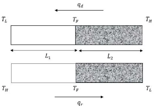
The simplest configuration is that represented by Fig. 2, consisting of a two-homogeneous
phase system: bulk Si of length L in series with nanoporous Si with length L with the hot face
respectively at the porous and the bulk side. The first situation is referred to as the direct direction (with heat flux 𝑞 ) and the second one as the reverse one (with heat flux 𝑞 ). The rectifying effect is shown through the difference of values of the direct (𝑞 ) and the reverse (𝑞 ) values of the heat flux.
Fig. 2. Schematic picture of the thermal transistor: (a) direct heat flow, (b) reverse heat flow. Bulk material is represented by a virgin surface and the porous phase by a shaded one. The temperatures at the ends of the device are 𝑇 (high) and 𝑇 (low), respectively, while at the interface bulk-porous the temperature is 𝑇 . The lengths of crystalline and porous Si are 𝐿 and 𝐿 , respectively.
We assume that the assembly is made out of two homogeneous materials taking the form of rods or cylinders of constant cross section, wide enough in comparison with the value of the bulk phonon mean free path, in order that the collisions with the walls do not contribute to the thermal conductivity.
In principle, interfacial effects between bulk and nanoporous Si are expected. A way to account for them is to evaluate the dimensionless coefficient α [30, 31] defined by
0 th R k L (5)
wherein Rth is a measure of the thermal boundary resistance, 𝑘 the bulk heat conductivity and L a reference length, say the mean length of the segments. The product 𝑅𝑘 = 𝛼 is the so-called Kapitza length. Values of α<<1 mean weak interfacial effects. If Rth=0, one has α =0 and the interface is said to be perfect. Generally, R is non-zero and given by [31]
7
𝑅 = 4/𝐶 𝑣 + 4/𝐶 𝑣 , (6)
for diffuse phonon’s scattering, with 𝐶 and 𝑣 (𝑖 = 𝑏, 𝑝) standing for the volumetric specific heat and phonon group velocity and indices 𝑏 and 𝑝 refer to the bulk and porous segments of the device, respectively. To give an idea of the order of magnitude of the coefficient α, we have calculated it at an intermediate temperature T =100 K. At this value, the specific heats of Si and air (supposed to fill the pores) are known to be 0.6*106 J/m3K and 2.9*103J/m3K, respectively. The velocity of phonons at 100K in air is about 200 m/s and that of silicon is equal to 6400 m/s. The latter result is derived from Debye’s model, 𝑘 = 𝐶𝑣Λ, with 𝑘 = 900 Wm-1K- 1 as obtained from Fig. 1. The corresponding values in the porous segment are obtained from the volumetric average of the silicon and air data [22]. Making use of these numerical values, it is found that the thermal boundary resistance coefficient and the Kapitza length are given by R=2.2*10-9 m2K/W and 𝛼 ≈ 2 ∗ 10 m. The latter result is significant as it justifies that the effect of interfacial thermal boundary resistance can be neglected for device lengths L longer
than 2 µm, which represents a reasonable value within the context of the present work.
Thermal boundary resistance may become dominant when the number of device layers is increased as in superlattice structures. In principle, the role of a thermal boundary resistance could be explicitly studied by introducing between the bulk and porous segments a third one undergoing a temperature drop, in analogy with the analysis presented in Section 3.2.
Let us go on with the calculation of the heat transport in the device schematized by Fig.2. The hot head of the device is kept at 𝑇 = 150 K, and the cold side 𝑇 varies from 40 to 150 K. The heat flow in each element is governed by Fourier’s law
𝑞 = −𝑘 (𝑇, 𝜑, 𝐾𝑛)(𝑑𝑇/𝑑𝑥), (7)
wherein 𝑘 is given by expression (4) in the case of the nanoporous element and by 𝑘 (𝑇)
for the bulk segment. The hypothesis of stationarity implies that the heat flux remains uniform throughout the sample, its expressions in the direct and reverse directions reads respectively as [18-20]
𝑞 ≡ − ∫ 𝑑𝑇 = − ∫ 𝑑𝑇, (8)
𝑞 ≡ − ∫ 𝑑𝑇 = − ∫ 𝑑𝑇. (9)
Equalizing the second and third terms of equations (8) and (9) respectively leads to an algebraic relation of the form 𝑓(𝐿 /𝐿 , 𝑇 , 𝑇 , 𝑇 ) = 0, allowing to determine the intermediate
temperature 𝑇 in terms of 𝐿 /𝐿 , 𝑇 and 𝑇 . After the temperature junction 𝑇 is known, the
heat fluxes 𝑞 and 𝑞 can be calculated and finally the value of 𝑅 = |𝑞 |/|𝑞 | can be determined. In Fig. 3 are plotted the values of R as a function of 𝑇 for several values of 𝐿 /𝐿 and with fixed values of 𝜑 (= 0.1) and 𝑎 (=150 nm).
8
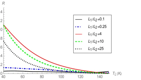
Fig. 3. Rectifying coefficient 𝑅 as a function of 𝑇 for several values of the ratio 𝐿 /𝐿 for the device in Fig. 2, 𝜑 = 0.1, 𝑎 = 150 nm and 𝑇 = 150 K.
Several comments are in form. First, Fig. 3 shows that 𝑅 > 1, for all the 𝐿 /𝐿 ratios considered in this work. This can be understood by recalling that the porous region is characterized by the largest thermal resistance, so that a higher temperature (𝑇 in the direct case) at the porous side will contribute to a larger heat flow than by prescribing a lower temperature (𝑇 in the reverse case).
Second, by increasing the 𝐿 /𝐿 -ratio from 0.1, the rectifying coefficient increases gradually and attains a maximum value at = 4 but afterwards, it decreases with larger 𝐿 /𝐿 values. This can be interpreted as follows. For 𝐿 ≫ 𝐿 , the porous region of dimension 𝐿 is so tiny that it will not contribute to the heat flux, and things happen as there were only one single region, the direction of the heat flux is of slight influence and the rectifying coefficient tends to unity. By increasing 𝐿 , we have again a two-phase situation; the heat flux in the direct case becomes larger and larger, so that an increase of 𝐿 is tantamount to an increase of the rectifying coefficient. Finally, for 𝐿 ≫ 𝐿 , we recover a quasi-one-phase situation with R decreasing once more to unity. It is therefore not surprising to observe an extremum value of R at intermediate values of 𝐿 and 𝐿 .
3.2 Bulk-porous-bulk and porous-bulk-porous Si configurations
We perform the same study as in the previous subsection, but with systems composed out of three elements: porous-bulk-porous on one side (Fig. 4) and bulk-porous-bulk on the other side (Fig. 5). Since, we already have considered the influence of the -ratio, we will select = 4, which corresponds to the largest rectifying coefficient found in the previous subsection and express 𝑅 as a function of 𝑇 for various values of the aspect ratio 𝐿 /𝐿 of the external elements. 40 60 80 100 120 140 TL K 1.0 1.2 1.4 1.6 1.8 2.0 2.2 2.4 R L1L2 25 L1L2 10 L1L2 4 L1L2 0.25 L1L2 0.1
9
Fig. 4. The device is composed of three homogeneous regions of porous Si (left side), bulk Si (middle side) and porous Si (right side). The system is subject to a temperature difference ∆𝑇 =
𝑇 (high) − 𝑇 (low) at its boundaries. 𝑇 and 𝑇 denote temperatures at the interfaces. The
porous elements of lengths 𝐿 and 𝐿 are characterized by the same porosity.
Fig. 5. The device is composed of three regions of bulk Si (left side), porous Si (middle side) and bulk Si (right side).
The heat fluxes for the porous-bulk-porous device are given by
𝑞 ≡ − ∫ 𝑑𝑇 = − ∫ 𝑑𝑇 = − ∫ 𝑑𝑇, (9)
10
and for the bulk-porous-bulk device,
𝑞 ≡ − ∫ 𝑑𝑇 = − ∫ 𝑑𝑇 = − ∫ 𝑑𝑇, (11)
𝑞 ≡ − ∫ 𝑑𝑇 = − ∫ 𝑑𝑇 = − ∫ 𝑑𝑇. (12)
To determine the values of the intermediate temperatures 𝑇 and 𝑇 , for a fixed 𝑇 and a varying 𝑇 , we equalize on one side the second and third terms of (11) and (12) and the second and fourth terms on the other side. After calculating the direct and reverse heat fluxes, one obtains directly the corresponding rectifying coefficient. In the case of the porous-bulk-porous configuration, the rectifying coefficient remains close to unity for a large range of the -ratio, meaning that this kind of device is not suitable for thermal rectification. This can be understood by noticing that in this configuration, we have two porous media with a relatively large thermal resistance. So, the thermal properties of the bulk phase in between them will not undergo much modifications, whether one porous phase is larger than the other or not. Therefore, this configuration is of little interest within the perspective of heat rectifiers.
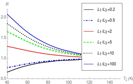
Fig. 6. Rectifying coefficient as a function of 𝑇 for several values of the ratio 𝐿 /𝐿 for the device of Fig. 5, at = 4, 𝜑 = 0.1, 𝑎 = 150 nm and 𝑇 = 150 K.
As shown in Fig. 6, the results of the bulk-porous-bulk device are more promising with the rectifying coefficient becoming larger than one with increasing -ratio. This is easily explained as for 𝐿 > 𝐿 the temperature at the bulk-porous interface (𝑇 in the direct case) is higher than in the case 𝐿 < 𝐿 , which causes a larger direct heat flux than the reverse one. It is interesting to observe that, depending on the value of -, the rectifying coefficient is smaller than one for 𝐿 /𝐿 < 1 and larger than one for 𝐿 /𝐿 > 1. Such a configuration presents a kind of reversibility in that the preferred direction of the heat will flow can be controlled through the geometrical configuration. Note finally that for the three-element system with = 100 (recall that = 4), the corresponding curve is akin to that of the two-element system with the same
40 60 80 100 120 140 TL K 0.5 1.0 1.5 2.0 R L1 L3 100 L1 L3 10 L1 L3 5 L1 L3 2 L1 L3 0.5 L1 L3 0.2
11
value = 4. This is understandable since for = 100, the system is comparable to a
bulk-porous one, with the right-side bulk element becoming negligible. It can be concluded that, concerning thermal rectification, the performance of the three-element system is not superior to that of the two-element. This is the motivation to discuss different systems in the next section. 4 Graded systems
4.1 Graded porosity
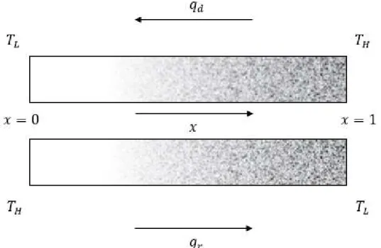
Instead of discontinuous configurations, we consider a sample with a gradually changing
porosity along the dimensionless 𝑥-axis (see Fig. 7), in other words 𝜑 = 𝜑(𝑥) and thus 𝑘 =
𝑘 (𝑇, 𝑥). In terms of non-dimensional quantities, Fourier’s law can be written as
= −
( , ) , (13)
wherein the temperature is scaled by the highest temperature 𝑇 , the space-coordinate by the length 𝐿 of the rod, the effective thermal conductivity by the bulk conductivity 𝑘 and the heat flux by 𝑘 𝑇 /𝐿. By selecting a graded structure, one avoids of course the problems raised by the presence of the aforementioned thermal boundary resistances.
Fig. 7. Sketch of the graded porosity distribution, with, at the left of the figure a zero porosity increasing gradually from zero to a maximum at the right. The direct flow (𝑞 ) refers to the hottest temperature 𝑇 imposed on the highest porosity side and the reverse (𝑞 ) to the same side subject to the lowest temperature 𝑇 .
It is assumed that the porosity varies along the sample according to the two following distributions:
12
𝜑 = 𝜑 (𝑎𝑥 + 𝑏𝑥 + 𝑐), (15)
with 𝜑 a constant and 𝑛, 𝑎, 𝑏 and 𝑐 non-dimensional quantities. The above dependencies of φ
with respect to x are expected to be reproducible in experiments that are actually still lacking. In equation (14), the space-dependency is monotonic so that 𝜑(𝑥 + 𝑑𝑥) > 𝜑(𝑥). For 𝑛 = 1, we have a linear relation of 𝜑(𝑥), for 𝑛 = 2, a quadratic one, etc. The coefficients 𝑎, 𝑏 and 𝑐 in (15) will be determined in the forthcoming by imposing that the porosity takes a maximum value at a given position in the sample. The direct and reverse heat fluxes can now be calculated by solving (9) in both directions. We keep the hot side temperature at 𝑇 = 150 K and the cold side temperature at 𝑇 = 40 K.
Fig. 8 shows the rectifying coefficient R as a function of the exponent 𝑛 of equation (14). R is increasing with 𝑛 and attains a maximum value around 𝑛 = 20. It should be noted
Fig. 8. Rectifying coefficient as a function of the porosity degree 𝑛 from equation (12) with 𝜑 = 0.1, 𝑎 = 150 nm, 𝑇 = 150 K and 𝑇 = 40 K.
However, such high 𝑛–values are from a technical point of view rather difficult to manage. Therefore, for the sake of simplicity, let 𝑛 be bounded to 𝑛 = 4. It will be shown later that choosing higher values of 𝑛 will not influence the value 𝑅 of significantly. Nonetheless, from a theoretical point of view, it is interesting to observe that 𝑅 will not grow indefinitely but is bounded by a finite maximum value.
Going now to equation (15), we are left with the determination of the unknown quantities 𝑎, 𝑏 and 𝑐. We first impose 𝜑(0) = 0, 𝜑(1) ≠ 0 and 0 < ( )< 1. Therefore, 𝜑 will reach a maximum in the region 0.5 < 𝑥 < 1. From 𝜑(0) = 0, follows that 𝑐 = 0. Requiring that 𝜑 is
maximum at 𝑥 leads to 𝑎 = − and 𝑏 = . In Fig. 9 is plotted the rectifying
coefficient as a function of 𝑥 . 0 10 20 30 40 50n 1.0 1.2 1.4 1.6 1.8 2.0R
13
Fig. 9. Rectifying coefficient as a function of the position 𝑥 corresponding to the maximum
value of the porosity given by Eq. (13) with 𝜑 = 0.1, 𝑎 = 150 nm, 𝑇 = 150 K and 𝑇 = 40 K.
The dashed line in Fig. 10 represents the value of 𝑅 for 𝑛 = 1 in Eq. (10). The results of Fig. 9 indicate that the parabolic dependence (13) of the porosity with respect to x does not provide better results than the linear one.
4.2 Graded pore size
We consider the same system as in the previous subsection (illustrated by Fig. 7), but instead of the porosity it is the pore size that is assumed to vary continuously along the system. So, we
still have 𝑘 = 𝑘 (𝑇, 𝑥) in equation (13), but now 𝜑 = 𝜑 = 𝑐𝑜𝑛𝑠𝑡𝑎𝑛𝑡 and 𝑎 = 𝑎 (𝑥).
It is assumed that the pore size varies linearly between a fixed minimum pore size 𝑎 , = 10
nm at 𝑥 = 1, and a variable maximum 𝑎 , at 𝑥 = 0. The dependence of the size with 𝑥 is
thus given by
𝑎 (𝑥) = 𝑎 , − 𝑎 , − 𝑎 , 𝑥. (16)
The rectifying coefficient as a function of 𝑎 , is represented in Fig.10.
Fig. 10. Rectifying coefficient as a function of the maximum pore size 𝑎 , , with 𝑎 (𝑥)
given by Eq. (14) at 𝜑 = 0.1, 𝑎 , = 10 nm, 𝑇 = 150 K and 𝑇 = 40 K.
0.5 0.6 0.7 0.8 0.9 1.0xmax 1.00 1.02 1.04 1.06 1.08 1.10R 2000 4000 6000 8000 10000ap,max nm 1.0 1.2 1.4 1.6 1.8 2.0R
14
It is shown that the rectifying coefficient is of the same order of magnitude as for the two-phase bulk/ porous medium, the best result is obtained with rather large pore sizes at 𝑥 = 1, around
𝑎 , = 5000 nm. The results of Figs. 9 and 10 suggest to combine both graded pore size and
graded porosity.
4.3 Combining graded porosity and pore size
Comparing Figs. 8 and 10 leads to the conclusion that a non-homogeneous porosity (with 𝑛 = 20 in equation (12)) leads to a rectifying coefficient R around 1.8 which is approximately the
same value obtained for non-homogeneous pore sizes with 𝑎 , = 5000 nm. The question
may therefore be raised whether a combination of both effects can further enhance the rectifying
coefficient. By taking 𝑛 = 20 in Eq. (14) and 𝑎 , = 5000 nm in Eq. (16), the rectifying
coefficient is raised up to 𝑅 = 2.24, which is quite higher than for each individual case. Even
if we take a more realistic value for n, say 𝑛 = 4 in equation (14), in combination with 𝑎 , =
5000 nm in Eq. (14), the rectifying coefficient is found to be given by
𝑅 = 2.12. (17)
Based on the different definitions used by some researchers and expressed by relations (2) and (3), one would have obtained
𝑅∗ = 0.36, (18)
𝑅∗∗ = 1.12. (19)
As mentioned earlier, we can see indeed that the selection of the value of 𝑛 has only a slight influence on the value of 𝑅. Summing up, we obtain the highest thermal rectifying coefficient by combining non-homogeneous porosity and variable pore size along the device. The most favourable configuration is the side with the highest porosity being associated with the smallest pore size. It has been checked that if the side with the highest porosity contains the largest pores, the rectifying coefficient falls down.
To give an idea of the order of magnitudes of the R-values recorded in previous studies, the values 𝑅 = 1.35, 1.43 and even 90 were obtained respectively in the case of materials with asymmetric shapes [32], LaCo oxides [19] and shape memory alloys [4]. In [33], a maximum value of 𝑅∗ = 0.39 is found. A higher thermal rectification 𝑅∗ = 0.67 is obtained by pressurizing an aluminium-stainless steel combination [34]. More recently, molecular dynamics
simulations of asymmetric graphene ribbons predict 𝑅∗ = 0.33 − 0.64 [35] depending on the
length of the device, and 𝑅∗ = 0.13 at 25 K for argon-krypton devices [36]. It appears that our R- values are amongst the highest ones, which suggests to open the way to the building-up of a new class of rectifiers based on nanoporous materials.
5 Conclusions
We have calculated the thermal rectifying coefficient 𝑅 for several types of devices: a bulk-porous homogeneous system, bulk-bulk-porous-bulk and bulk-porous-bulk-bulk-porous homogeneous systems and finally graded systems, wherein the physical properties vary gradually with position along the system. In the latter case, we have considered three different kinds of non-homogeneity: either in the form of a graded porosity, or a graded pore size or a combination of the two. The results are promising, as they indicate that some configurations yield high 𝑅-values of the order
15
of 2, and even higher. These values are much larger than 𝑅 = 1.43 obtained in an oxide thermal rectifier [19] and comparable to 𝑅 = 2.5, calculated for carbon nanocones [37].
Our analysis has shown that finally, it is the homogeneous bulk-porous system that offers the most promising perspectives. The more sophisticated structures with three elements (bulk-porous-bulk) are less performing. The non-homogeneous configurations analysed in this work yield lower values of the rectifying coefficient than the homogeneous bulk-porous system, except if both the porosity and the pore size change concomitantly along the device, with the highest porosity and smallest pore size on the same side of the sample. The latter configuration corresponds to the highest rectifying coefficients found in this work, namely 𝑅 = 2.24 and 𝑅 = 2.12.
The present study confirms that heat transport through the aforementioned described structures is of ballistic nature. Indeed, at small pore sizes, 𝐾𝑛 becomes large and the thermal conductivity decreases considerably. The same property holds true for an increasing porosity. At higher porosity, the phonons in the silicon matrix will encounter more obstacles, which reduces the
efficiency of heat transfer. If, in contrast, 𝐾𝑛 tends to zero, expression (4) reduces to 𝑘 =
𝑘 (1 − 𝜑) , in which case the behaviour of the thermal conductivity as a function of temperature will be reminiscent of that in the bulk.
Of course, although the theoretical model proposed here is not supported by experimental data, it may shed more light on the active subject of thermal rectification with the hope to inspire further experimental investigations in the field.
Acknowledgments
H.M. acknowledges financial support of BelSPo. G.L. acknowledges the support of the 9th “Projet de collaboration Wallonie-Bruxelles-Québec 2015-2017” under contract RI 15. D.J. acknowledges the support of Spanish Ministry of Economy and Competitiveness under grant FIS2012-32099, and of Ministry of Science and Innovation under grant CSD2010-00044 (Consolider project Nanotherm). We have appreciated fruitful discussions and valuable comments with our colleagues M. Grmela, Ch. Dubois, A. Behrang (Ecole Polytechnique de Montreal) and M. Criado-Sancho (UNED, Madrid).
References
[1] M. Criado-Sancho, L.F. del Castillo, J. Casas-Vázquez, D. Jou, Theoretical analysis of thermal rectification in a bulk Si/nanoporous Si device, Phys. Lett. A, 376 (2012), pp. 1641-1644
[2] F. X. Alvarez, D. Jou, A. Sellitto, Pore-size dependence of the thermal conductivity of porous silicon: A phonon hydrodynamic approach, Appl. Phys. Lett. 97 (2010), p. 033103 [3] G. Lebon, G. Lebon, D. Jou, J. Casas-Vázquez, Understanding Non-Equilibrium Thermodynamics, Springer, Berlin, (2008)
[4] C.Y. Tso, Christopher Y.H. Chao, Solid-state thermal diode with shape memory alloys, Int. J. Heat Mass Transfer 93 (2016), pp. 605-611
[5] R. R Somers II, L. S. Fletcher, R. D.Flack, Explanation of thermal rectification. AIAA Journal, 25(4) (1987). Pp. 620-621
[6] M. A. Dos Santos Bernardes, Experimental evidence of the working principle of thermal diodes based on thermal stress and thermal contact conductance –thermal semiconductors, Int. J. Heat Mass Transfer 73 (2014), pp. 354-357
[7] L. Wang, B. Li, Phononics gets hot, Phys. World, 21 (2008), pp. 27-29
[8] N. Li, J. Ren, L. Wang, G. Zhang, P. Hänggi, B. Li, Colloquium: Phononics: manipulating heat flow with electronic analogs and beyond, Rev. Mod. Phys. 84 (2012), p. 1045
16
[9] M. Maldovan, Sound and heat revolutions in phononics, Nature 503 (2013), pp. 209-217 [10] C. Starr, C. (1936). The copper oxide rectifier, J. Appl. Phys, 7 (1936), pp. 15-19
[11] D.B. Go , M. Sen, On the condition of thermal rectification using bulk materials, J. Heat Transfer 132 (12) (2010) p. 124502
[12] J. Hu, X. Ruan, Y. P. Chen, (2009). Thermal conductivity and thermal rectification in graphene nanoribbons: a molecular dynamics study. Nano Lett, 9 (7) (2009), pp. 2730-2735 [13] C. W. Chang, D. Okawa, A. Majumdar, A. Zettl, (2006). Solid-state thermal rectifier, Science, 314 (5802) (2006), pp. 1121-1124
[14] B. Li, L. Wang, G. Casati, G. (2004). Thermal diode: Rectification of heat flux, Phys. Rev. Lett, 93 (18) (2004), p. 184301
[15] I. Catarino, G. Bonfait, L. Duband, Neon gas-gap heat switch, Cryogenics 48(1) (2008) pp.17-25
[16] J.B. Boryeko, Y. Zhao, C.H.Chen, Planar jumping drop thermal diodes, Appl. Phys. Leett. 99(23) (2011) p. 234105.
[17] P. Ben-Abdallah, S.A. Biehs, Phase-change radiative thermal diode, Appl. Phys. Lett. 103(19) (2013) p. 191907
[18] C. Dames, Solid-state thermal rectification with existing bulk materials. J. Heat Transfer, 131(6) (2009), p. 061301
[19] W. Kobayashi, Y. Teraoka, I. Terasaki, An oxide thermal rectifier, Appl. Phys. Lett. 95 (2009), p. 171905
[20] M. Criado-Sancho, D. Jou, Heat transport in bulk/nanoporous/bulk silicon devices, Phys. Lett. A, 377 (2013), pp. 486-490
[21] I. Sumirat, Y. Ando, S. Shimamura, Theoretical consideration of the effect of porosity on thermal conductivity of porous materials, J. Porous Mater. 13 (2006), pp. 439-443 [22] H. Machrafi, G. Lebon, Size and porosity effects on thermal conductivity of nanoporous material with an extension to nanoporous particles embedded in a host matrix, Phys. Lett. A 379 (2015), pp. 968-973
[23] D. Jou, J. Casas-Vazquez, G. Lebon, Extended Irreversible Thermodynamics, 4th
edition Springer, Berlin (2010).
[24]M. Wang, N. Pan, Predictions of effective physical properties of complex multiphase
materials, Mater. Sci. Eng. R 63 (2008), pp. 1-30
[25] G. Lebon, H. Machrafi, M. Grmela, An extended irreversible thermodynamic modelling of sizedependent thermal conductivity of spherical nanoparticles dispersed in semiconductors, Proc. Roy. Soc. A, 471 (2015), p. 20150144
[26] J. Callaway, Model for lattice thermal conductivity at low temperature, Phys. Rev. 113 (1959), pp. 1046-1051
[27] N. Mingo, L. Yang, D. Li, A. Majumdar, Predicting the thermal conductivity of Si and Ge nanowires, Nano Lett. 3 (2003), pp. 1713-1716
[28] G. Gesele, J. Linsmeier, V. Drach, J. Fricke, R. Arens-Fischer, Temperature-dependent thermal conductivity of porous silicon, J. Phys. D: Appl. Phys. 30 (1997), pp. 2911-2916 [29] G. Benedetto, L. Boarino, R. Spagnolo, Evaluation of thermal conductivity of porous silicon layers by a photoacoustic method, Appl. Phys. A: Mater. Sci. Process. 64 (1997), pp. 155-159
[30] E.T. Swartz, R.O. Pohl, Thermal boundary resistance, Rev.Mod. Phys. 61(3) (1969) pp.605-664
[31] G. Chen, Thermal conductivity and ballistic-phonon transport in the cross-plane direction of superlattices, Phys. Rev. B 57(1998)14958-14973
[32] D. Sawaki, W. Kobayashi, Y. Moritomo, I. Terasaki, Thermal rectification in bulk materials with asymmetric shape, Appl. Phys. Lett. 98 (2011), p. 081915.
17
[33] D. G. Walker, Thermal rectification mechanisms including noncontinuum effects, in: proceedings of the Joint ASME-ISHMT Heat Transfer Conference, IIT Guwahati, India, 2006. [34] M. H. Barzelay, K. N. Tong, G. F. Holloway, Effects of pressure on thermal conductance of contact joints, Technical Report 3295, NACA (1955).
[35] N. Yang, G. Zhang, B. Li, Thermal rectification in asymmetric graphene ribbons, Appl. Phys. Lett. 95 (2009), p. 033107
[36] N. Roberts, D. Walker, Molecular dynamics simulation of thermal transport with asymmetric and rough interfaces, in: Proceedings of International Symposium on Transport Phenomena, University of Iceland, Reykjavik, Iceland (2008).
[37] N. Yang, G. Zhang, B. Li, Carbon nanocone: a promising thermal rectifier, Appl. Phys. Lett. 93 (2008), p. 243111.