HAL Id: tel-01352817
https://hal.inria.fr/tel-01352817
Submitted on 18 Aug 2016
HAL is a multi-disciplinary open access archive for the deposit and dissemination of sci-entific research documents, whether they are pub-lished or not. The documents may come from teaching and research institutions in France or abroad, or from public or private research centers.
L’archive ouverte pluridisciplinaire HAL, est destinée au dépôt et à la diffusion de documents scientifiques de niveau recherche, publiés ou non, émanant des établissements d’enseignement et de recherche français ou étrangers, des laboratoires publics ou privés.
Metamodelisation to support Test and Evolution
Anne Etien
To cite this version:
Anne Etien. Metamodelisation to support Test and Evolution. Langage de programmation [cs.PL]. Université de Lille, 2016. �tel-01352817�
Sp´ecialit´e Informatique Ecole doctorale Science Pour l’Ing´´ enieur (Lille)
Metamodelisation to support
Test and Evolution
Habilitation `
a Diriger les Recherches
Universit´
e Lille 1, Sciences et Technologies
(sp´ecialit´e informatique)pr´esent´ee et soutenue publiquement le 28 juin 2016
par
Anne Etien
Composition du jury
Pr´esident : Mme Laurence Duchien Rapporteurs : M. Serge Demeyer,
Mme Marianne Huchard, M. Jurgen Vinju
Examinateur : M. Xavier Blanc
Garant : M. St´ephane Ducasse
Centre de Recherche en Informatique Signal et Automatique de Lille — UMR CNRS 9189 INRIA Lille - Nord Europe
Contents
1 Introduction 1
1.1 Goal of this Document . . . 1
1.2 Software Maintenance, Testing and Evolution . . . 2
1.3 Models Everywhere . . . 4
1.4 Content of this Document . . . 4
2 Designing Model Transformation Chains 7 2.1 Problems . . . 7
2.2 Previous State of the Art . . . 8
2.3 Contributions . . . 11
2.3.1 Localised Transformations . . . 11
2.3.2 Composition of Localised Transformations . . . 13
2.3.3 Building Model Transformation Chains . . . 15
2.3.4 Localised Transformations Characteristics . . . 16
2.4 Perspectives . . . 17
3 Software Architecture Modifications 19 3.1 Problems . . . 19
3.2 Previous State of the Art . . . 20
3.3 Contributions . . . 22
3.3.1 Architectural Modifications and Constraint Validations . . 22
3.3.2 Transformation Pattern Definition . . . 23
3.3.3 Relevance of Transformation Patterns . . . 26
3.3.4 Automating Transformation Pattern Application . . . 28
3.4 Perspectives . . . 29
4 Testing Supported by Metamodelling 33 4.1 Problems . . . 33
4.2 Previous State of the Art . . . 34
4.3 Contributions . . . 36 i
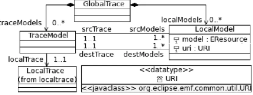
4.3.1 Trace Mechanism . . . 36
4.3.2 Error localisation . . . 38
4.3.3 Mutation Analysis and Model Transformations . . . 39
4.3.4 Test Set Selection after a Change in the Program . . . 42
4.4 Perspectives . . . 48
5 Co-evolution Supported by Metamodels 51 5.1 Problems . . . 51
5.2 Previous State of the Art . . . 52
5.3 Contributions . . . 55
5.3.1 Transformation-Metamodel Co-evolution . . . 55
5.3.2 Database and Program Co-Evolution. . . 57
5.4 Perspectives . . . 61
6 Conclusion and Perspectives 63 6.1 Main Results . . . 63
C
HAPTER1
Introduction
During ten years, I have been working on two different domains Model Driven Engineeringand Software Maintenance but with a single target: Designing systems of good quality, easily maintainable. The reasoning was also the same: I proposed solutions based on metamodels or models to provide genericity and independence from the programming languages of the results. The considered systems are either chains of model transformations (i.e. not the program generated from models but the, model based, compiler itself) or traditional programs. Quality can be ensured and measured from different ways. In this document, I only focus on tests.
1.1
Goal of this Document
In this document of Habilitation to Supervise Research, I aimed at illustrating three complementary qualities that I consider necessary to supervise research:
• ability to supervise novice or young researchers. Our mission as supervisor is to teach novice and young researchers to search without mandatorily ob-taining results, to search again and find relevant results and to present them. I had the opportunity to supervise 4 PhD students (including one who already defended) and 4 master students. I also accompanied in their research, one post doc and one ATER.
• ability to collaborate. In my opinion, research is synonym of exchange. Ex-change between people from different horizons with different backgrounds and ways of thinking. Collaborations can be either academic, between re-searchers, or industrial to answer real problems. I worked in close collab-oration with French or international researchers. Moreover, since I had the opportunity to do my own research, I have been trying to answer concrete and real issues. Some were initiated by companies, others were transferred to the industry.
• ability to have a vision. Research in a domain does not stop with the defense of a PhD student, or the end of a project. On the contrary, it is mostly the occasion to raise new issues. Having a vision, is also having the ability to decompose long term research topics into short or mid term issues.
All the results presented in this document were reached in collaboration with either a novice researcher that I supervised or a colleague. Details of the presented results can be found in articles published in international journals, conferences and workshops.
1.2
Software Maintenance, Testing and Evolution
This document presents my work of these ten last years. My career follows a “tra-ditional" path. After a PhD at the University Paris 1 on information systems, I came to Lille in 2006 for a postdoctoral stay to work on model transformations in the Dart team common to Inria and Lifl Lab (now CRIStAL). After one year, I was enrolled as associate professor teaching at Polytech Lille and doing my research in the Dart team. Its core business was real-time embedded systems dealing with massively parallel data. The embedded systems were generated from models using model transformation chains. My research concerned the chains. In 2011, the Inria team stopped. A new one was created without any reference to models. My work had no place in this new organisation. After trying during one year to work alone or move to somewhere else, I finally decided to join the RMod team common to Inria and Lifl lab. The goal of RMoD is to support remodularisation and development of modular object-oriented applications. This objective is tackled from two com-plementary perspectives: reengineering and constructs for dynamic programming languages. I have been working on the reengineering part where we propose new analyses to understand and restructure existing large applications based on abstract representations.
Looking back to these years, two topics are constantly studied: testing and evolution. The analysed systems are different, model transformation chains or tra-ditional programs but the main objective remains the same: ease maintenance. It can be noticed that this thematic was already strongly present in my PhD disserta-tion. Moreover, the used means i.e., modelling and metamodelling also federates my research.
Before briefly presenting the topics tackled in this document, I explain why I am studying software maintenance.
Why Software Maintenance? Several studies showed that activities after deliv-ery are pre-dominant in software engineering and correspond to 90% of the total cost of a typical software [Pigoski 1997, Seacord 2003]. These activities corre-spond to software maintenance that is the modification of a software product after delivery to correct faults, to improve performance or other attributes [ISO 2006]. Past studies (reported in [Pigoski 1997]) showed that, contrary to common belief, correctivemaintenance (i.e. diagnosing and fixing errors) represents only a small part of all maintenance (21%). Most software maintenance (50%) is done to add
1.2. SOFTWARE MAINTENANCE, TESTING AND EVOLUTION 3 new features (perfective maintenance). The modification of the system to cope with changes in the software environment (adaptive maintenance) corresponds to 25%. The system is modified to increase its maintainability or reliability (4%) to prevent problems in the future (preventive maintenance).
Moreover, Lehman’s first law of software evolution (law of Continuing Change, [Lehman 1980]) specifies that “a program that is used undergoes continual change or becomes progressively less useful." A corollary to this law is that software main-tenance is a sign of success: considering the costs associated to software mainte-nance, it is performed only for software systems which utility is perceived as more valuable than this cost. This is a conclusion that goes against the usual perception of the activity, but maintenance actually means that a system is useful and that its users see a value in its continuing operation.
Anticipation and Architecture Modifications. Object, aspect and model par-adigms were introduced to enhance reusability, modularity and ease successive evolutions the software systems meet. Even if these paradigms were introduced for these purposes, for each software system, maintenance must be anticipated from the design phase [Budgen 2003]. However, everything cannot be anticipated and anyway, according to Lehman’s second law (law of Increasing Complexity, [Lehman 1980]) “as a program evolves, its complexity increases unless work is done to maintain or reduce it". Modifications of the software architecture is re-quired to reduce complexity and to bring new and solid bases for future evolutions. Support in the form of concepts, methods, techniques, and tools for recognizing, confronting, and managing architecture modifications is required [Avgeriou 2013].
Test to Ensure Quality and Ease Maintenance. According to Beck, the most important rule of simple design is "Passes the tests" [Beck 2004]. The point is that whatever else is done with a software system, the primary aim is that it works as intended and tests are there to verify that this happens.
Depending on their nature, tests answer different purposes. For example, they enable the developer to identify and locate errors in the code that thus, will not occur later. Moreover, tests ensure non regression after an evolution by checking that what was changed did not impact the rest of the system. For these two reasons, presence of tests positively acts on maintenance.
However, covering the whole code and all the alternatives with tests may not be possible in the context of large systems. Consequently, test sets have to be qualified to be considered good enough to highlight errors. On the other hand, when tests are numerous and code evolves it can be very long to execute all the tests after a change. For this reason, and also because unfortunately tests are often considered as lost time, big companies may not always put as much emphasis on tests as they should. Errors are thus detected only after delivery.
Software Ecosystem. Software artefacts are not independent anymore, they con-stitute ecosystems where the evolution of one element impacts the others. Con-sequently, evolution has to be thought in terms of co-evolution, the evolution of different artifacts in parallel or in response to a first change.
1.3
Models Everywhere
Model Driven Engineering. Model driven engineering and model transforma-tion were introduced in the early 2000s with the goal to develop once and generate several times. If the theory was attractive, model transformation applications on real cases were chaotic. Indeed, model transformations were not designed to be maintained later. This new paradigm, model as first class artefacts, required to adapt existing technologies in term of design, test, maintenance and evolution.
This document tackles the issues of evolution, test and maintenance, mainly in the context of model driven engineering. Thus, the studied software artefacts are models, metamodels, transformations and chains. A transformation is defined with potentially several input and several output metamodels. It enables the generation of models conforming the output metamodels from models conforming the input metamodels. A chain is a sequence of transformations where the output models of a transformation are the inputs of the following transformations.
Metamodelling as support. To provide generic results, modelling or metamod-elling are widely used as the fundament of the approaches proposed in this docu-ment whatever the type of software system (i.e. model transformation chain or tra-ditional program). Concretely, the different artefacts (software, language, change, operator) were abstracted and reasoning is performed on these abstractions. Con-sequently, they can easily be adapted to other systems, languages, artefacts.
1.4
Content of this Document
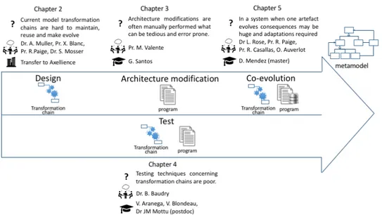
This document tackles two types of software systems (model transformation chains and traditional programs) at different steps of their life cycle. Design to foresee maintenance, test, architecture modifications and co-evolution are handled. Results reported in this document rely on metamodelisation. Figure 1.1 sketches and sums up the content of this document.
Each chapter follows the same structure. First, the problem is briefly intro-duced. Second, a state of the art as it was when the work was realised is presented and discussed. Third, the contributions are described. Finally perspectives and conclusions are drawn. The presented results were published in international jour-nals, conferences or workshops and readers needing more details are invited to read
1.4. CONTENT OF THIS DOCUMENT 5
Figure 1.1: Overview of the problems tackled in the document
these papers.
Chapter 2 proposes a new way to design model transformations to enhance reusability, maintainability and scalability of transformation chains. This mostly comes out of collaborations with Dr Alexis Muller, Prof. Xavier Blanc, Prof. Richard Paige and Dr Sebastien Mosser.
Chapter 3 aims to provide support in the form of concepts, methods, tech-niques, and tools for different categories of architecture modifications. This chap-ter exposes the results conduced in the context of Gustavo Jansen Santos thesis and a collaboration with Prof. Marco Tulio Valente.
Chapter 4 focuses on data test sets. It provides generic mechanisms, in the context of model transformations to improve test data sets. It also studies problems and impact of test set selection in the context of traditional software when the test set is too large to be run entirely after a change. This chapter mainly presents results obtained (i) in the context of Vincent Aranega’s thesis and the postdoctoral stay of Dr Jean-Marie Mottu and (ii) in the context of Vincent Blondeau’s CIFRE thesis with Worldline.
Chapter 5 studies the co-evolution of different system artefacts. Even if the artefacts are different, the co-evolution mechanism is very similar in the two stud-ied cases: metamodel-transformation and database schema-program. This chapter presents results conducted in the context of David Mendez’ master internship and collaborations with Dr Louis Rose and Prof. Richard Paige, with Prof. Rubby Casallas and with Olivier Auverlot, CRIStAL Information System architect.
C
HAPTER2
Designing Model Transformation
Chains
to Ease Maintenance and
Evolution
2.1
Problems
For a decade, Model Driven Engineering (MDE) has been widely applied. Large and complicated languages are used – e.g., UML 2.x and profiles such as SysML1 or MARTE2. Consequently, large transformations are more likely to be developed; examples have been published of transformations counting tens of thousands of lines of code. Such transformations have substantial drawbacks [Pilgrim 2008], including reduced opportunities for reuse, reduced scalability, poor separation of concerns, limited learnability, and undesirable sensitivity to changes. Other re-search argued that focusing on the engineering of transformations, and improving scalability, maintainability and reusability of transformations, is now essential, to improve the uptake of MDE [Wagelaar 2009] and to make transformations practi-cal and capable of being systematipracti-cally engineered [Cordy 2009].
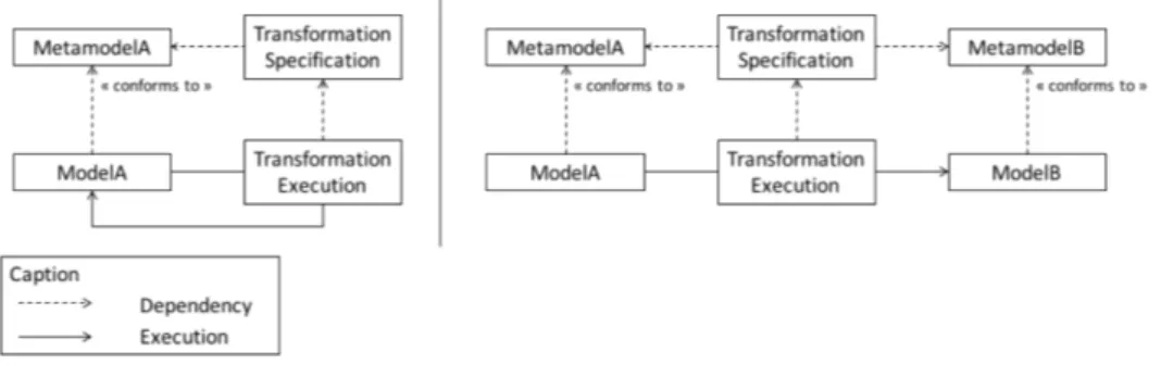
Several classifications considered model transformations according to different criteria [Czarnecki 2003]. Here we focus on the relationship between source and target criterion that introduces two different transformation types: in-place or out-place, also called in-out transformation. In in-place transformations, the input and output metamodels are the same, the input model conforms to them and is modified in place. Refactoring transformations fall into this category. Such transformations are often very limited in terms of number of involved metamodel concepts and in terms of performed modifications. In case of in-out transformation, the input and output metamodels are often different, but this is not mandatory. The output model is created from scratch. To create an output model element, the metamodel con-cept that is instantiated has to be handled by the transformation. Traditional in-out transformations must manage the whole input and output metamodel. Model
trans-1
http://www.omgsysml.org/ 2
http://www.omg.org/spec/MARTE/
formation chains are mostly composed of in-out transformation to refine details and finally generate code. Figure 2.1 sketches these two types of transformation.
Figure 2.1: In place transformation on the left; in-out transformation on the right Small transformations dedicated to a specific purpose are more easily main-tainable or reusable than big transformations dealing with large and complicated metamodels. However, as briefly explained they have to be either in place and deal with the same input and output metamodels or in-out and manage all the metamodel concepts, that in case of big metamodels can quickly become huge. The purpose of this chapter is to tackle this contradiction. The idea is to combine advantages of both of these transformation types to get small dedicated transformations whose input and output metamodels may be different and count several hundred of con-cepts.
This chapter deals with model transformation chain as studied software sys-tem. It aims to enhance maintainability, reusability and modularity in this type of system. For this purpose, metamodeling techniques are used.
2.2
Previous State of the Art
This section presents the state of the art about model transformation chains as it was around 2005-2010, when the work presented here took place.
In the case of traditional systems, identification of reusable artefacts can be done from scratch or by decomposition of existing software system. In the case of model transformations the same approaches can be considered. When small transformations are built, they need to be composed into chains. First we present the existing decomposition approaches and their limits. Then we briefly introduce the composition proposals. Finally, since generic transformations also answer to the reusability requirement, we briefly explain the existing approaches and their drawbacks.
2.2. PREVIOUS STATE OF THE ART 9 Decomposition of transformations. Hemel et al. describe the decomposition of a code generator (i.e. a model transformation chain leading to code) into small transformations [Hemel 2008]. The authors introduce two types of modularity: vertical and horizontal. Vertical modularity is used to reduce the semantic gap between input and output models. It is achieved by introducing several interme-diary transformations that gradually transforms a high-level input model into an implementation. Horizontal modularity is achieved by supporting the definition of plugins which implement all aspects of a language. If vertical modularity was com-mon already at that time as suggested by the Model Driven Architecture (MDA) process, horizontal modularity was new and it is what we wanted to tackle. Sim-ilarly, Vanhooff et al. highlighted the benefits of breaking up large monolithic transformations into smaller units that are more easily definable, reusable, adapt-able [Vanhoof 2005]. In these approaches, no information is given concerning the “localised” character of the transformations. The examples of these papers only concern refactorings (i.e. in-place transformation with same input and output metamodels).
Oldevik provides a framework to build composite transformations from reus-able transformations [Oldevik 2005]. The author assumes that a library of existing transformations is readily available. The granularity/locality degree of the trans-formations is not specified.
Olsen et al. define a reusable transformation [as] a transformation that can be used in several contexts to produce a required asset[Olsen 2006]. In practice, the smaller transformations are, the more they are reusable. Furthermore, the authors identify several techniques allowing the reuse of transformations such as speciali-sation, parametrisation and chaining. Nevertheless, no indication is provided on the characteristics of the transformations or on the way to practically and concretely reuse transformations.
Sànchez and Garcia argued that model transformation facilities were too fo-cused on rules3 and patterns4 and should be tackled at a coarser-grained level [Sanchez Cuadrado 2008]. To make model transformation reusable as a whole, authors propose the factorisation and composition techniques. Factorisation tech-niques aim at extracting a common part of two existing transformations to define a new transformation. Composition creates a new transformation from two existing ones. Those techniques have a major drawback. They require that the intersection of the input and the output metamodels (viewed as set of concepts) is not empty.
Chaining transformations. Rivera et al. provide a model transformation or-chestration tool to support the construction of complex model transformations
3
As a program is composed of functions or methods, model transformations are composed of rules.
4The patterns define the application condition of a rule to modify the source elements (in case of in-place transformation) or to create target ones (in case of out-place transformation)
from those previously defined [Rivera 2009]. The transformations are expressed as UML activities. As such, they can be chained using different UML operators: composition, conditional composition, parallel composition and loop. Only hetero-geneous transformations (i.e. transformations whose input and output metamodels are different) can be chained. The reuse of a transformation in different chains is thus limited by the required inclusion of the output metamodel of one transforma-tion in the input metamodel of the next one. This approach thus has restrictransforma-tions in terms of reusability and adaptability.
Wagelaar et al. propose the mechanism of module superimposition to com-pose small and reusable transformation [Wagelaar 2009]. This mechanism allows them to overlay several transformation definitions on top of each other and then to execute them as one transformation. This approach depends from transformation language characteristics and cannot be easily adapted to other languages.
Mens et al. explore the problem of structural evolution conflicts by using graph transformation and critical pair analysis [Mens 2005a]. The studied transforma-tions are refactorings (that are in place transformatransforma-tions). The operatransforma-tions that a transformation can perform in such cases are precisely prescribed. Nine operations are highlighted in the paper. With such a limited number, it is possible to study in detail when the operations can be chained and, when doing so, if they are commu-tative.
Generic transformation. Generic programming techniques were transposed to graph transformation to increase their reusability across different metamod-els [Cuadrado 2011, de Lara 2012]. For this purpose, they build generic model transformation templates, i.e. transformation in which the source or the target do-main contains variable types. The requirements for the variable types (needed properties, associations, etc.) are specified through a concept. Concepts and con-crete metamodels are bound to automatically instantiate a concon-crete transformation from the template. The resulting transformation can be executed as any other trans-formation on regular instances of the bound metamodels.
Sen et al. propose to define reusable transformations with generic metamod-els [Sen 2012]. The actual transformations result from an adaptation of a generic transformation using an aspect based approach. A model typing relationship binds the elements of the generic metamodel and those of the specific metamodels.
These two approaches have a major drawback, the concept, or the generic meta-model must cover the whole specific metameta-model to which it is bound what rarely occurs in practice.
Summary. This state of the art highlights (i) the requirement of reusability in transformation chains and (ii) the necessity to introduce a new type of transforma-tion conjugating in-place and out place advantages.
2.3. CONTRIBUTIONS 11
2.3
Contributions
To enhance transformation reusability, we introduced a new type of transformation that conjugates the advantages of both in-place and in-out transformation; the lo-calised transformations. This new type of transformation implies a new way to compose transformations and to build transformation chains.
2.3.1 Localised Transformations
A localised transformation [Etien 2015] applies to a tightly prescribed, typically small-in-context part of an input model; all other parts of the input model are not affected or changed by the localised transformation.
Localised transformations focus on a specific purpose, for example memory management or task scheduling in the context of massively parallel embedded sys-tem generations. Thus some elements in the input model are identical in the output model, i.e., they will simply be copied over from input to output model. Manu-ally writing such transformation logic is tedious and error prone; moreover, in the case of complicated transformations, such logic (which may be repeated in differ-ent parts of a chain of transformations) increases interdependencies and can reduce reusability and maintainability.
Thus, to increase flexibility we distinguish two parts of a localised transfor-mation: the part that captures the essential transformation logic, and the part that copies that subset of the input model to the output model. In this way, a localised transformation can be specified with small (intermediate) metamodels only con-taining the concepts used and affected by the transformation. However, the models on which the transformation is executed conform to the whole metamodel, and not solely the subset on which the transformation is specified. To solve this issue, we provided an extension mechanism to extend the input and output metamodels of a localised transformation [Etien 2010]. The extension mechanism, combined with the implicit copy, provide the means to manage the transformation engineering process.
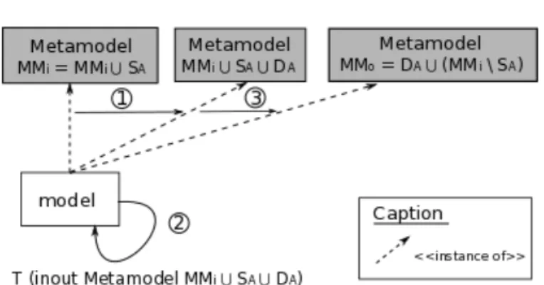
The Extend operator extends the notion of in-place transformation to trans-formations where input and output metamodels may be different, but the copy/i-dentity function is implicit. Concretely, the input model is considered an instance of the union of the input and the output metamodel (1). Then, this model is copied and the transformation is executed as an in-place transformation on this copy (2). Finally, the model is considered an instance of the output metamodel since all the elements of the input model instantiating a concept of the input metamodel not present in the output one were consumed to produce new elements (3). Figure 2.2 presents the Extend operator mechanism with these three phases.
Figure 2.2: Schema of the Extend mechanism
SAto the destination metamodel DA(t : SA→ DA) and M Mian ordinary
meta-model. ExtendM Mi(t) is a transformation T from the SA∪ M Mimetamodel
5to
the metamodel M Mo(T : M Mi∪ SA→ M Mo), having the same behaviour that
t such that:
• M Mo = DA ∪ (M Mi \ SA), where M Mi \ SA is the part of the
meta-model M Mithat was not involved in the transformation, i.e. the part whose
instances are implicitly copied
• T (m) = t(m) if m is a model instance of the metamodel SA, applying t or
its extended version T is exactly the same
• T (m) = m if m is a model instance of the metamodel M Mi \ SA, m is
simply copied since it does not contain elements instantiating a concept of SA
• T (m) = T (n) ∪ (m \ n) with n the part of the m model typed by SA. T is
composed of two parts, the transformation t and the copy.
(DA\ SA 6= ∅) implies that t (and thus also T ) introduce new concepts not in
M Mi; correspondingly, (SA\ DA 6= ∅) means that some concepts are consumed
by t (and thus also T ). A concept is consumed by a transformation if it exists in the input metamodel of the transformation but not in the output metamodel. Thus, the execution of the transformation aims to remove all instances of those concepts present in the input model. In theory, it is always possible to choose M Mi such
5
We adopt the metamodel, model and conformance definitions established by Alanen et al.[Alanen 2008]. A metamodel is a set of classes and a set of properties owned by the classes. A model is a set of elements and a set of slots. Each element is typed as a class in a metamodel. Each slot is owned by an element and corresponds to a property in a metamodel. From these def-initions, the union, the intersection and the difference are defined on both metamodels and models respectively as the union, the intersection or the difference of each set defining the metamodels or the models.
2.3. CONTRIBUTIONS 13 that SAis included in M Mi; however, in practice, M Mi is not arbitrarily chosen,
it depends on the chain and corresponds to the input metamodel of the chain plus (resp. minus) those concepts introduced (resp. removed) by other transformations. Indeed, if SA is not a subpart of M Mi, this means that some concepts are useful
to the execution of the transformation t but no instance will be found in any input model: another localised transformation introducing these concepts must be exe-cuted beforehand. Finally, extending t with various metamodels M Mienables to
easily reuse t.
The notion of localised transformation is an addition to the classifications es-tablished by Czarnecki and Mens [Czarnecki 2003, Mens 2005c], where the input and output metamodels are different, but with some concepts in common. Mens et al. distinguish heterogeneous transformations, where the input and the output metamodels are different, from endogenous transformation defined on a unique metamodel. He explicitly specifies that "exogenous transformations are always out-place". Czarnecki differentiates approaches mandating the production of a new model from nothing, from others modifying the input model (e.g. in-place transformation). These classifications do not consider sharing and copying with potentially different input and output metamodels inherent in localised transfor-mations. The notion of localised transformation is therefore a new contribution to these taxonomies.
The notion of localised transformation is the result of a collaboration with Dr Alexis Muller and Professor Richard Paige [Etien 2015]. It has been implemented in Gaspard6in the context of embedded systems [Gamatié 2011]. A transfer of the transformation engine to Axellience, an Inria spin-off, occurred in 2012.
2.3.2 Composition of Localised Transformations
Once individual localised transformations have been defined, they must be com-posed to form a transformation chain and produce the expected result. Defining this composition is not trivial: if the input metamodel for the chain is known, the or-der in which localised transformations are executed has to be calculated precisely, since some orderings do not lead to models conforming the output metamodel (e.g., by leaving an intermediate model in an inconsistent state that cannot be reconciled by any successive subchain of localised transformations).
Traditionally, input and output metamodels are either completely separated or form only one. We formally defined rules to identify valid compositions of trans-formations [Etien 2010]. These rules can be applied to localised transtrans-formations, since they consider transformations whose input and output metamodels overlap.
6
Gaspard is a hardware/software co-design environment dedicated to high performance embed-ded systems based on massively regular parallelism. It has been developed at Inria Lille Nord Europe by the Dart team to which I belonged (https://gforge.inria.fr/frs/?group id=768).
They rely on a structural analysis of the small metamodels involved in each lo-calised transformation. We briefly summarise this here.
Consider two localised transformations, tA: SA→ DA, and tB: SB→ DB.
Definition: Chaining of localised transformations. tAand tB, can be chained
if there exists a metamodel M MA on which the first transformation can be
ex-tended using the Extend operator and if the concepts used by the second transfor-mation are included in the output metamodel of the first extended transfortransfor-mation. More formally, ∃ M MAsuch as SB ⊆ DA∪ (M MA\ SA). This inclusion implies
that the concepts used by the second transformation (tB) are not consumed by the
first one (tA) i.e. SB∩ (SA\ DA) = ∅.
From this definition, it is possible to extract the following property:
Property: Chaining of extended transformations. If tAand tBcan be chained
then their extended version TAand TB can also be chained corresponding to the
classical TA◦TB, with TA= ExtendM MA(tA) and TB= ExtendDA∪(M MA\SA)(tB) The input metamodels SAand SBare subsets of M Miwith M Mi = M MA∪
SA (plus eventually other concepts created by other localised transformations).
Three cases may occur:
1. tAandtBcan only be combined in one order (tAthentBfor example). This
means that tAcan be chained with tBor tBcan be chained with tA.
2. tA andtB can be combined in both orders. The order of the two localised
transformations tA and tB can be swapped if tAcan be combined with tB
and vice-versa i.e. the chaining definition is applied in both orders. But we cannot guarantee that in both orders, the resulting models are equivalent. If the input metamodels of the two transformations tA and tB have no
com-mon elements and if the concepts required by tA(respectively tB) are not
produced by tB (respectively tA), they can be combined and the resulting
model does not depend on their execution order. If (SA∩ SB) = ∅ and
(DA ∩ SB) = ∅ and (DB ∩ SA) = ∅ then, for all models m, chaining
extended versions of the transformations tAand tBleads to the same result
than chaining them in the opposite order.
3. tAandtBcannot be combined at all. The combination of tAand tB
transfor-mations is impossible when each transformation consumes concepts useful for the execution of the other i.e. if SB∩ (SA\ DA) 6= ∅ and SA∩ (SB\
DB) 6= ∅.
This study on the chaining of localised model transformation results from a collaboration with Dr Alexis Muller and Professor Xavier Blanc [Etien 2010], [Etien 2012].
2.3. CONTRIBUTIONS 15
2.3.3 Building Model Transformation Chains
To introduce flexibility and reusability, the Gaspard environment [Gamatié 2011] has been re-engineered to rely on localised transformations. Each transformation has a single intention such as memory management or scheduling and corresponds to 150 lines of code in average. 19 transformations including 4 model to text (M2T) transformations, and 15 model to model (M2M) transformations were defined. The number of chains that can be constructed from them is huge, (bigger than 6,5× 10¹²). But only a few chains make sense. It becomes crucial to help the designer to built such chains. Thus, the definition of transformation libraries raises new issues such as (i) the representation of the transformations highlighting their purpose and the relationships between them; (ii) their appropriate selection according to the characteristics of the expected targeted system and (iii) their composition in a valid order.
To tackle the aforementioned issues, we proposed, in [Aranega 2012], a feature-oriented approach and the associated tool set to automatically generate accurate model transformation chains as depicted in Figure 2.3. Since a localised trans-formation has a specific intention, it is possible to define a feature diagram where each leaf feature corresponds to one of the intentions introduced by a localised transformation. Intermediary features enable the classification.
Feature Diagram f1 f3 Fd f2 f4 f7 f5 f6 f6 f3 f2 f5 Constraints Transformations Business Expert End User Configuration Tool f1 f3 Fd f2 f4 f6 f1 f 2 f5 Derivation Tool Selected
Features Transformation chains
<<design>> <<generate>> <<use>> <<generate>> t1 Prerequisite Application Extraction Tool ... - t6;t2;t5;t1 - t5;t6;t2;t1 - t1;t6;t2;t5 : Manual Tasks : Automated Tasks
Figure 2.3: Approach Process Overview (copied from [Aranega 2012]) This approach relies on three pillars: (i) the classification of the available trans-formations as a Feature Diagram (FD) produced by the business expert7, (ii) the
7
reification of requirement relationships between transformation (directly generated from the Transformations set by the Extraction Tool) and (iii) the automated gen-eration of transformation chains for a given product (using our Derivation Tool) from features selected by the end user.
The FD is designed once for all by the business expert as a prerequisite. It is nevertheless possible to modify it when new transformations and thus new features become available. The requirement relationships are expressed between the fea-tures and automatically computed from the transformation codes by the Extraction Toolwe provide. The extracted relations enable to derive dependent features (and then the associated transformation) from the ones selected by the designer using a Configuration Tool (e.g., FeatureIDE2). The requirement relationships are also used by our Derivation Tool to order the selected features design valid chains.
This work results from a collaboration with Dr Vincent Aranega and Dr Sébastien Mosser [Aranega 2012].
2.3.4 Localised Transformations Characteristics
Time saving. Building the first chain (i.e. designing the first localised transfor-mations because no one is already available on the shelves, and then chaining them) takes approximately the same amount of effort as building a non-localised trans-formation chain. Indeed, in traditional approaches, the intermediate metamodels have to be defined, the transformations between them written and validated and the resulting system has to be tested. The involved metamodels are often large, lead-ing to transformations that can be difficult to specify and to test. In our approach, the number of metamodels and transformations is greater but the complexity to specify, test and validate each of them is reduced.
However, the time for the development of the next chains is reduced depending on the number of reused transformations. In Gaspard, this time has been reduced to around 25% for the different chains we built then. Indeed, only the transformations dedicated to the new target and the code generation have to been developed. Such an improvement does not generally exist for traditional approaches since transfor-mations are not easily reusable.
Reusability. Using localised transformations is valuable in the context of de-veloping a family of related transformations. Transformations constitute a family when they exhibit similarities and variabilities. Such a context occurs, for instance, when various technologies are targeted from the same core source language, like in Gaspard [Gamatié 2011] where OpenMP, OpenCL, pThread and SystemC code
2
2.4. PERSPECTIVES 17 are generated from the MARTE metamodel, or in information system design if the J2EE technology and .NET technology are each being targeted.
The reusability of the chains is very high within a domain when using localised transformations. However, reusability is reduced between chains of different do-mains. The introduction of genericity in localised transformations is likely to en-hance reusability.
Test. With our approach, testing and validating model transformations require less effort, because generally each building block of the model transformation is smaller. Indeed, each localised transformation has a unique and very specific in-tention. By comparison with large transformations, it is thus easier to check that the transformation does what is expected or not. Furthermore, thanks to the lo-calised characteristic of our transformations, it should be possible to perform a test fully covering the metamodels. Indeed, one of the crucial issue in test activity is to qualify the input data i.e. the ability of the data set to highlight errors in a program or a transformation.
Modularity and Understandability. By analogy to the work presented by van Amstel [van Amstel 2008], we consider that the modularity of a transformation chain positively depends on the number of transformations and negatively depends on the unbalance (i.e module size compared to the average of module size) and the number of rules or queries by transformation. In essence, using localised transfor-mations increases the number of transfortransfor-mations and decreases the unbalance and the number of rules by transformation.
According to van Amstel, “A large number of modules is no guarantee for an understandable model transformation. The modules should be balanced in terms of size and functionality.”[van Amstel 2008]. Similarly, we can affirm that a large number of transformations is no guarantee for an understandable transformation chain. However, localised transformations are in essence very small, focus on a single intention and work with very small metamodels whereas the traditional input metamodel is large with hundreds of concepts like UML or one of its profile. Thus, each localised transformation is more easily understood than a traditional transformation and by transitivity also the chain it self. In fact, the complexity is transferred to the composition of the chain in order to ensure that the localised transformations can be chained and fulfill the specifications.
2.4
Perspectives
The work presented in this section has been performed when model transformation tools and languages started to become mature. Examples in the articles were only toy examples. Gaspard was one of the first environment using transformations for
real. This concrete case study enables us to meet new issues relative to transfor-mation and chain maintenance. Solving them leads to the introduction of localised transformations that brought some new challenges.
Construction, Decomposition. The concept of localised transformation has been introduced, to enhance reusability and ease maintenance. We provide mechanisms to compose and to build chains from such transformations available on the shelves. However, we gave no indication on the way to specify such transformations. They can be either defined from scratch or by decomposing existing "traditional" trans-formations. Similarly to component based approaches dedicated to software pro-grams, finding the most appropriate size of a localised transformation component, migrating from a classical transformation chain to one using localised transforma-tions are issues that remain unsolved and would be relevant to tackle.
Chaining localised transformations. We identified some chaining rules based on the inclusion of the metamodels of the localised transformation in the extended metamodels [Etien 2010]. We also highlighted that if, according to the metamodel inclusion, some transformations can be switched the produced models can be dif-ferent. Consequently, several transformation chains are syntactically correct but potentially not semantically. New constraints concerning functionality and busi-ness have to be checked. A new abstraction level providing more information relative to the intention and the output of the transformations has to be defined. It should be independent of the used transformation language, and consider the trans-formation as a black box. This new level will allow a more fine-grained analysis relative to the typing constraints.
Towards Genericity. We claim that our approach is context independent. How-ever, a localised transformation is integrated in a transformation chain only if its input metamodel is included in the extended metamodel of the previous mation. Such a chaining condition involves a dependency of the localised transfor-mations with the initial input metamodel.
In fact, the localised transformation concept is a first indispensable step towards generic transformation. The localised transformations coupled to the Extend op-erator enable a definition on small input metamodels, and an execution on models conform to much larger ones. To introduce genericity in transformations, mecha-nisms like templates have to be associated to those presented in this chapter. Ex-ploring this research track would enable us to define localised transformation that could be more largely used than only in the context of one single input metamodel.
C
HAPTER3
Supporting Software
Architecture Modifications
3.1
Problems
Software systems must constantly evolve for example to fix bugs, adapt a system to accommodate API updates, improve systems structure or answer new user re-quirements.
Tools exist to repair bugs, refactor a code or accommodate API updates. Often implied modifications are confined, mostly inside a single method or a class. These modifications occur daily. However, during their lifecycle, systems meet other types of modifications for example splitting a package in two, moving classes, introducing new abstractions, or reorganizing classes. No tool support such larger changes possibly implying several methods, classes or even packages and that are considered architecture modifications.
Avgeriou et al. distinguish three types of approaches for systematically han-dling architecture changes, listed in an order of increasing severity: refactoring, renovating, and rearchitecting [Avgeriou 2013].
• Architecture refactoring is larger than what is supported by the IDE (and corresponds to code refactoring), since it can correspond to dependency cy-cles or overly generic design. Such changes require medium effort. They are regularly performed during system lifecycles and focussed on some compo-nents to modify them.
• Renovating is complementary to refactoring because it also deals with only parts of the system. It consists in the creation of new components from scratch. It occurs less frequently than refactoring.
• Finally, when an architecture is subject to significant changes, refactoring or renovating won’t always suffice. This might be the case when a technol-ogy platform is replaced by a newer one, when there is a significant change in business scope, or when the architecture is in such bad shape that errors keep emerging. In such cases, rearchitecting is necessary. It corresponds to substantial modifications implying the whole system. Components are reused, modified or built.
Such activities suffer from the absence of concepts, methods, techniques and tools. In this chapter, we tackle rearchitecting and architecture refactoring. Admit-tedly, it is the two extremes, but both consider existing components that are reused or modified. We provide a solution to enable architects to easily check constraints on different versions of the system, and another to restructure systems at a finer grain by system specific transformations.
3.2
Previous State of the Art
Architectural Restructuring and Constraint Validation. That et al. use a model-based approach to document architectural decisions as architectural pat-terns [That 2012]. An architectural pattern defines architectural entities, properties of these entities, and rules that these properties must conform to. The approach provides analysis by checking the conformance between an existing architecture definition and a set of user-defined architectural patterns.
Baroni et al. also use a model-based approach and extend it to provide seman-tic information [Baroni 2014]. With assistance of a wiki environment, additional information is automatically synchronised and integrated with the working model. The analysis consists in checking which architectural entities are specified in the wiki. One critical point of this approach is that the information might be scattered in different documents, which can be difficult to maintain.
Definition of Composite Transformations. Several authors propose to intro-duce design patterns in existing software systems by application of transforma-tions [France 2003, Kim 2013] . For this purpose, they specify (i) the problem corresponding to the design pattern application condition, (ii) the solution sponding to the result of the pattern application and (iii) the transformation corre-sponding to the sequence of “operation templates” that must be followed in order for the source model to become the target model.
Other work also defined transformation patterns by application condition and operators [Lano 2013], based on temporal logic [Mikkonen 1998], and based on graph transformation [Mens 2007].
Such work defined transformations for a very generic purpose, e.g., to daily modify models. These transformations may often be automatically applied. They cannot be applied to automate repetitive tasks during an architecture modifications.
Change Operators. Javed et al. categorise change operators on source code in three levels, described as follows [Javed 2012]. Level one operators are atomic
3.2. PREVIOUS STATE OF THE ART 21 and describe generic elementary tasks. For example, these operators are routinely proposed in IDE likeECLIPSEas development helpers (e.g., Extract Method), and
calculated from source code in the CHANGEDISTILLER tool [Fluri 2007]. These operators are generic in the sense that they are independent of the system, the application domain, and sometimes even of the programming language. Level two operators are aggregations of level one operators and describe more abstract composite tasks. For example, the Extract Method is a composition of several atomic changes (e.g., Create Method, Add Statement, etc.). These operators depend on the programming language they are based on. However, they are still generic because they can be applied to systems from different domains. Finally, level three operators are aggregations of level one and level two operators, and they are domain specific. This classification relies on two major characteristics, the size of the change operators (atomic versus complex) and the application domain (generic versus domain specific).
Code Refactoring as Repetitive Source Code Transformations. Developers and researchers alike have long perceived the existence of repetitive source code transformations. This led them to propose some automation of these transforma-tions, in order to reduce mistakes and ease the work of developers. As a conse-quence, integrated development environments (such asECLIPSE) include
refactor-ing transformations as a way to automate composite transformations that define behavior-preserving tasks. They are inspired by the refactoring catalog proposed by Fooler [Fowler 1999].
However, recent work proved that code refactoring tools are underused. Two different studies based on the code refactoring tools proposed byECLIPSEplatform
were conducted [Murphy-Hill 2009] and [Negara 2013]. Both studies lead to the conclusion that, when a code refactoring transformation is available for automated application, the developers prefer to manually perform the transformation. Similar results based on both a survey and a controlled study with professional develop-ers were observed [Vakilian 2013]. Developdevelop-ers do not unddevelop-erstand what most of operators proposed by code refactoring tools do, or they do not perceive how the source code will actually change after their application. Therefore, developers pre-fer to perform a sequence of small well-known code refactoring transformations that will produce the same outcome as a composite, sometimes complex, built-in code refactoring transformation. There is thus a real need for the developers to understand the modifications they are automatically applying.
Architecture Refactoring Performed through Source Code Transformations. Fluri et al. propose a clustering approach to identify types of code changes that occur together and repeatedly inside methods [Fluri 2008]. The authors categorise these changes by the semantics of their activities.
recommend candidate files to change based on similar changes in the past [Ying 2004]. The approach generates recommendations that can reveal subtle dependencies across files that are not clear in the code.
Jiang et al. considered the system specific property of changes [Jiang 2015]. Their contribution consists in considering that a transformation may involve sepa-rate changes during time. The authors identified patterns in real-world systems and categorise them by the semantics of the development changes. They observed that some types of task take days and several developers to be completed.
Summary. This state of the art highlights (i) the absence of tool to validate con-straints in the context of rearchitecting, (ii) the fact that architecture refactoring can be achieve by a sequence of operators on the code and (iii) the need for developers to understand the transformation they are automatically applying.
3.3
Contributions
3.3.1 Architectural Modifications and Constraint Validations
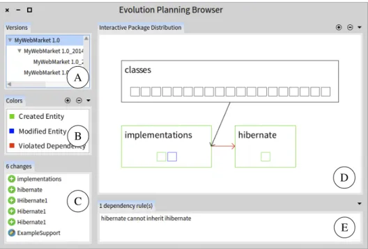
To help architects to describe systems and validate architectural constraints, we de-velopedORIONPLANNING[Santos 2015a]. ORIONPLANNINGrelies on (i) FAMIX
[Ducasse 2011], a family of meta-models to represent source code entities and re-lationships of multiple languages in a uniform way; (ii)MOOSE1for the metric
def-inition such as size, cohesion, coupling, and complexity metrics; and (iii)ORION,
a reengineering tool to simulate changes in multiple versions of the same source code model.
ORIONPLANNINGenables users to define an architecture from scratch or
itera-tively modifying a current architecture extracted from source code. Several alterna-tive versions can be explored and analysed. Our tool provides graphical representa-tions of the system at various granularity levels (package, class or method) to assist the modification of an architecture. Architecture modifications can be performed on these representations and color code enables the identification of changed enti-ties per version and per type of change.ORIONPLANNINGalso proposes an analysis
environment to check whether a given architecture (i.e., the current one or one of its various versions) is consistent with user defined restrictions. These restrictions are written as rules based on the existing metrics e.g., restricting the number of classes in a package to less than 20. Our prototype also supports the definition of dependency constraints. The definition uses the syntax ofDCL[Terra 2012], a domain specific language for conformance checking.
Figure 3.1 depicts the main user interface ofORIONPLANNING. Panel A shows
1
3.3. CONTRIBUTIONS 23 A B C D E
Figure 3.1: ORIONPLANNINGoverview.
the system under analysis and its versions, followed by a panel for color captions (Panel B), and the list of model changes in the selected version (Panel C). On the right side of the window, ORIONPLANNING provides a visualisation of model
entities and dependencies (Panel D) and a list of dependency constraints which will be evaluated when the model changes (Panel E).
3.3.2 Transformation Pattern Definition
Architecture refactoring often consists in repetitive code transformations over sev-eral components. These transformations are not mandatorily behavior preserving. Moreover, even if they are performed several times in the system, they are spe-cific to it. Concretely, they consist in a sequence of operators applied on different entities.
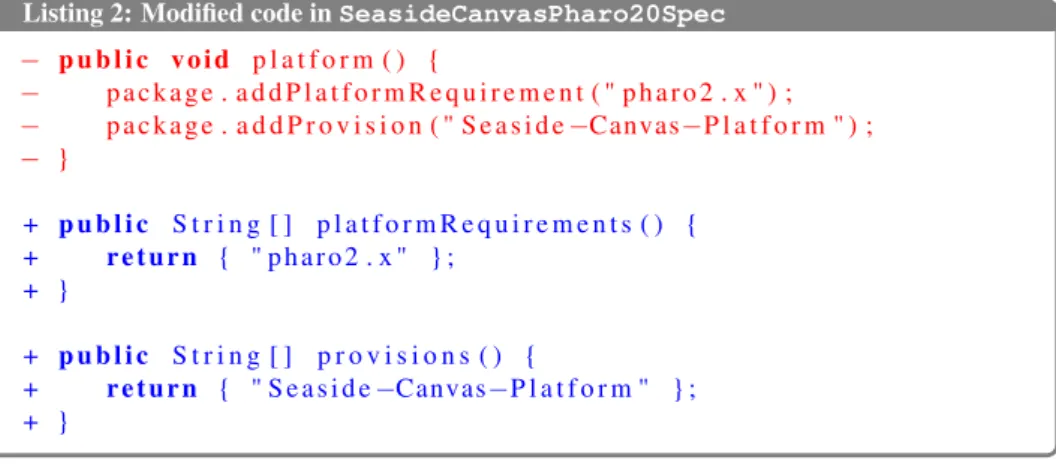
Motivating Example. Listings 1 and 2 illustrate an example of repetitive source code transformation extracted from PACKAGEMANAGER, a package management
system for PHARO2. They present code edition examples in two distinct classes,
named GreasePharo30CoreSpec and SeasideCanvasPharo20Spec. For comprehension purposes, we illustrate all the code examples in a Java-inspired
2
syntax. We also represent changed parts of source code in terms of added (+) and removed (-) lines.
Concerning the transformations involved, the developers removed a method namedplatform(). This method defines: (i) on which IDE configuration the current package depends, and (ii) the name of the package in its repository. This definition is made by invocations to the methods addPlatformRequirement
and addProvision, respectively. Instead, the developers updated this defini-tion so that each package “only provide data and do not call methods"3. In this way, the developers created two methods, named platformRequirements()
andprovisions(). Both of them return an array of strings, containing the same arguments as in the platformmethod, that is removed. This new definition is more similar to a package manifest.
Listing 1: Modified code in GreasePharo30CoreSpec − p u b l i c v o i d p l a t f o r m ( ) { − p a c k a g e . a d d P l a t f o r m R e q u i r e m e n t ( " p h a r o " ) ; − p a c k a g e . a d d P r o v i s i o n ( " G r e a s e −Core−P l a t f o r m " ) ; − } + p u b l i c S t r i n g [ ] p l a t f o r m R e q u i r e m e n t s ( ) { + r e t u r n { " p h a r o " } ; + } + p u b l i c S t r i n g [ ] p r o v i s i o n s ( ) { + r e t u r n { " G r e a s e −Core−P l a t f o r m " } ; + }
These transformations impact three methods of one class. Although these transformations seem simple, they were performed on 19 distinct classes. They are part of an architecture refactoring. Specifically, the transformations apply to all classes that extend the class PackageSpec and define a method named
platform(). Other few classes, which are responsible for deserializing the pack-age definitions, were transformed as well since the methodplatform()was re-moved. However, their updates related to this transformation are not repetitive and therefore they are not considered in this discussion.
Definition: An application condition selects, from all the entities in a system (e.g., classes, methods, etc.), which ones must be transformed.
Listing 2 shows the result of the same transformations, this time performed in the classSeasideCanvasPharo20Spec.
3
3.3. CONTRIBUTIONS 25
Listing 2: Modified code in SeasideCanvasPharo20Spec − p u b l i c v o i d p l a t f o r m ( ) { − p a c k a g e . a d d P l a t f o r m R e q u i r e m e n t ( " p h a r o 2 . x " ) ; − p a c k a g e . a d d P r o v i s i o n ( " S e a s i d e −Canvas−P l a t f o r m " ) ; − } + p u b l i c S t r i n g [ ] p l a t f o r m R e q u i r e m e n t s ( ) { + r e t u r n { " p h a r o 2 . x " } ; + } + p u b l i c S t r i n g [ ] p r o v i s i o n s ( ) { + r e t u r n { " S e a s i d e −Canvas−P l a t f o r m " } ; + }
As any algorithm, each transformation requires some specific information to be executed. For example, to perform an Add Method transformation, one must provide the signature of the method, and the class in which this method will be added. We call this information, the parameters of the transformation.
Definition: A parameter is an input, e.g, a variable or a value, that is necessary for a transformation to be executed.
Definition: The context of a set of transformations is the collection of parameters that are needed to execute its containing transformations.
Table 3.1 roughly summarises the contexts in these two examples. More specif-ically, some parameters are (i) similar in both transformations, e.g., the signatures of the (removed and added) methods are the same in Table 3.1. However, some parameters are (ii) non-identical, e.g., the return statements in Table 3.1 vary from one class to the other one. Therefore, just performing the transformations as they were defined in the first example would not produce the desired output in the sec-ond one.
Table 3.1: Context required to perform the transformations in the classes GreasePharo30CoreSpecandSeasideCanvasPharo20Spec, as presented in List-ings 1 and 2.
Transformation GreasePharo30CoreSpec SeasideCanvasPharo20Spec (as seen in Listing 1) (as seen in Listing 2)
Remove Method platform() platform()
Add Method platformRequirements() platformRequirements()
Add Return Stat. { "pharo" } { "pharo2.x" }
Add Method provisions() provisions()
Add Return Stat. {"Grease-Core-Platform"} {"Seaside-Canvas-Platform"}
Transformation Pattern Definition. Based on these definitions, we define the notion of Transformation Pattern. The term pattern comes from repetition of code
transformations.4
Definition: A transformation operator is a code transformation that can be atomic or aggregated, i.e., it considers transformations of levels one and two.
Definition: A transformation pattern is composed of (i) an application condition and (ii) a sequence of transformation operators.
The operators are ordered because they are dependent from each other [Mens 2007].
Listings 1 and 2 showed the result of the code transformations in a text based format. We represent the same example in terms of code transformations in Pat-tern 3.1. It is worth noting that the representation of PatPat-tern 3.1 is purely to under-stand the transformations that took place. Transformation patterns are not repre-sented like this in our approach.
PATTERN 3.1: PACKAGEMANAGER’s transformation pattern.
Description:Correcting package platform definition Applied to:19 classes.
Condition:∃ class C that extends PackageSpec and ∃ method M in C named “platform” 1. Add Method M’ named “platformRequirements” in C
2. Add Return Statement in M’ with an array containing:
the argument of the invocation to “addPlatformRequirement” in M 3. Add Method M” named “provisions” in C
4. Add Return Statement in M” with an array containing: the argument of the invocation to “addProvision” in M 5. Remove Method M
In this pattern, each step (lines 1 to 5) consists in a transformation operator. These transformations are exactly the ones presented in Table 3.1. The application condition specifies that this transformation pattern shall be applied to all of the classes extendingPackageSpecwhich implement a method namedplatform(). Moreover, each transformation operator requires some parameters to be assigned, e.g., classC. We provided examples of the context of the transformation pattern as shown in Table 3.1.
3.3.3 Relevance of Transformation Patterns
We propose research questions to discuss the importance of automated support in the application of transformation patterns. We restrict our study to system specific code transformations. We presented one example of transformation pattern in the 4From Merriam-Webster dictionary, the regular and repeated way in which something happens or is done[dic ].
3.3. CONTRIBUTIONS 27 previous section. Although there are evidences in the literature of the existence of such transformations [Nguyen 2010, Ray 2012, Nguyen 2013], there is a lack of approaches that provide support for composite, system specific transformations. Considering this specific context, we propose a main research question:
RQ1 Can we identify instances of (system specific) transformation patterns in other systems?
Assessing Transformation Patterns. We propose RQ1 to demonstrate the gen-erality of the problem. To complement this research question, we also evaluate potential properties of the transformation patterns that motivate some automated support in their application. Note that we will not further formalise our research questions (formal hypothesis) or formally test them. All that is required in this study is proof of existence in various systems. We describe the complementary research questions as follows.
CRQ1 Are transformation patterns applied to all of the transformation opportu-nities? For each application condition, we investigate whether the corre-sponding transformation pattern was applied to all of the code entities it was supposed to.
CRQ2 Are transformation patterns applied accurately in each code location? Given that a transformation pattern is a sequence of operators, we investi-gate whether all of the operators were performed in each occurrence of the pattern.
CRQ3 Are transformation patterns applied over several revisions of the system? We investigate whether the patterns were applied at once or over several revisions.
These research questions were evaluated on four Java programs: ECLIPSE,
JHOTDRAW,MYWEBMARKETandVERVEINEJ; and five Pharo systems that under-went a restructuring effort in our research group: PETITSQL,PETITDELPHI,PACK
-AGEMANAGER, TELESCOPE and GENETICALGORITHM [Santos 2015c]. Table 3.2
gathers the values for the metrics relative to the different research questions. TELE
-SCOPEandGENETICALGORITHMfor which no pattern was identified do not appear
in the table.
Target Systems (RQ1) We identified transformation patterns in seven out of nine systems. These systems use two different programming languages (Java and Pharo), and our study analyzed only one specific version of each system, related to their rearchitecting. We identified more than one pattern in two systems.
Are transformation patterns applied to all of the transformation opportunities? (CRQ1) Three out of eleven transformation patterns were not applied to all the
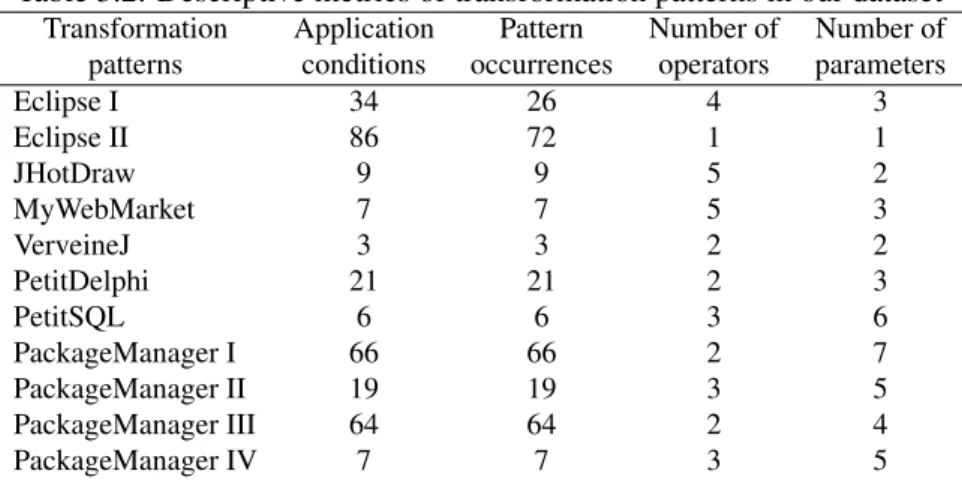
Table 3.2: Descriptive metrics of transformation patterns in our dataset
Transformation Application Pattern Number of Number of patterns conditions occurrences operators parameters
Eclipse I 34 26 4 3 Eclipse II 86 72 1 1 JHotDraw 9 9 5 2 MyWebMarket 7 7 5 3 VerveineJ 3 3 2 2 PetitDelphi 21 21 2 3 PetitSQL 6 6 3 6 PackageManager I 66 66 2 7 PackageManager II 19 19 3 5 PackageManager III 64 64 2 4 PackageManager IV 7 7 3 5
opportunities matching the application condition. When the patterns covered all the opportunities, this fact was due to their low frequency, or because the pattern consisted of a systematic and corrective task.
Are transformation patterns applied accurately in each code location? (CRQ2)In one out of eleven transformation patterns, not all of their transformation operators were performed in some occurrences. This fact does not seem to be correlated with the number of transformation operators, neither with the number of occurrences of the pattern.
Are transformation patterns applied over several revisions of the system? (CRQ3) Two out of eleven transformation patterns were applied in several revisions. This fact might be related to the perfective maintenance nature of their transformations, i.e., not applying the transformation pattern in all the occurrences did not seem to have impact on these systems.
3.3.4 Automating Transformation Pattern Application
Transformation patterns may be complex and possibly applied in a lot of different occurrences. The previous evaluation highlighted that some occurrences were in-complete, completely missing, or identified through several later revisions. To ease the application of transformation patterns, we provide an automated support.
MACRORECORDER has been developed to record, configure, and replay
trans-formation patterns [Santos 2015b]. Using our approach in practice, the developer manually performs the changes once. The tool collects and stores these changes. The developer then specifies a different code location in which MACRORECOR
3.4. PERSPECTIVES 29 into a customised transformation that would be instantiated in the specified loca-tion and automatically configure it. In some cases, this generalisaloca-tion has to be manually edited or performed. Finally, the tool searches for fragments of source code that match the customised transformation specified in the previous stage. If successful, the tool instantiates the transformation into these code entities and per-forms the transformation automatically.
The current implementation of the tool is developed inPHARO. It relies on the
following requirements:
• a code change recorder. The recorder is an extension of an IDE (e.g.,ECLIPSE,
EPICEAforPHARO) which is responsible for monitoring activity edition and
storing code changes through operators;
• an IDE supporting source code entities inspection and automatic manipula-tion of their underlying code (for parameter automatic configuramanipula-tion); • a code transformation tool (e.g., ECLIPSE’s refactoring tools, REFACTORING
inPHARO). The transformation tool will be extended to provide replication
of each recorded code change event.
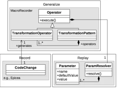
MACRORECORDER relies on an abstract representation of the code and on a
change metamodel. Figure 3.2 presents an overview of the proposed approach (highlighted in grey). The transformation operator establishes the connection be-tween recorded code change events in EPICEA and code edition algorithms in the
transformation tool (through ParamResolver that resolves parameters). A transfor-mation pattern is a special type of operator that contains (and eventually executes) a collection of transformation operators.
This work is realised in the context of Gustavo Santos PhD thesis that I co-supervise with Dr Nicolas Anquetil and within a collaboration with Professor Marco Tulio Valente from Universidade Federal de Minas Gerais, Brazil.
3.4
Perspectives
Back to Code. ORIONPLANNINGenables the architect to modify software
archi-tectures on a large scale based on graphical representations and constraint verifica-tions. Several alternatives can be explored and analyzed. Currently, modifications occurring on the abstract representation of the software have to be manually ap-plied on the code. However we believe that such manual activity is tedious and error prone. The goal is to generate code snippets, following the assumption that the architecture might not be fully described. The snippets would have enough information for developers to further complete them. An important improvement would be to include Abstract Syntax Tree (AST) modeling toORIONPLANNING, in
Figure 3.2: Overview ofMACRORECORDERapproach
This representation opens new research perspectives such as the opportunity to tackle language transformations, for example to switch from Java to Pharo. Para-digm changes such as from Cobol to Java would be managed later when transfor-mation inside the same family of languages is mastered.
On the other hand, the introduction of an AST representation of the code will largely increase already very big models. Scalability issues have to be foreseen. A solution could be to have access to this finer representation on demand. It also raises new issues since rearchitecting is often performed on abstract system rep-resentations without taking into account fine grained information contained in the code.
Automating Transformation Pattern Application. With only one or two exam-ples of the pattern application its is hard or even impossible to deduce the appli-cation condition. Consequently, the developer has to select new loappli-cation, before the parameters are automatically matched and the transformation pattern applied again. Selecting one by one these new locations can be tedious for example when they are 72 as in one of the studied example. An alternative is to manually spec-ify the application condition to enable a wide application on the whole system. Deducing or tuning the application condition would help in the diffusion of such tool.
![Figure 2.3: Approach Process Overview (copied from [Aranega 2012]) This approach relies on three pillars: (i) the classification of the available trans-formations as a Feature Diagram (FD) produced by the business expert 7 , (ii) the](https://thumb-eu.123doks.com/thumbv2/123doknet/2478583.50258/21.892.139.681.613.934/approach-process-overview-aranega-classification-available-formations-business.webp)