HAL Id: hal-02458493
https://hal.archives-ouvertes.fr/hal-02458493
Submitted on 26 May 2020HAL is a multi-disciplinary open access
archive for the deposit and dissemination of sci-entific research documents, whether they are pub-lished or not. The documents may come from teaching and research institutions in France or abroad, or from public or private research centers.
L’archive ouverte pluridisciplinaire HAL, est destinée au dépôt et à la diffusion de documents scientifiques de niveau recherche, publiés ou non, émanant des établissements d’enseignement et de recherche français ou étrangers, des laboratoires publics ou privés.
Carbon Nanotube/Cellulose Nanocrystal Hybrid
Conducting Thin Films
Christophe Olivier, Jean Bruno Mougel, Patricia Bertoncini, Céline Moreau,
Isabelle Capron, Bernard Cathala, Olivier Chauvet
To cite this version:
Christophe Olivier, Jean Bruno Mougel, Patricia Bertoncini, Céline Moreau, Isabelle Capron, et al.. Carbon Nanotube/Cellulose Nanocrystal Hybrid Conducting Thin Films. Journal of Renewable Ma-terials, Scrivener publishing, 2018, 6 (3), pp.237-241. �10.7569/JRM.2017.634168�. �hal-02458493�
*Corresponding author: olivier.chauvet@cnrs-imn.fr
DOI: 10.7569/JRM.2017.634168
Thin Films
Christophe Olivier1,2, Jean Bruno Mougel1,2, Patricia Bertoncini1, Celine Moreau2, Isabelle Capron2,
Bernard Cathala2 and Olivier Chauvet1*
1Jean Rouxel Institute of Materials (IMN), University of Nantes, CNRS, 2 rue de la Houssinière BP32229, 44322 Nantes cedex 3, France 2BIA, INRA, 44300 Nantes, France
Received May 19, 2017; Accepted September 25, 2017
ABSTRACT: Cellulose nanocrystals (CNCs) have a high ability to disperse single-walled carbon nanotubes (SWNTs) in aqueous media and to form hybrids. These hybrids are used to grow layer-by-layer thin films of controlled thickness. Thanks to the presence of SWNTs, these films are conducting. In this article, we describe the process by which the CNC/SWNT hybrids are obtained and discuss the electrical properties of the hybrid-based layer-by-layer films.
KEYWORDS: Nanocellulose, nanotube, LbL thin films, hybrids
1 INTRODUCTION
Cellulose is one of the most abundant renewable resources on Earth and its use has been the subject of intensive research for centuries. Cellulose consists of linear homopolymer chains of glucose unit linked by β(1-4) linkages that interact strongly by hydrogen bonds and van der Waals interaction to form cellulose microfibrils. For several decades, disruption of cel-lulose microfibrils down to nanoscale has opened up tremendous opportunities to generate amazing mate-rials termed nanocellulose that can be divided into two main families: cellulose nanofibrils (CNFs) and cellulose nanocrystals (CNCs). CNCs are stiff crystal-line nanorods obtained by harsh acid hydrolysis [1], which are now industrially available materials. They have been used in a very wide range of applications such as fillers for nanocomposites, surface active agents for emulsions, self-assembling materials dis-playing optical properties, coatings, and many oth-ers [2–4]. Thanks to their colloidal properties arising from their nanometric dimensions and the presence of charges on their surface that induce electrostatic repul-sions, CNCs have also been used as dispersing agents. They have been efficiently used for dispersing carbon nanotubes, leading to hybrid nanoparticles achieving
very high yields of dispersion [5]. The precise asso-ciation mechanism is still not fully understood but it has been proposed to arise either from entropic gain due to association of hydrophobic planes of CNCs and nanotube surface [6] or from polarization of nano-tubes due to the highly charged nanocellulose surface [7]. Nevertheless, highly stable hybrid nanoobjects are obtained when nanotubes and nanocellulose are combined. These objects are of great interest for the elaboration of strong and conductive composites. For instance, incorporation of multiwalled carbon nanotubes associated with CNFs has been imple-mented in mechanosensitive aerogels, mechanically strong and conductive nanopapers and microfibers [8–9]. Nanotube/nanocellulose hybrids also display another feature that can be used for the elaboration of materials. Indeed, thanks to the fabrication process, both CNFs and CNCs bear anionic charges on their surfaces. In the case of CNFs for instance, carboxylic groups can be introduced prior to the separation of nanofibers by TEMPO oxidation [10]. In the case of CNCs, sulfate half-ester groups are introduced dur-ing acid hydrolysis when sulfuric acid is used [11]. The presence of these charges can be used for building multilayered structure through the layer-by-layer pro-cedure (LbL). LbL is a generic technique that allows the assembly of polymers or nanoparticles, present-ing attractive interactions such as oppositely charge polyelectrolytes [12]. It has been widely applied to polymers but also to nanoparticles including nanocel-lulose [13–15]. This technique has also been used to
Olivier Chauvet et al.: Carbon Nanotube/Cellulose Nanocrystal Hybrid Conducting Thin Films DOI: 10.7569/JRM.2017.634168
build nanocarbon/nanocellulose multilayered films [6]. In our previous work [6], we reported the disper-sion of single-walled carbon nanotubes (SWNTs) by CNCs and the efficient use of SWNT/CNC hybrids for the elaboration of conductive and luminescent thin films through the LbL technique. Here, we first detail how the dispersion process of SWNTs by CNCs can be described and predicted by a kinetic model. Then, we show that hybrids can be used for the elaboration of conductive films and that their electrical properties can be tuned by adjusting the amount and the position of hybrid nanoparticle layers in the film.
2 SWNT/CNC HYBRIDS
2.1 Cellulose Nanocrystals Preparation
The preparation of CNCs has been performed accord-ing to the procedure of Revol et al. [11], as described earlier [5]. Briefly, the CNCs are obtained from cot-ton linters after sulfuric acid hydrolysis. The mixture is repeatedly washed and centrifuged until a stable colloidal suspension is obtained. The colloidal sta-bility comes from repulsive electrostatic interactions between the cellulose nanorods due to negatively charged sulfate half-ester groups grafted onto the sur-face after the hydrolysis step. Transmission electron microscopy measurements have shown that the CNCs are 130 nm long on average and have lateral dimen-sions between 6 and 10 nm.2.2 SWNT/CNC Hybrid Dispersions
Carbon nanotubes are difficult to disperse in aqueous media because of the hydrophobic carbon surface. CNCs have the ability to quite efficiently disperse carbon nanotubes [6, 7]. SWNTs (Unidym, batch P0261) are added to a CNC suspension of a given concentration and dispersed by using cup horn sonication (20 kHz, sonication power 0.7 W/mL). Sonication is followed by centrifugation at 20,000 g during 30 min in order to precipitate non-dispersed SWNTs.2.3 Characterization
In a previous study [5], we investigated the effect of different parameters on the dispersion process and identified the experimental conditions that lead to the maximum yield. The yield is defined as Y = [SWNT]
final/[SWNT]initial where [SWNT]final and [SWNT]initial
represent the SWNT concentration after and before the whole dispersion process, respectively. [SWNT]
final is deduced from optical absorption [5]. It is found
that the yield depends on the sonication time and is limited by the initial concentration of both CNCs and SWNTs. Figure 1 shows the evolution of the yield with the sonication time when [SWNT]initial = 0.5 g/L is mixed with a suspension of CNCs concentrated at 4 g/L ([CNC]=4g/L). The time evolution follows a unimolecular rate law shown as a continuous line in Figure 1:
Y = Y0 × [1−exp(−t/t)]
(1)
where Y0 = 51% and t = 109 min.
The time constant t does not depend on the
ini-tial concentrations of CNCs and SWNTs contrary to
Y0. The unimolecular rate law of Equation 1 suggests that the dispersion yield is controlled by a simple association mechanism. It leads to a “stoichiometric” relationship, as demonstrated in reference [5], with a maximum yield Y0 related to [CNC] and [SWNT] by:
Y0 = 0.005 × [CNC]/[SWNT]initial (2) In reference [5] it is shown that this specific stoi-chiometry is directly related to the morphology of the hybrids. The dispersion process leads to CNCs aligned along the SWNTs, one CNC being found every ~ 330 nm of SWNT on average.
Such association results in a very good control of the dispersion of SWNTs in aqueous media with a con-stant CNC/SWNT ratio. It is then possible to consider all applications where CNC has a templating impact and where electrical conductivity is required. This is the case for thin films since mechanical, optical and electric properties may be reached simultaneously by using these hybrid nanoparticles.
0 0 10 20 30 40 50 60 50 100 150 Sonication time (mn) Yield (%) 200 250
Figure 1 Evolution of the yield of the dispersion process
versus the sonication time (initial parameters: ultrasound power 0.7 W/mL, [CNC] = 4 g/L, [SWNT] = 0.5 g/L). The continuous line fits the data with a unimolecular rate law described in the text.
3 FILM ELABORATION
Multilayer thin films are obtained by layer-by-layer (LbL) assembly. This approach is based on the alter-nate adsorption of oppositely charged polyelectro-lytes [12]. As shown by Kotov et al. [16], the negatively charged CNCs may interact with polyanions to form LbL thin films. In this work, poly(allylamine hydro-chloride) (PAH, Sigma-Aldrich) is used as polyca-tionic layer. The anionic layer is obtained from hybrid aqueous dispersion containing CNCs at 20 g/L and by adjusting the final SWNT content to vary the ratio R, defined as R = [SWNT]/[CNC], between 0 and 13%. A dipping procedure is used to deposit the films on glass substrates. The details of the procedure are given in [6, 15]. Briefly, the prepared substrate is dipped into a 4 g/L PAH solution in a MES buffer with or without 1M NaCl for 1 min. It is then rinsed 3 times in water and dried under nitrogen flux. Finally the substrate is dipped again for 1 min in the hybrid dispersion, rinsed and dried again. This procedure allows build-ing one PAH-hybrid bilayer. It is cycled n times to build n-bilayer thin films. This LbL dipping process allows elaborating very nice uniform films, as demon-strated by their color with enzyme-sensing properties, for example [13].
The thickness of the films is measured with a Veeco Dektak 8 profilometer. As shown in Figure 2, the growth of the LbL films is very regular with a thick-ness directly proportional to the number of bilayers.
When 1M NaCl is added in the PAH solution, the films grow with a thickness of 16.5 nm/bilayer. This thickness does not depend on the SWNT con-centration in our R range (R < 13%). Indeed, Raman
scattering spectroscopy shows that the nanotubes do not desorb during the dipping process [5]. When no salt is added to the PAH solution, the films grow thin-ner with a thickness of 8.8 nm/bilayer. This difference is attributed to the effect of the ionic strength on the PAH conformation. In the absence of ionic strength, as a polyelectrolyte, the PAH chains have an extended chain configuration. The adsorption of CNC hybrids occurs directly on the PAH layer. It is worth noting that the thickness of the CNC hybrid layer is close to the thickness of a CNC itself (between 6 to 10 nm). It sug-gests that in the absence of ionic strength, a single layer of CNC hybrids is deposited every cycle (the thickness of the PAH layer is smaller than 1 nm). When the ionic strength is high, the PAH adopts a coiled conforma-tion. It leads to an adsorption of the CNC hybrid layer which is twice as thick. It suggests that a double layer of CNC hybrids has been deposited instead of a single layer, as observed for raw CNCs [15]. Modulating the ionic strength of the PAH solution allows modulating the thickness and the architecture of the LbL thin films.
4 ELECTRICAL PROPERTIES
The PAH and cellulose are insulating polymers while one third of the SWNTs are conducting. Figure 3 pre-sents scanning electron microscopy (SEM) micrographs of an 8-bilayer film with R = 2%. The micrograph in the right panel has been obtained after sputtered gold metallization (standard procedure for insulat-ing surface), while the micrograph in the left panel has been obtained without metallization. The fact that it is possible to observe an image without metalliza-tion shows that the film is electrically conducting. The micrographs clearly exhibit different morphologies. The CNCs are revealed after the metallization pro-cedure while the SWNTs are easily observed on the sample without metallization. As expected, there is no
1 0 20 60 80 100 120 140 40 2 3 4 5 6 7 8 Number of bilayers Thickness (nm)
Figure 2 Thickness of the thin films versus number of
deposited bilayers (R = 2%). The black diamonds show the growth in the presence of 1M NaCl, the white diamonds correspond to the films obtained without NaCl. The straight lines give an average thickness of 16.5 nm/bilayer and 8.8 nm/bilayer with or without salt respectively.
1 µm 1 µm
Figure 3 SEM micrographs without (left) and with (right)
metallization of an 8-bilayer film (16.5 nm/bilayer, R = 2%). The CNCs are clearly visible as rigid rods after the metallization step, while the SWNTs are visible without the metallization thanks to their conducting properties (entangled bright structures).
Olivier Chauvet et al.: Carbon Nanotube/Cellulose Nanocrystal Hybrid Conducting Thin Films DOI: 10.7569/JRM.2017.634168
preferential orientation of the SWNTs and the CNCs in the plane. It can also be seen that there is a signifi-cant entanglement of the SWNTs, which may favor the electrical contacts between SWNTs.
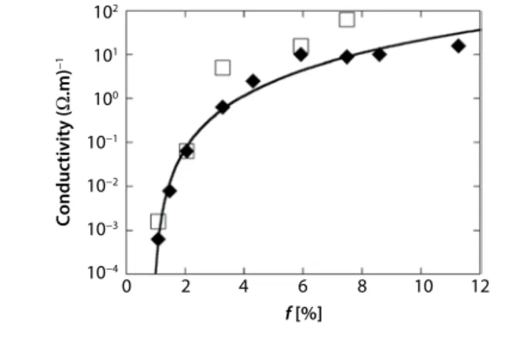
In order to probe the electrical properties of the films, gold electrodes are sputtered on the films and the conductivity is measured in the 4-point probe con-figuration, in the ohmic regime at room temperature. The relative humidity is set at 57%. The results for sev-eral 8-bilayer films are shown in Figure 4, where the (mass) fraction of SWNT in the film is defined as f =
R/(1+R). The black diamonds correspond to
measure-ments on CNC hybrid 16.5 nm/bilayer films while the white squares correspond to hybrid 8.8 nm/bilayer films. As shown in Figure 1, the 8-bilayer films pre-pared with and without NaCl have a thickness of about 132 nm and 65 nm respectively.
Let us first discuss the case of 16.5 nm/bilayer films. When loaded with f > 3%, the films are conduct-ing with a conductivity level of more than 1 (Ω.m)–1.
The electrical conductivity is indeed strongly dependent on the fraction of SWNTs. It increases from 6.10–4 (Ω.m)–1 to 15 (Ω.m)–1 when f varies between 1%
to 12%. This nonlinear increase of the conductivity is attributed to the percolation of the SWNT network throughout the films. As shown as the continuous line in Figure 4, the evolution of the conductivity σ with f obeys the percolation power law equation (Eq. 3).
s s b = × − − 0 1 f f f c c (3) The critical mass fraction threshold is fc ≈ 0.9% and is comparable to that found in SWNT compos-ites with synthetic polymers. Such small values arise
from the high aspect ratio of the conducting fillers, the lowest threshold having the best dispersion in the matrix. The critical conductivity exponent is found to be b ≈ 2.71, very close to 2.18, i.e., the expected value
for percolation at 3D [17]. This suggests that the con-duction pathway is three-dimensional (3D) and not two-dimensional (2D). The prefactor is found to be
s0 ≈ 1.4.104 (Ωm)–1. This value corresponds to the
con-ductivity of the SWNTs network alone if the critical power law is obeyed for all f, i.e., 0 < f < 1, which is usually not the case. This value is high but smaller by one order of magnitude than that found in synthetic composites.
One may expect a 2D conducting mechanism since the films are built by a layer-by-layer process. As already mentioned, the critical exponent of the con-ductivity is not in agreement with a 2D conducting pathway. Another way to check the dimensionality of the conduction mechanism is to try to bury the con-ducting hybrid layer within the film. The 8-bilayer films have been prepared with only one bilayer built with hybrids (f = 11.2%), the 7 other ones being built with CNCs alone in the presence of 1M NaCL. This “conducting layer” is positioned from bilayer n°1 (the closest to the substrate) to n°8 (the top bilayer). The conductivity of the film is measured and nor-malized to the actual thickness of the conducting layer (16.5 nm) instead of the whole film (132 nm). The results for the 5 top layers are shown in Figure 5. The conductivity of the “fully conducting” 8-bilayer film (f = 11.2%) is close to 15 (Ω.m)-1. Figure 5 shows
two things. First, the conductivity of a single hybrid bilayer is very close to the conductivity of the whole film when the “conducting bilayer” is buried at the top or 2 bilayers away from the top (at least 33 nm
2 4 6 8 10 12 0 10−4 10−3 10−2 10−1 100 101 102 f [%] Conductivity (Ω .m) −1
Figure 4 Conductivity of 8-bilayer films versus the fraction
f of SWNTs. The black diamonds show the 16.5 nm/bilayer
thick films (built in the presence of salt) and the white squares the 8.8 nm/bilayer thick one, respectively. The continuous line shows the fit of the black diamonds with a percolation law as discussed in the text.
4 5 6 7 8 10−4 10−5 10−6 10−3 10−2 10−1 100 101 Layer number Conductivity (Ω .m) −1
Figure 5 Conductivity of an 8-bilayer film (16.5 nm/bilayer)
when only the numbered bilayer is composed of SWNT/ CNC hybrids (f = 11.2%), the other ones being without SWNTs. Layer number 1 is at the bottom and layer number 8 is the top layer.
from the surface). Secondly, the conductivity of the film remains quite noticeable. This point indeed sug-gests that at least a part of the nanotubes may emerge from the hybrid bilayer and probably cross-insulat-ing top bilayers to give access to the surface. It means that even if conduction is preferentially 2D, 3D con-nections should occur with a conduction occurring in the bulk of the film.
Let us come back to the 8.8 nm/bilayer films (white squares of Figure 4). The conductivity of these films seems to be slightly higher than that of the 16.5 nm/ bilayer one. It is likely due to an enhancement of the transverse conduction across the PAH layer due to denser organization.
5 CONCLUSION
In summary, dispersions of noncovalently func-tionalized SWNTs by CNCs were obtained using a sonication method that preserves the electronic properties of the SWNTs. The yield of the disper-sion process is fixed by the experimental prepara-tion condiprepara-tions. The study reveals not only that the hybrids can be used to build LbL films by alternat-ing layers of PAH and SWNT/CNC hybrids but also that the films have a controlled thickness and all exhibit conducting properties. CNCs can be func-tionalized and bioconjugated with many molecules, offering the opportunity to build LbL films with new functionalities.
REFERENCES
1. Y. Habibi, L.A. Lucia, and O. Rojas, Cellulose nanocrys-tals: Chemistry, self-assembly, and applications. Chem.
Rev. 110, 3479–3500 (2010).
2. D. Klemm, F. Kramer, S. Moritz, T. Lindstrom, M. Ankerfors, D. Gray, et al., Nanocelluloses: A new fam-ily of nature-based materials. Angew. Chem. Int. Ed. 50, 5438–5466 (2001).
3. R.J. Moon, A. Martini, J. Nairn, J. Simonsen, and J. Youngblood, Cellulose nanomaterials review: Structure, properties and nanocomposites. Chem. Soc.
Rev. 40, 3941–3994 (2011).
4. C. Moreau, A. Villares, I. Capron, and B. Cathala, Tuning supramolecular interactions of cellulose nanocrystals todesign innovative functional materials.
Ind. Crops Prod. 93, 96–107 (2016).
5. J.B. Mougel, C. Adda, P. Bertoncini, I. Capron, B. Cathala, and O. Chauvet, Highly efficient and pre-dictable noncovalent dispersion of single-walled and multi-walled carbon nanotubes by cellulose nanocry-stals. J. Phys. Chem. C 120, 22694–22701 (2016).
6. C. Olivier, C. Moreau, P. Bertoncini, H. Bizot, O. Chauvet, and B. Cathala, Cellulose nanocrystal-assisted dispersion of luminescent single-walled car-bon nanotubes for layer-by-layer assembled hybrid thin films. Langmuir 28, 12463–12471 (2012).
7. A. Hajian, B. Lindström, T. Pettersson, M. Hamedi, and L. Wågberg, Understanding the dispersive action of nanocellulose for carbon nanomaterials. Nano Lett. 17, 1439–1447 (2017).
8. M.M. Hamedi, A. Hajian, A.B. Fall, K. Hakansson, M. Salajkova, F. Lundell, L. Wagberg, and L.A. Berglund, Highly conducting, strong nanocomposites based on nanocellulose-assisted aqueous dispersions of single-wall carbon nanotubes. ACS Nano 8, 2467–2476 (2014). 9. M. Wang, I.V. Anoshkin, A.G Nasibulin, J.T. Korhonen,
J. Seitsonen, J. Pere, E.I. Kauppinen, R.H. Ras, and O. Ikkala, Modifying native nanocellulose aerogels with carbon nanotubes for mechanoresponsive conductivity and pressure sensing. Adv. Mater. 25, 2428–2432 (2013). 10. Y. Habibi, Key advances in the chemical modification of nanocelluloses. Chem. Soc. Rev. 43, 1519–1542 (2014). 11. J.F. Revol, H. Bradford, J. Giasson, R.H. Marchessault,
and D.G. Gray, Helicoidal self-ordering of cellu-lose microfibrils in aqueous suspension. Int. J. Biol.
Macromolec. 14, 170–172 (1992).
12. G. Decher, J.D. Hong, and J. Schmitt, Buildup of ultrathin multilayer films by a self-assembly process: III. Consecutively alternating adsorption of anionic and cationic polyelectrolytes on charged surfaces. Thin
Solid Films 210, 831–835 (1992).
13. C. Cerclier, A. Lack-Guyomard, C. Moreau, F. Cousin, N. Beury, E. Bonnin, B. Jean, and B. Cathala, Coloured semi-reflective thin films for biomass-hydrolyzing enzyme detection. Adv. Mater. 23, 3791–3795 (2011). 14. C. Martin, and B. Jean, Nanocellulose/polymer
multilay-ered thin films: Tunable architectures towards tailored physical properties. Nord. Pulp Pap. Res. J. 1, 19–30 (2014). 15. C. Moreau, N. Beury, N. Delorme, and B. Cathala,
Tuning the architecture of cellulose nanocrystal– poly(allylamine hydrochloride) multilayered thin films: Influence of dipping parameters. Langmuir 28, 10425–10436 (2012).
16. N.A. Kotov, I. Dekany, J.H. Fendler, Layer-by-layer self-assembly of polyelectrolyte-semiconductor nanoparticle composite films. J. Phys. Chem. 99, 13065–13069 (1995). 17. D. Stauffer and A. Aharony, Introduction to Percolation
![Figure 1 Evolution of the yield of the dispersion process versus the sonication time (initial parameters: ultrasound power 0.7 W/mL, [CNC] = 4 g/L, [SWNT] = 0.5 g/L)](https://thumb-eu.123doks.com/thumbv2/123doknet/11500619.293615/3.981.520.907.125.380/figure-evolution-dispersion-process-sonication-initial-parameters-ultrasound.webp)