MODELING AND CONTROL OF A FLEXIBLE SPACE ROBOT TO CAPTURE A TUMBLING DEBRIS
VINCENT DUBANCHET
DÉPARTEMENT DE GÉNIE ÉLECTRIQUE ÉCOLE POLYTECHNIQUE DE MONTRÉAL
THÈSE PRÉSENTÉE EN VUE DE L’OBTENTION DU DIPLÔME DE PHILOSOPHIÆ DOCTOR
(GÉNIE ÉLECTRIQUE) OCTOBRE 2016
c
UNIVERSITÉ DE MONTRÉAL
ÉCOLE POLYTECHNIQUE DE MONTRÉAL
Cette thèse intitulée:
MODELING AND CONTROL OF A FLEXIBLE SPACE ROBOT TO CAPTURE A TUMBLING DEBRIS
présentée par: DUBANCHET Vincent
en vue de l’obtention du diplôme de: Philosophiæ Doctor a été dûment acceptée par le jury d’examen constitué de:
M. GOURDEAU Richard, Ph. D., président
M. SAUSSIÉ David, Ph. D., membre et directeur de recherche
Mme BÉRARD Caroline, Doctorat, membre et codirectrice de recherche M. ALAZARD Daniel, H.D.R., membre et codirecteur de recherche Mme AKHRIF Ouassima, Ph. D., membre
DEDICATION
iv
ACKNOWLEDGEMENTS
This co-thesis was performed between the École Polytechnique of Montreal and the French engineering school ISAE-Supaéro at Toulouse, at the crossroads of two distinct educational system. Beyond the technical and teaching excellence of my teachers, their moral support and their constant help were crucial to succeed in such a project. I would like to thank as warmly and sincerely as possible David Saussié at Montreal, as well as Daniel Alazard and Caroline Bérard at Toulouse. In this long journey, you managed to guide me, to push me and to motivate me to always give the best of myself during all my researches and through my writing. It was a real chance to count you as my supervisors and if I had to start again, it would be with the same enthusiasm!
Nevertheless, the Ph.D. degree is not solely based on the work provided, but, above all, on the evaluation and endorsement of experts in the field. I am therefore extremely grateful to the external members of my jury: Richard Gourdeau, Ouassima Akhrif and Samir Bennani. I would like to insist that I was deeply honored that they accepted to report on my thesis. I thank them for taking the time and the care to evaluate my work, and for having provided so many ways of improvement and constructive comments for the future.
I would also like to thank Thales Alenia Space for co-funding this project and for allowing me to validate my results on their robotic test bench during six months. More precisely, I thank Catherine Le Peuvédic for her coaching throughout the thesis, as well as Adrien Grynagier, Xavier Roser and Carole Billot for their help during my internships in Cannes.
This thesis also received a valuable support from the France-Quebec scholarship Frontenac, to promote the mobility of Ph.D. students involved in a co-thesis. This grant allowed to fund one working stay per year in Montreal during the three years of the project, as well as the trip of David Saussié for the thesis defense in Toulouse.
Now, I want to come back to the people I met in the two schools, both for working purposes or during my many administrative issues.
In Montreal, I would like to express my sincere friendship to my former supervisor Lahcen Saydy for all his life advices, to Suzanne Le Bel for her culinary gifts, to Marc Charbonneau for his good mood, and to Nathalie Lévesque for her kindness and constant help. I cannot forget the work atmosphere of the laboratory, so inspiring thanks to all my colleagues from
all over the world: with Alexandre, Caroline, Antoine, Hugo, Lyes, Rabih, Meisam, Saad, Kai-Jun. . . , and with all the trainees including Florian, Benoit and Camille, to name but a few. In the same way, I had the chance to meet extremely warm colleagues during my internships at Thales with Carole, François and Francois, Juhaina, Hugues, Benoit, Quentin, Marie, Sabrina, Lorenzo and Francis. Finally, the end of my thesis in Toulouse was greatly enlivened and brightened by Régine Leconte, Stéphanie Lizy-Destrez and Bénédicte Escudier, as well as Françoise Loytier, Marie Fauré, Thierry Duigou, Alain Bouinot and Etienne Perrin. Similarly, I cannot forget my last “academic” colleagues with these technical or philosophical debates while playing some darts with Yann, Emilien and Fabien.
Before concluding, I would like to mention the closest friends I had during these last years, to tell them once again my deepest gratitude and sincere friendship for the good times and, above all, for the shoulder they offered me in the most difficult moments. A huge “Thank you” to Toto, Tilda, Laure, Phil and Ben in Montreal, to Emilien, Geoffrey, Bastien and Valentin in Toulouse, and finally to Angie to thank her for giving me so much love and motivation all along the road.
I finally dedicate this degree and these years of hard work to all my beloved family. Some people think that science is built "on the shoulders of giants", but I truly believe that I re-lied much more upon those of my family during this thesis. . . The love of my parents, of my brother, of my grandparents and of all my uncles and aunts had nurtured my efforts until the end and had given me the strength to make this great challenge successful.
Without the contribution of all these people, this step of my life would have never had the same flavor and I would not have thriven so much . . . Thanks for everything!
vi
RÉSUMÉ
La conquête spatiale des 60 dernières années a généré une grande quantité d’objets à la dé-rive sur les orbites terrestres. Leur nombre grandissant constitue un danger omniprésent pour l’exploitation des satellites, et requiert aujourd’hui une intervention humaine pour réduire les risques de collision. En effet, l’estimation de leur croissance sur un horizon de 200 ans, connue sous le nom de “syndrôme de Kessler”, montre que l’accès à l’Espace sera grandement menacé si aucune mesure n’est prise pour endiguer cette prolifération. Le scientifique J.-C. Liou de la National Aeronautics and Space Administration (NASA) a montré que la tendance actuelle pourrait être stabilisée, voire inversée, si au moins cinq débris massifs étaient désor-bités par an, tels que des satellites en fin de vie ou des étages supérieurs de lanceur. Parmi les nombreux concepts proposés pour cette mission, la robotique s’est imposée comme une des solutions les plus prometteuses grâce aux retours d’expérience des 30 dernières années. La Station Spatiale Internationale (ISS) possède déjà plusieurs bras robotiques opérationnels, et de nombreuses missions ont démontré le potentiel d’un tel système embarqué sur un satellite. Pour deux d’entre elles, des étapes fondamentales ont été validées pour le service en orbite, et s’avèrent être similaires aux problématiques de la désorbitation des débris.
Cette thèse se concentre sur l’étape de capture d’un débris en rotation par un bras robo-tique ayant des segments flexibles. Cette phase comprend la planification de trajectoire et le contrôle du robot spatial, afin de saisir le point cible du débris de la façon la plus délicate possible. La validation des technologies nécessaires à un tel projet est quasiment impossible sur Terre, et requiert des moyens démesurés pour effectuer des essais en orbite. Par consé-quent, la modélisation et la simulation de systèmes multi-corps flexibles est traitée en détails, et constitue une forte contribution de la thèse. À l’aide de ces modèles, une validation mixte est proposée par des essais expérimentaux, en reproduisant la cinématique en orbite par des manipulateurs industriels contrôlés par une simulation en temps réel. En résumé, cette thèse est construite autour des trois domaines suivants : la modélisation des robots spatiaux, le design de lois de contrôle, et leur validation sur un cas test.
Dans un premier temps, la modélisation de robots spatiaux en condition d’apesanteur est développée pour une forme “en étoile”. Cette hypothèse suppose que le système est composé d’une base rigide sur laquelle sont attachés des appendices flexible formés de corps en série. Les méthodes de modélisation de Lagrange et de Newton-Euler sont utilisées conjointement
pour représenter les flexibilités, et pour calculer la dynamique de façon efficace du point de vue numérique. Les robots rigides à base fixe sont rapidement décrits pour introduire les notations principales, puis les systèmes flexibles sont traités, pour enfin terminer par les robots spatiaux avec une base mobile. Tout au long de ces développements, la méthode du Decoupled Natural Orthogonal Complement (DeNOC) permet d’obtenir les modèles non-linéaires utilisés en simulation, ainsi que leur version linéarisée pour la synthèse et l’analyse des correcteurs.
Pour ce faire, la seconde partie met l’accent sur la génération de trajectoires de capture et sur le design global de la structure de contrôle. À la lumière de la théorie du contrôle optimal et du principe du minimum de Pontryagin, les trajectoires traditionnelles sont revisitées pour étendre la continuité au moment du contact aux termes d’accélération. Ainsi, le point cible est atteint délicatement, et son suivi avant le verrouillage du mécanisme de capture se fait sans à-coups au niveau des efforts de commande. Un correcteur global est ensuite proposé pour parcourir précisément ces trajectoires, en coordonnant le mouvement du satellite support avec celui de son bras robotique. La méthode de synthèse H∞ structurée est utilisée pour
obtenir des correcteurs d’ordre faible, suffisamment simples pour être embarqués sur les processeurs spatiaux actuels. Une analyse de robustesse est aussi menée sur la stabilité et les performances du système en boucle fermée, lorsque la configuration du bras change. À partir du formalisme de la Linear Fractional Transformation (LFT), un modèle minimal est d’abord obtenu pour représenter une matrice de rotation en fonction de son angle, permettant ensuite de paramétrer la dynamique globale par l’ensemble des angles aux articulations. Une µ-analyse est menée sur ces modèles pour extraire les bornes maximales de variation des angles garantissant le stabilité et la performance robuste en boucle fermée.
Enfin, la validation de la structure de contrôle est obtenue à deux niveaux : d’abord nu-mériquement avec un simulateur haute-fidélité, et ensuite expérimentalement avec un banc d’essais robotique. Le schéma de simulation reproduit le comportement du robot spatial en apesanteur ainsi que celui du débris en rotation. Les non-linéarités dues aux segments flexibles sont intégralement prises en compte dans le calcul de la dynamique. La capture du débris est alors assurée en maintenant l’erreur de suivi de la trajectoire optimale sous une tolérance donnée, et ce, tout au long de la simulation. Au niveau expérimental, le simulateur est embar-qué sur un module temps-réel afin de contrôler les deux robots industriels. Ils reproduisent simultanément la cinématique en apesanteur de l’effecteur du robot spatial, d’une part, et du point cible du débris, d’autre part. Une caméra et son algorithme de traitement d’images sont incorporés dans la boucle de mesure du correcteur, de manière à réaliser des validations matérielles, aussi qualifiées de Hardware-In-the-Loop (HIL).
viii
Pour résumer, cette thèse contribue dans un premier temps à la modélisation de robots spa-tiaux ayant un nombre arbitraire d’appendices flexibles, dans les deux buts distincts de leur simulation et de leur contrôle. De plus, la génération des trajectoires a été adaptée pour obtenir la continuité en position, en vitesse et en accélération au moment de la capture, et un correcteur robuste est synthétisé et analysé pour assurer un suivi précis de ces dernières. Finalement, les validations expérimentales en boucle fermée constituent la dernière contribu-tion majeure de cette thèse, avec l’utilisacontribu-tion d’éléments physiques en temps réel au sein de simulations numériques.
ABSTRACT
After 60 years of intensive satellite launches, the number of drifting objects in Earth orbits is reaching a shifting point, where human intervention is becoming necessary to reduce the threat of collision. Indeed, a 200 year forecast, known as the “Kessler syndrome”, states that space access will be greatly compromised if nothing is done to address the proliferation of these debris. Scientist J.-C. Liou from the National Aeronautics and Space Administration (NASA) has shown that the current trend could be reversed if at least five massive objects, such as dead satellites or rocket upper stages, were de-orbited each year. Among the var-ious technical concepts considered for debris removal, robotics has emerged, over the last 30 years, as one of the most promising solutions. The International Space Station (ISS) already possesses fully operational robotic arms, and other missions have explored the potential of a manipulator embedded onto a satellite. During two of the latter, key capabilities have been demonstrated for on-orbit servicing, and prove to be equally useful for the purpose of debris removal.
This thesis focuses on the close range capture of a tumbling debris by a robotic arm with light-weight flexible segments. This phase includes the motion planning and the control of a space robot, in order to smoothly catch a target point on the debris. The validation of such technologies is almost impossible on Earth and leads to prohibitive costs when performed on orbit. Therefore, the modeling and simulation of flexible multi-body systems has been investigated thoroughly, and is likewise a strong contribution of the thesis. Based on these models, an experimental validation is proposed by reproducing the on-orbit kinematics on a test bench made up of two industrial manipulators and driven by a real-time dynamic si-mulation. In a nutshell, the thesis is built around three main parts: the modeling of a space robot, the design of control laws, and their validation on a test case.
The first part is dedicated to the flexible modeling of a space robot in conditions of weightless-ness. A “star-shaped” multi-body system is considered, meaning that the rigid base carries various flexible appendages and robotic arms, assumed to be open mechanical chains only. The classic Newton-Euler and Lagrangian algorithms are brought together to account for the flexibility and to compute the dynamics in a numerically efficient way. The modeling step starts with the rigid fixed-base manipulators in order to introduce the notations, then, details the flexible ones, and ends with the moving-base system to represent the space robots. Using the Decoupled Natural Orthogonal Complement (DeNOC) approach, a complete nonlinear
x
model is developed for simulation, while a linearized version is extracted for the synthesis and the analysis of the controllers.
To this end, the second part focuses on the path planning and the design of a global control law. Classic capture trajectories are revisited in the scope of optimal control theory with the Pontryagin’s minimum principle, in order to reach the acceleration continuity at the instant of grasping. By ensuring this latter in addition to the position and the speed continuity, the target point can be reached and then tracked before grasping, without any discontinuity in the control efforts. A coordinated controller is then introduced to manage both the spacecraft and the arm motions, in order to accurately follow these trajectories. The fixed-structure H∞ framework is used to design reduced-order controllers, which stay simple enough to be
compatible with current space processors capabilities. A robustness analysis is also performed to assess their stability and their performances when the joint angles are varying. Based on the Linear Fractional Transformation (LFT) formalism, a minimal model is first derived for a rotation matrix as a function of its angle, and then, it is used recursively to parameterize the whole dynamics by the set of joint angles defining the arm configuration. Several µ-analyses are performed to obtain the maximum joints motion before losing the stability and the performances of the closed-loop system.
Finally, the validation is carried out by a twofold approach: numerically with a high-fidelity simulator, and experimentally with a robotic test bench. The simulation scheme reproduces the behavior of the space robot and of the tumbling debris in weightlessness. It includes the whole nonlinearities coming from the flexible segments dynamics. The debris capture is ensured by maintaining, throughout the simulation, the trajectory tracking error below a given tolerance. Then, this simulator is embedded on a real-time module to control two industrial manipulators that reproduce the kinematics of, respectively, the end-effector of the space robot and the target point of the debris. A camera and its image processing algorithm are introduced in the loop to provide the controller feedback, and thus, allow to perform a Hardware-In-the-Loop (HIL) validation.
As a conclusion, this thesis first contributes to the modeling of space robots with an arbitrary number of flexible appendages, for the purposes of simulation and control. In addition, a path planning algorithm is derived to ensure the position, the speed, and the acceleration continuity at the instant of capture, and a robust controller is synthesized and analyzed to efficiently track this desired trajectory. Eventually, the closed-loop experiments are the last main contribution of the thesis, with the real-time interfacing of physical components with numerical simulations.
TABLE OF CONTENTS DEDICATION . . . iii ACKNOWLEDGEMENTS . . . iv RÉSUMÉ . . . vi ABSTRACT . . . ix TABLE OF CONTENTS . . . xi LIST OF TABLES . . . xv
LIST OF FIGURES . . . xvi
LIST OF SYMBOLS AND ABBREVIATIONS . . . xx
LIST OF APPENDICES . . . xxiv
LIST OF PUBLICATIONS . . . xxv
CHAPTER 1 INTRODUCTION . . . 1
1.1 Space Debris Mitigation . . . 2
1.1.1 Today’s issues . . . 2
1.1.2 Potential technical solutions . . . 4
1.2 On-Orbit Space Robotics . . . 8
1.2.1 Typical mission scenario . . . 9
1.2.2 Past missions overview . . . 10
1.2.3 Current and future missions . . . 13
1.3 Remaining Challenges . . . 17
CHAPTER 2 LITERATURE REVIEW . . . 19
2.1 Fixed-Base Robotics . . . 19
2.1.1 Rigid modeling & control . . . 20
2.1.2 Flexible modeling and control . . . 25
2.2 Space Robotics . . . 31
xii
2.2.2 Space robot dynamics . . . 33
2.2.3 Control strategies . . . 39 2.3 Guidance . . . 42 2.3.1 Target trajectory . . . 42 2.3.2 Path planning . . . 43 2.4 Controller Synthesis . . . 47 2.4.1 Synthesis methods . . . 47
2.4.2 Flexible control issues . . . 49
2.4.3 Robustness analysis . . . 50
2.5 Testing and Validation . . . 51
CHAPTER 3 RESEARCH OBJECTIVES . . . 54
3.1 Mission Scenario . . . 54
3.2 Thesis Contributions . . . 55
3.3 Thesis Content . . . 58
CHAPTER 4 RIGID FIXED-BASE ROBOT MODELING . . . 60
4.1 Model of a Single Rigid Segment . . . 60
4.1.1 Kinematics . . . 60
4.1.2 Kinetics . . . 62
4.1.3 Dynamics . . . 63
4.2 Model of a Rigid Multi-body System . . . 67
4.2.1 Kinematics . . . 68
4.2.2 Kinetics . . . 71
4.2.3 Constrained Dynamics of the Segments . . . 75
4.2.4 Inverse Dynamics . . . 78
4.2.5 Forward Dynamics . . . 85
CHAPTER 5 FLEXIBLE FIXED-BASE ROBOT MODELING . . . 87
5.1 Model of a Single Flexible Segment . . . 87
5.1.1 Kinematics . . . 87
5.1.2 Kinetics . . . 91
5.1.3 Kinetic Energy . . . 92
5.1.4 Potential Energy . . . 95
5.1.5 Dynamics . . . 95
5.2 Model of a Flexible Multi-body System . . . 98
5.2.2 Kinetics . . . 102
5.2.3 Constrained Dynamics of the Segments . . . 104
5.2.4 Inverse Dynamics . . . 106
5.2.5 Forward Dynamics . . . 110
5.2.6 Approximate Dynamics for Simulation . . . 111
5.2.7 Conclusion . . . 121
CHAPTER 6 SPACE ROBOT MODELING . . . 123
6.1 Spacecraft Modeling . . . 123
6.1.1 Satellite components . . . 123
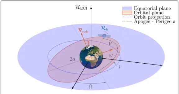
6.1.2 Orbital mechanics . . . 124
6.1.3 External disturbances . . . 128
6.2 Space Robot Modeling . . . 131
6.2.1 Dynamic coupling . . . 131
6.2.2 Dynamics Algorithms . . . 141
6.2.3 Simplifying hypothesis about orbital dynamics . . . 149
CHAPTER 7 PATH PLANNING FOR DEBRIS CAPTURE . . . 152
7.1 Target Motion . . . 152
7.1.1 Debris dynamics and target point kinematics . . . 152
7.2 Optimal Robot Guidance . . . 155
7.2.1 Optimal problem statement . . . 155
7.2.2 Optimal trajectories . . . 158
CHAPTER 8 SPACE ROBOT CONTROL . . . 170
8.1 Control Architecture . . . 170 8.1.1 Inner Loop . . . 171 8.1.2 Outer Loop . . . 173 8.2 Controller Synthesis . . . 176 8.2.1 List of requirements . . . 176 8.2.2 Linearized model . . . 177 8.2.3 Synthesis scheme . . . 179 8.2.4 Results of synthesis . . . 181 8.3 Robust Analysis . . . 187
8.3.1 Robotic arm parameterization . . . 188
8.3.2 LFT parameterization of a rotation matrix . . . 190
xiv
8.3.4 Robust performance analysis . . . 202
CHAPTER 9 VALIDATION OF CONTROL LAWS . . . 206
9.1 Numerical Validation . . . 207
9.1.1 High-fidelity simulator . . . 207
9.1.2 Simulation results . . . 209
9.2 Experimental Validation . . . 215
9.2.1 Pros/Cons of an Earth-based Simulator . . . 215
9.2.2 Test bench layout . . . 217
9.2.3 Experimental results . . . 224
CHAPTER 10 CONCLUSION AND RECOMMENDATIONS . . . 230
10.1 Summary of contributions . . . 230
10.2 Recommendations for future works . . . 232
BIBLIOGRAPHY . . . 235
LIST OF TABLES
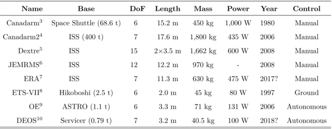
Table 1.1 Characteristics of the main space robotic arms . . . 15
Table 5.1 RMS energy drift and computation time ratios for both examples . . 120
Table 8.1 List of constraints and requirements . . . 177
Table 8.2 Gains setting of the decentralized arm controller . . . 183
Table 8.3 Natural flexible frequencies of the robotic arm and of the solar arrays (in rad/s) . . . 185
Table 8.4 Gains setting of the decentralized arm controller for the mono-model approach . . . 186
Table 8.5 Subsets of the joint angles guaranteeing stability by µ-analysis . . . 202
Table 8.6 Subsets of the joint angles guaranteeing performance by µ-analysis . 204 Table 9.1 Proportional gains setting of the decentralized and centralized arm controllers . . . 213
Table 9.2 Mean error and variance of the relative distance during the capture . 228 Table A.1 Denavit-Hartenberg parameters for the Canadarm in Figure A.4 . . . 264
Table B.1 Boundary conditions for a clamped-loaded beam . . . 291
Table D.1 Data of 2 DoFs planar robot (SI units) . . . 333
Table D.2 Data of the 6 DoFs Canadarm manipulator (SI units) . . . 335
xvi
LIST OF FIGURES
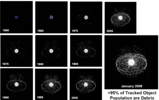
Figure 1.1 Evolution of the debris population over the space exploration . . . 2
Figure 1.2 Monthly number of cataloged objects in Earth orbit . . . 4
Figure 1.3 Laser Orbital Debris Removal (LODR) concept by C. Phipps . . . 5
Figure 1.4 Examples of on-orbit deorbitation methods with and without contact 6 Figure 1.5 Most promising methods to capture a debris . . . 7
Figure 1.6 Most advanced projects of humanoid robotics in space . . . 8
Figure 1.7 Typical servicing/debris removal mission profile . . . 10
Figure 1.8 Human-like structure of the Canadarm . . . 11
Figure 1.9 Most significant space robotics missions for servicing/debris removal . 14 Figure 1.10 Balance between fulfilled and remaining challenges for on-orbit servicing 17 Figure 2.1 Jacobian-based control for fixed-base robots . . . 24
Figure 2.2 Elastic joints of a robotic arm . . . 25
Figure 2.3 Flexible links of a robotic arm . . . 26
Figure 2.4 Keplerian elements of an orbit . . . 32
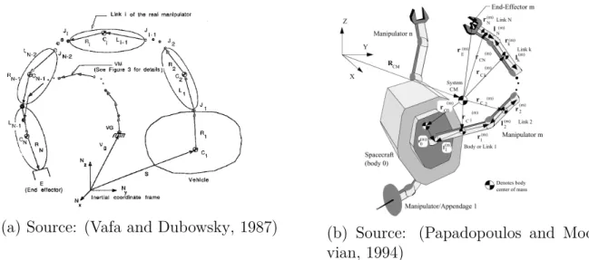
Figure 2.5 Kinematics of space robots . . . 34
Figure 2.6 Workspace analysis for space robots . . . 36
Figure 2.7 Manipulability comparison between fixed-base and space robots . . . 37
Figure 2.8 Two trajectories of the target for different initial tumbling rate of the debris . . . 43
Figure 2.9 Limit curve concept and switching point choices . . . 45
Figure 2.10 Singularity avoidance by modifying the initial configuration of the space robot . . . 47
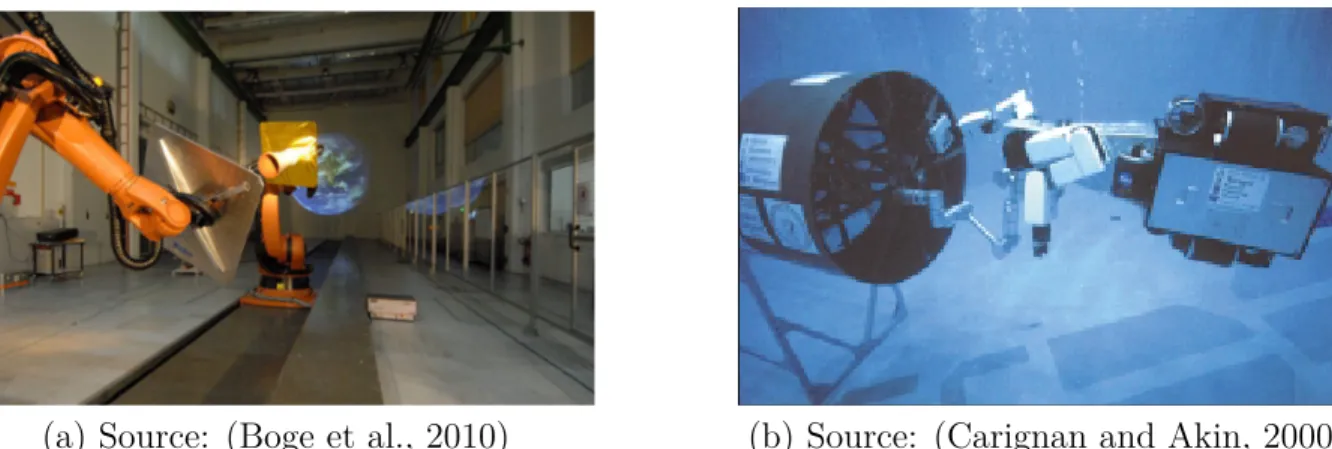
Figure 2.11 Test benches to validate space robotics on Earth . . . 52
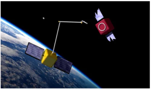
Figure 3.1 Illustration of the on-orbit capture of a debris by a space robot . . . . 55
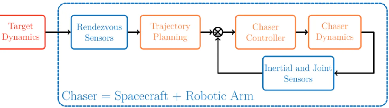
Figure 3.2 Global control architecture of the system and topics of the thesis in the orange blocks . . . 58
Figure 4.1 Kinematics of a rigid segment . . . 61
Figure 4.2 Adapted Denavit-Hartenberg frames for the Canadarm example . . . 69
Figure 4.3 Forward dynamics scheme for numerical simulation of rigid multi-body systems . . . 86
Figure 5.1 Kinematics of a flexible segment . . . 88
Figure 5.2 Flexible behavior of a beam in each direction . . . 89
Figure 5.4 Forward dynamics scheme for numerical simulation of flexible
multi-body systems . . . 111
Figure 5.5 Simulation results for the planar example. . . 115
Figure 5.6 Classic Denavit-Hartenberg frames for the Canadarm manipulator . . 116
Figure 5.7 Joint torques for the Canadarm example . . . 116
Figure 5.8 Simulation results for the Canadarm example. . . 118
Figure 5.9 Approximation errors for the Canadarm example. . . 119
Figure 5.10 Computation time according to simulation time step for the Canadarm example. . . 121
Figure 6.1 Usual components of a spacecraft . . . 124
Figure 6.2 Keplerian elements of the elliptical orbit . . . 125
Figure 6.3 Frames assignment on a spacecraft with various appendages . . . 132
Figure 7.1 Debris kinematics and target point location . . . 153
Figure 7.2 Example of an optimal capture trajectory by matching the position . 161 Figure 7.3 Example of an optimal capture trajectory by matching position and speed . . . 165
Figure 7.4 Example of an optimal capture trajectory by matching position, speed and acceleration . . . 168
Figure 8.1 Decentralized control architecture between the AOCS and the arm’s controller . . . 171
Figure 8.2 Outer control loop of the space robot based on the Jacobian matrix . 174 Figure 8.3 Manipulability index of the manipulator of the space robot . . . 175
Figure 8.4 H∞ synthesis scheme . . . 180
Figure 8.5 Frequency responses on the acceleration sensitivity function for the rigid decentralized arm controller . . . 182
Figure 8.6 Analysis of the rigid decentralized arm controller used on a different arm configuration . . . 183
Figure 8.7 Frequency responses on the acceleration sensitivity function for the rigid centralized arm controller . . . 184
Figure 8.8 Pole-zero map of the rigid decentralized arm controller on the flexible model . . . 184
Figure 8.9 Frequency responses on the acceleration sensitivity function for the flexible controller . . . 186
Figure 8.10 LFT model of an uncertain system . . . 187 Figure 8.11 LFT model of a rotation w.r.t. a varying angle θi parameterized by σi 190 Figure 8.12 LFT scheme to parameterize the rotation θ along Z with σ2 = tan(θ/2) 192
xviii
Figure 8.13 LFT scheme to parameterize the rotation θ along Z with σ4 = tan(θ/4) 194
Figure 8.14 Computation of the µ-bounds for stability with σ2-parameterization . 200
Figure 8.15 Reduction of the joint upper limit by a µ-bound of 1.3 . . . . 201 Figure 8.16 Reduced computation of the µ-bounds for stability with σ2-parameterization
of θ5 . . . 203
Figure 8.17 LFT form of the linearized model of the robotic system including the performance transfer. . . 203 Figure 8.18 Computation of the µ-bounds for performance with σ2-parameterization204
Figure 8.19 Singular values of the weighted performance transfer for the uncertain flexible model . . . 205 Figure 9.1 Schematic view of the bodies and frames involved in the simulation . 207 Figure 9.2 Simulation scheme based on the inner/outer loops . . . 208 Figure 9.3 Results of simulation for the decentralized controller on the rigid space
robot model . . . 211 Figure 9.4 Results of simulation for the centralized controller on the rigid space
robot model . . . 212 Figure 9.5 Mass of fuel consumed during the maneuver of capture . . . 213 Figure 9.6 Results of open-loop simulation for the decentralized controller on the
flexible space robot model . . . 214 Figure 9.7 Robotic test bench used to simulate the on-orbit kinematics of a capture215 Figure 9.8 Robotic test bench setup to simulate the on-orbit kinematics of a capture218 Figure 9.9 Frames introduced to describe the on-orbit capture on the robotic test
bench . . . 219 Figure 9.10 Rail motion according to the relative position of the arm base from the
target in simulation . . . 220 Figure 9.11 Global HIL structure of the Simulink scheme emulating the the
on-orbit dynamics . . . 221 Figure 9.12 Image processing to identify the target position and attitude from the
embedded camera . . . 223 Figure 9.13 Visual interface of the simulator to check the on-orbit capture . . . . 225 Figure 9.14 Delay in the IRC5 control loop of the industrial manipulator . . . 226 Figure 9.15 Vector components from the chaser’s end-effector to the target point . 227 Figure A.1 Classic Denavit-Hartenberg parameters . . . 260 Figure A.2 Modified Denavit-Hartenberg parameters . . . 261 Figure A.3 Adapted Denavit-Hartenberg parameters . . . 262 Figure A.4 Different Denavit-Hartenberg frames depending on the convention . . 263
Figure B.1 Flexible behavior of the beam in each direction . . . 289
Figure B.2 Undeformed kinematics along the segment slender part . . . 295
Figure C.1 Frames assignment on a spacecraft with various appendages . . . 313
Figure D.1 Planar robot with 2 DoFs . . . 332
Figure D.2 Canadarm manipulator with 6 DoFs . . . 334
Figure D.3 Robotic manipulator with 6 DoFs designed by MDA . . . 336
xx
LIST OF SYMBOLS AND ABBREVIATIONS
ABA Articulated-Body Algorithm.
ACS Attitude Control System.
ADR Active Debris Removal.
AMM Assumed Mode Method.
AOCS Attitude and Orbital Control System.
ASAT Anti-SATellite weapon.
ASTRO Autonomous Space Transport Robotic Orbiter.
ATV Automated Transfer Vehicle.
CMG Control Moment Gyroscope.
CNES Centre National d’Études Spatiales.
CoM Center of Mass.
COPUOS Committee On the Peaceful Uses of Outer Space.
CRBA Composite Rigid Body Algorithm.
CSA Canadian Space Agency.
DARPA Defense Advanced Research Projects Agency.
DeNOC Decoupled Natural Orthogonal Complement.
DEOS DEutsche Orbitale Servicing mission.
DH Denavit Hartenberg.
DLR Deutsches zentrum für Luft- und Raumfahrt.
ECI Earth-Centered Inertial.
EKF Extended Kalman Filter.
EPOS European Proximity Operations Simulator.
ERA European Robotic Arm.
ESA European Space Agency.
ETS Engineering Test Satellite.
EVA Extra-Vehicular Activity.
FEM Finite Element Method.
FREND Front-end Robotics Enabling Near-term Demonstration.
GJM Generalized Jacobian Matrix.
GPS Global Positioning System.
HIL Hardware-In-the-Loop.
HTV H-II Transfer Vehicle.
IADC Inter-Agency space Debris Coordination Committee.
IMU Inertial Measurement Unit.
ISS International Space Station.
JAXA Japan Aerospace eXploration Agency.
JEMRMS Japanese Experiment Module Remote Manipulator System.
KF Kalman Filter.
LEO Low Earth Orbit.
LFT Linear Fractional Transformation.
xxii
LPV Linear Parameter Varying.
LQR Linear Quadratic Regulator.
MDA MacDonald, Dettwiler and Associates.
MIT Massachusetts Institute of Technology.
NASA National Aeronautics and Space Administration.
NASDA NAtional Space Development Agency.
NBV Neutral Buoyancy Vehicle.
NextSat Next generation Satellite.
NOC Natural Orthogonal Complement.
NORAD North American Aerospace Defense Command.
ODE Ordinary Differential Equation.
OE Orbital Express.
OLEV Orbital Life Extension Vehicle.
ORU Orbital Replacement Unit.
OST Outer Space Treaty.
PD Proportional-Derivative.
PDE Partial Differential Equation.
PID Proportional-Integral-Derivative.
RGE Recursive Gaussian Elimination.
RHS Right Hand Side.
RMS Root Mean Square.
RNEA Recursive Newton-Euler Algorithm.
ROKVISS RObot Komponent Verification on ISS.
RSSS Russian Space Surveillance System.
RW Reaction Wheel.
SDT Satellite Dynamics Toolbox.
SRMS Shuttle Remote Manipulator System.
SSN Space Surveillance Network.
SSTS Space Surveillance and Tracking Segment.
SUMO Spacecraft for the Unmanned Modification of Orbits.
TAS Thales Alenia Space.
TCS Thermal Control System.
TECSAS TEChnology SAtellites for demonstration and verification of Space systems.
TLE Two-Line Elements.
TRL Technology Readiness Level.
UN United Nations.
xxiv
LIST OF APPENDICES
Appendix A RIGID MODELING DETAILS . . . 259 A.1 Denavit-Hartenberg Parameters . . . 259 A.2 Euler Angles and Quaternions . . . 264 A.3 Rigid Dynamics Algorithms . . . 268 Appendix B FLEXIBLE MODELING DETAILS . . . 288 B.1 Assumed Mode Method . . . 288 B.2 Computation of the Flexible Mass Matrix . . . 294 B.3 Quasi-Lagrangian Equations . . . 304 Appendix C SPACE ROBOT MODELING DETAILS . . . 313 C.1 Space Robot Dynamics Algorithms . . . 313 Appendix D MANIPULATOR AND SPACECRAFT DATA . . . 332 D.1 Robotic Arms Data . . . 332 D.2 Spacecraft Data . . . 339
LIST OF PUBLICATIONS
The main contributions of the thesis have led to various publications in conferences and journals. The most recent ones are still being finalized, and will soon be submitted to the corresponding journal.
(Dubanchet et al., 2014) V. Dubanchet, D. Saussié, D. Alazard, C. Bérard, and C. Le Peuvédic, “Modeling and control of a space robot for active debris removal”, in Proceedings of the 9th International ESA Conference on Guidance, Navigation and Control, 2014, vol-ume 1, pages 1–19.
(Dubanchet et al., 2015a) V. Dubanchet, D. Saussié, D. Alazard, C. Bérard, and C. Le Peuvédic, “Modeling and control of a space robot for active debris removal”, in CEAS Space Journal, volume 7, issue 2, pages 203–218, 2015.
(Dubanchet et al., 2015b) V. Dubanchet, D. Saussié, D. Alazard, C. Bérard, and C. Le Peuvédic, “Motion Planning and Control of a Space Robot to Capture a Tumbling Debris”, in Advances in Aerospace Guid-ance, Navigation and Control: Selected Papers of the Third CEAS Specialist Conference, Springer Publishing, volume 1, pages 699–717, 2015.
(Dubanchet et al., 2016a) V. Dubanchet, D. Saussié, D. Alazard, C. Bérard, and C. Le
Peuvédic, “Influence of corrective terms in flexible manipu-lators dynamics using the DeNOC approach”, in (to be sub-mitted to) Journal of Dynamic Systems, Meas., and Control
(ASME), 2016.
(Dubanchet et al., 2016b) V. Dubanchet, D. Saussié, D. Alazard, C. Bérard, and C. Le
Peuvédic, “LFT Modeling and Robust Performances Analysis of a Rigid Multi-Body System”,in (to be submitted to) IEEE
1
CHAPTER 1 INTRODUCTION
Space science and technology have known a tremendous leap forward in the last century, bringing into orbit all kinds of satellites and rocket stages. Nowadays, most of these objects are no longer functional and are classified as space debris. They have multiplied at an increasing pace over the last years, reaching a tipping point where their natural decay with the atmospheric drag is no longer sufficient to counter this rise. In 1978, the scientists D. J. Kessler and B. G. Cour-Palais pointed out for the first time that such a density of orbiting bodies would lead to an increasing probability of collision, that could create a debris belt around the Earth (Kessler and Cour-Palais, 1978) (see Figure 1.1). Exploring these probabilistic scenarios through extensive simulations, J.-C. Liou eventually demonstrated that the “Kessler syndrome” is already engaged, meaning that, the debris would multiply in an unstoppable chain reaction without human intervention (Liou and Johnson, 2009). The only remaining uncertainty in these studies is whether the loss of space access will happen in a near or far future, depending on the growth rate of the debris population.
These objects are giving rise to two main issues: they threaten the functional satellites and endanger the astronauts aboard the International Space Station (ISS) or during Extra-Vehicular Activity (EVA) (Selding, 2014; Woods, 2015). Due to their very high speed, around 10 km/s, they can cause serious damages depending on their size. In addition, they will stay in orbit for years or centuries depending on their trajectory. According to the French space agency Centre National d’Études Spatiales (CNES), the actual debris population is divided into three main categories:
• 350,000,000 debris smaller than 1 cm, of low risk ; • 300,000 debris between 1 cm and 10 cm, of high risk ; • 16,000 debris bigger than 10 cm, of moderate risk.
Among these, the medium size debris are the most hazardous because they are too small to be tracked by ground systems, but big enough to cause disastrous damages on a functional satellite (Johnson, 2009). Actual materials for shielding allow the satellite to endure impacts with the smallest ones, and the biggest ones are tracked from ground to prevent any impact by performing avoidance maneuvers.
Figure 1.1: Evolution of the debris population over the space exploration.
Source: NASA - http://orbitaldebris.jsc.nasa.gov/photogallery/beehives.html#geo
1.1 Space Debris Mitigation
Following the recommendations of J.-C. Liou in (Liou et al., 2010), at least 5 massive debris must be deorbited per year to stabilize the actual population and avoid the Kessler syndrome. Indeed, these objects are more likely to create new debris by colliding with one another and hence represent the main objective of mitigation missions. In the next section, a general and technical overview is given over the main issues involved in a debris removal mission, from the legal framework to technical considerations.
1.1.1 Today’s issues
The space debris issue is mainly tackled by a working group of the United Nations (UN) called the Committee On the Peaceful Uses of Outer Space (COPUOS). It provides many data about the actual space pollution, and draws some recommendations and guidelines to reduce as much as possible the current human footprint (COPUOS, 1999). Among its members, the most influent space agencies around the world also created the Inter-Agency space Debris Coordination Committee (IADC) in 1993, which aims at cooperating more closely to perform the necessary technical studies.
Recommendations For example in 2007, the IADC wrote the Space Debris Mitigation Guidelines, and this document served as a reference for the COPUOS report (COPUOS, 2010). These recommendations encourage end-of-life procedures to deorbit satellites and
3
rockets, and aim at preventing catastrophic collisions or breakups. Indeed, two main events worsened the situation in the 2000s. In 2007, the Chinese decided to test an Anti-Satellite missile in Low Earth Orbit (LEO) on their Fengyun-1C satellite, and in 2009, a collision occurred between an American satellite, Iridium 33, and a Russian one, Cosmos 2251. These events increased the number of debris of 4,000 and 2,500 pieces, respectively.
Surveillance Most of the actual debris greater than 10 cm can be tracked from the ground thanks to surveillance networks like the United States (US) facility called Space Surveillance Network (SSN), capable of detecting objects greater than 10 cm (Wright, 2010) in LEO. The measurements are turned into the famous Two-Line Elements (TLE) dataset by the North American Aerospace Defense Command (NORAD), in order to describe the orbital parameters of these objects. These data are available for example https://celestrak.com. Thanks to such a system, the evolution of space debris population has been observed since the launch of the first satellite, Sputnik, by the Russians on October 4th, 1957. The result is
illustrated in Figure 1.2.
For autonomy purposes, the Russians also own a similar space surveillance system, the Rus-sian Space Surveillance System (RSSS) also known as SKKP. Even though currently less efficient, the European Space Agency (ESA) is developing a third major facility called Space Surveillance and Tracking Segment (SSTS).
Selection Once the space debris are cataloged, one needs to choose the most relevant objects to deorbit. For example, in (Couzin et al., 2013), a mission-based approach is used, so space debris are sorted for a given range of orbital inclination and altitude. It highlights which groups are reachable with a minimum of maneuvers in a multi-target removal scenario. On the other hand, from a risk-based approach, C. Bonnal focuses on the criticality of each object in orbit. Its size and mass strongly influence its probability of collision with others, as well as the overcrowding of its orbit. In the same way, the top 500 objects with the highest collision probability are drawn up in (Liou, 2011), and provide a solid starting point.
Legal Framework Prior to the treatment of any debris, one major issue remains about the definition of its nationality. This is supposed to determine the liability of a given country to clean it up. As emphasized by (Weeden, 2011; Ansdell, 2010), many definitions can be adopted to choose this country: is it the one that built the object? that launched it? that operated it? All these questions are still open, but steps forward have been made with the United Nations (UN), through the Outer Space Treaty (OST) defined in 1967, and the Liability Convention adopted in 1972. This legal framework is also supposed to dictate how the price of an active debris removal mission must be shared between the liable countries.
Fengyun-1C Iridium 33 / Cosmos 2251
Figure 1.2: Monthly number of cataloged objects in Earth orbit, tracked by the Space Sur-veillance Network (SSN). The last two peaks are due to the breakup of the Chinese satellite Fenguyun-1C in 2007, and to the collision of Iridium/Cosmos in 2009.
Source: National Aeronautics and Space Administration (NASA) - Orbital Debris Quarterly News - April 2016 - vol. 20 (1-2), annotated.
Disintegration Eventually, the debris disintegration is the last source of concern. The consumed portion of a body during the atmospheric re-entry is hardly known due to its un-predictable nature, which fostered active researches on the matter. For example, a complete simulation software called SCARAB is proposed in (Fritsche et al., 2000). All the components of a satellite can be specified in terms of material and shapes, and simulations are performed at structural and thermal levels to predict the level of disintegration on a given re-entry orbit. This issue drives C. Bonnal to recommend, in (Bonnal et al., 2013), an Active Debris Removal (ADR) scenario with a controlled target trajectory, instead of a simple uncontrolled re-entry.
1.1.2 Potential technical solutions
The emphasis is now put on the technical solutions that allows to safely deorbit a space debris. Some of them provide remote effects or direct efforts in the common goal to lower the debris altitude and drive it to a re-entry trajectory that will consume it entirely. A major difference must also be made between the deorbitation concepts and the capture devices requiring a
5
physical contact. In the sequel, the term “non-cooperative” means that the capture must be performed for tumbling objects without any visual marker nor grappling fixtures (Bonnal et al., 2013).
Deorbitation devices Among the many solutions proposed in the literature, they first differ by the way they act on the debris. The choice is made here to present the ground-based concepts and the on-orbit ones as two different families.
Figure 1.3: Laser Orbital Debris Removal (LODR) concept by C. Phipps.
Source: (Phipps, 2014) • From ground: As mentioned earlier
with the Chinese satellite breakup, an Anti-SATellite weapon (ASAT) missile could be launched directly from the ground to inter-cept and destroy a space debris. This idea is obviously left aside for ADR missions since it only dismantle a big debris into smaller pieces and does not solve their threat. Another remote action is possible through the laser ablation technology presented by (Phipps et al., 1996). It consists in hitting the debris with a high-energy pulsed laser in order to locally ablate material, as shown in
Figure 1.3. The resulting jet of plasma creates an impulse force on the debris by the reaction principle. This approach remains only effective in a short amount of time for the smallest debris (<10 cm), but can also be considered to slightly lower the altitude of massive debris in order to reduce the threat they represent on crowded orbits.
• On-orbit: Due to the hazardous re-entry of a debris treated from the ground, most of actual concepts turn to on-orbit scenarios. Again, both kind of devices are encountered to exert a force on the debris, with or without contact.
– Contactless: As a variant of the previous idea, space-based lasers are proposed in (Schall, 1998) and (Phipps, 2014). The main advantages are to avoid the crossing of the atmosphere and to allow for the use of lasers of lower energy. Instead of creating the plasma by ablating matter, M. Merino et al. (Merino et al., 2011) proposed to generate it on board, and then to throw it toward the debris to drive it, as shown in Figure 1.4a. In the same way, an ESA study proposes to form a foam ball around the debris by throwing it from the chaser (Andrenucci et al., 2011). It would increase the
(a) Source: (Wormnes et al., 2013) (b) Source: JAXA Figure 1.4: Examples of on-orbit deorbitation methods with and without contact. (a) Ion beam thrown toward a debris; (b) Concept of an electrodynamic tether.
surface to mass ratio of the debris, and consequently improve the drag effect to lower its altitude.
Other contactless concepts focus on magnet-based actuators embedded on a chaser to move the debris with the induced Eddy currents (Ortiz Gómez et al., 2016). In addition to the small forces applied, this approach requires a very accurate formation flight between the chaser and the target (Fabacher et al., 2015).
– Contact: Concerning the devices which need a physical contact with the debris, one can find electrodynamic tethers, solar sails or even deorbiting kits with a small engine (Bonnal et al., 2013). The first ones are long wires suspended to the object, and undergo a drag force due to the Earth magnetic field, which is transmitted to the debris, as illustrated in Figure 1.4b. A thorough overview to assess the pros and cons is given in (Pardini et al., 2009), where the probability of impact with small orbiting debris is evaluated for these appendages spreading over many kilometers. To give an idea, in 1996, the French satellite Cerise lost its mast of only 3 m by a collision with an orbiting debris (Alby et al., 2007). Eventually, the last option with a deorbiting kit would be the best solution for a controlled re-entry (Couzin et al., 2013). Nevertheless, the kit itself is much heavier than the tether solution, since it contains a rocket with its propulsion and can reach hundreds of kilograms.
7
(a) Source: (Wormnes et al., 2013) (b) Source: ESA - eDeorbit Figure 1.5: Most promising methods to capture a debris.
(a) Pulling technology with a net grasping; (b) Pushing technology with a clamping mecha-nism.
As a conclusion about the deorbitation technologies, some of them appear more suited for small debris, like the laser ablation or the foam expansion, and others are more effective for big debris, like the electrodynamic tethers or the deorbiting kits. For the latter, a capture is necessary to append the kit on the debris.
Capture devices Again, many solutions are under development, like nets, harpoons or robotic arms. A survey is provided in (Wormnes et al., 2013) from the ESA point of view. Pulling technologies using nets and harpoons are emphasized for mono-target scenario. The chaser would capture only one debris and then pull it toward the Earth to burn with it (see Figure 1.5a). In a multi-target scenario, solid propulsion deorbiting kits offer a better compromise since a chaser could embed many of them in a single mission (Castronuovo, 2011). Focusing on this concept, C. Bonnal comes to the conclusion that a robotic arm is the best compromise to perform both capture and kit fastening (Bonnal et al., 2013). In addition, this technology is the main option for on-orbit servicing and its Technology Readiness Level (TRL) is already higher than most of its competitors (NASA, 2010) (see Figure 1.5b).
According to the previous analyses, space robotics emerges as one of the key technology for active debris removal, as well as the nets and harpoons concepts. The present thesis naturally builds upon the strengths of the robotic arm solution. In the sequel, a typical mission is described for such a capture mechanism. Within this description, the parts addressed by this thesis are highlighted. A review of the past and current robotic missions for both on-orbit servicing and debris capture is also provided to enhance the remaining fields of improvement for these technologies.
(a) Source: (Diftler et al., 2011)
(b) Source: (Fuchs et al., 2009) Figure 1.6: Most advanced project of humanoid robotics in space.
(a) Robonaut2 project from NASA and General Electric ; (b) Rollin’Justin from the DLR.
1.2 On-Orbit Space Robotics
The latest developments about all the fields of space robotics can be found in the surveys of K. Yoshida in (Yoshida, 2009), of L. Pedersen et al. in (Pedersen et al., 2003), or in the more technical paper of A. Flores-Abad et al. in (Flores-Abad et al., 2014). Apart from the in-space technologies, they also go deeply into mobile robotics, covering the vast fields of robotic motion on-ground, perception, image analysis, path planning in an a priori unknown environment, etc. Impressive humanoid robots are also being developed to help and replace astronauts in hazardous operating conditions. The more advanced ones are the American Robonaut2, which was already sent on the ISS (Diftler et al., 2011), and the German Rollin’Justin (Fuchs et al., 2009). They are respectively illustrated in Figure 1.6a and Figure 1.6b.
In the present work, the stress is put on the projects including robotic arms embedded on a spacecraft to capture cooperative or non-cooperative objects. This last point split the fields of application into two main branches: the on-orbit servicing and the active removal of massive debris. They both ask for similar technologies, but the main difference lies in the nature of the object to catch: for the debris removal issue, no handle or visual marker are present during capture, and the object can be rotating at high rates. The capabilities of the involved technologies have already been demonstrated on servicing scenarios, but remains an open question in the case of the on-orbit capture of a tumbling debris.
Sys-9
tem (SRMS), the Canadian robotic arm embedded on the Space Shuttle in the 80’s and nicknamed Canadarm. To name but a few, the Canadarm allowed to capture the famous Hubble telescope for repairs in the early 90’s, the Japanese space agency Japan Aerospace eXploration Agency (JAXA) demonstrated a collaborative capture with the Engineering Test Satellite (ETS)-VII project in 1997, and the Americans performed autonomous rendezvous and semi-autonomous capture and berthing with the Orbital Express (OE) mission in 2006. They are presented into more details through the next sections to draw a brief overview of the maturity of actual technologies.
1.2.1 Typical mission scenario
The sequence of events usually performed for an autonomous rendezvous and capture is well described in (NASA, 2010) for servicing, and in (Rekleitis et al., 2007; Bonnal et al., 2013) for debris removal. To summarize, the mission has the following steps:
1. Long-Range Rendezvous: from 25 km to 300 m from the target (see Figure 1.7a); 2. Short-Range Rendezvous: from 300 m to 50 m (see Figure 1.7b);
3. Fly Around & Data acquisition: estimation and propagation of the target dynamics1,
path planning for the capture (see Figure 1.7c);
4. Capture: deployment of the capture mechanism, interception trajectory, and mechani-cal interfacing with the target; (see Figure 1.7d);
5. Post-Capture: de-tumbling and securing of the composite system (chaser+target), berthing to release the load on the capture mechanism (see Figure 1.7e);
6. Service Operations: refueling or unit change for servicing, or fixation of a deorbitation kit for ADR (depending on the strategy) (see Figure 1.7f);
7. Final Step: release for servicing, or deorbitation for ADR.
More details about the mission profile are available through (Castronuovo, 2011; Guariniello et al., 2011) from the debris removal point of view. One key point, which is still undergoing intensive tests, is the choice of the point of capture on the debris. Since the target does not possess any handle, the focus is set on common features, like the launcher ring or on the nozzle of the apogee kick motor. The first one is common to any satellite and its counterpart is also present on the orbiting rocket upper stages, making it more attractive to capture these
Long Range (25km - 300m)
(a) Long-Range Rendezvous
Short Range (>300m)
(b) Short-Range Rendezvous
Observation & Planning (~50m)
(c) Fly Around
Mechanical Interfacing
(d) Capture
De-tumbling & Berthing
(e) Post-Capture
Servicing or Removal Operation
(f) Service Operations Figure 1.7: Typical servicing/debris removal mission profile
two types of debris with the same system (Castronuovo, 2011; Obermark et al., 2007). The second one is most common for geostationary satellites, since they need an extra impulse to reach their final orbit. The nozzle provides a feature strongly enough to dock on it and then manipulate the whole spacecraft through it (Yoshida and Nakanishi, 2003; Boge et al., 2010).
1.2.2 Past missions overview
Among the few missions mentioned above, the three main ones involved a robotic capture with different levels of autonomy. A full description of each mission achievements regarding this autonomy and the task performed by the robotic arms is done in (Rekleitis et al., 2007).
11
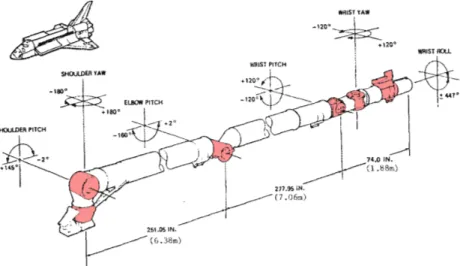
Figure 1.8: Human-like structure of the Canadarm (6 joints). Source: (Aikenhead et al., 1983)
The next paragraphs illustrate especially the robotic tasks performed during these missions, and do not extend to other interesting aspects, like the autonomous rendezvous. Indeed, this issue has already been demonstrated and is common for projects like the Automated Transfer Vehicle (ATV) by ESA (Wikipedia, 2013a), or the H-II Transfer Vehicle (HTV) by JAXA (Wikipedia, 2013b). Conversely, space robotics are still under advanced developments to increase their autonomy level. The Canadian robotic arm embedded on the Space Shuttle is presented first, then the contributions of the Japanese mission ETS-VII and of the American one Orbital Express are emphasized. For each of them, illustration are provided in Figure 1.9.
1.2.2.1 Canadian SRMS
Manually controlled robotic arm.
This arm was designed by a Canadian company called SPAR Aerospace at that time, and whose robotic division is now part of the MacDonald, Dettwiler and Associates (MDA) group. The arm was 15 meters long and had a structure similar to a human arm with a shoulder, a forearm, an elbow, an arm and a wrist, as illustrated in Figure 1.8. The two main beams were, respectively, around 6 and 7 meters long for a total mass of 450 kg (Aikenhead et al., 1983). Flexibility was a strong issue to control this arm because the first flexible mode fre-quencies were very low.
Reviews of its main missions are done in (Sachdev, 1986; Hiltz et al., 2001). Among the most important ones, the Canadarm used to inspect the thermal protection system of the Space
Shuttle before the atmospheric re-entry. In some cases, it reveals critical for the mission success and for the crew safety. For instance, it allowed to clean a venting port blocked with ice on the 41-D mission in 1984, and it regularly offered a safe base to maintain the astronaut during EVA.
In a nutshell, the Canadarm was the first space robotic arm and proved to be essential to carry out many tasks, from the repairing of malfunctioning satellites, to the inspection of the Space Shuttle itself, and even for the assembly of multi-pieces structures. But this arm was
controlled by the astronauts on-orbit, and did not offer any autonomy.
1.2.2.2 Japanese ETS-VII
Semi-autonomous robotic capture of a cooperative target.
In the late 90’s, the Japanese space agency, called at that time the NAtional Space Devel-opment Agency (NASDA), performed a visionary mission with the ETS-VII project. Based on two satellites, a chaser Hikoboshi of 2.5 tons and a target Orihime2 of 0.4 t, autonomous rendezvous and docking were carried out, including also robotic captures (Kasai et al., 1999). During the operations, the ground teleoperated the arm with a time delay of 6 to 7 seconds, thanks to relay satellites in geostationary orbit.
At the robotic level, the Toshiba Co. company designed its 6 Degree-of-Freedom (DoF) manipulator, with a mass of 45 kg, a span of 2 m and a power consumption of 80 W. It demonstrated a robotic release of the target with a relative motion of 1 mm/s in translation and 0.01◦/s in rotation (Inaba and Oda, 2000). Thanks to the onboard image processing and the handle marker on the target, the robotic arm was remotely controlled to re-capture it from the ground. A coordinated control was designed to perform the required robotic motion, while compensating for the large disturbances induced on the spacecraft (Oda, 1996, 1999). A simplified feedforward compensation was used by approximating the angular momentum transfer from the arm to the base (Oda, 1994).
It is worth reminding that this experiment was the first in history to perform an autonomous rendezvous in short-range, a refueling and an Orbital Replacement Unit (ORU) transfer in autonomous mode. The robotic arm was manipulated from the ground with semi-autonomous tasks, like “Move from point A to point B", or fully manually by driving its end-effector with joysticks (Kasai et al., 1999).
13
1.2.2.3 American Orbital Express
Autonomous capture of a cooperative target.
The last servicing demonstration took place with the Orbital Express (OE) mission sponsored by the American Defense Advanced Research Projects Agency (DARPA). It consisted of two satellites, the chaser of 1.1 t called Autonomous Space Transport Robotic Orbiter (ASTRO), and the target of 0.2 t named Next generation Satellite (NextSat). The first one was equipped with a 6 DoF robotic arm designed by MDA, with a mass of 71 kg, a span of 3.3 m and a power consumption of 131 W. It was able to capture and service the target, to perform a refueling and a battery and ORU replacements (Friend, 2008).
The mission demonstrated many autonomous rendezvous and docking, even for far-range scenarios (>5 km), and performed autonomous captures with the robotic arm. The docking mechanism was a brand new concept developed in (Timmons and Ringelberg, 2008; Stamm and Motaghedi, 2004).
The robotic arm was once again mainly designed to perform the servicing tasks, and in few scenarios to capture and lead the target for a safe berthing. This was the first time that a
fully autonomous capture by a robotic arm took place in space. But the object was a
cooperative spacecraft with visual markers and a fixed attitude.
The next section presents the robotic arms operating in space, and the missions under de-velopment which aim at demonstrating a non-cooperative capture.
1.2.3 Current and future missions
As mentioned above, the space robotics has one of the highest TRL among the servicing or debris removal technologies. The past missions described earlier demonstrated their benefits and many robotic arms are still in operation on the ISS. Moreover, some missions around the world are pushing further these fields of research to enforce for rendezvous and capture of non-cooperative objects in the coming years. A review of the actual robotic arms aboard the ISS is first made, and the main missions in preparation for debris removal or servicing are exposed. Again, some illustrations of the spacecraft concepts are given in Figure 1.9.
(a) Canadarm & Space Shuttle. Source: NASA
(b) ETS-VII mission. Source: JAXA
(c) Orbital Express mission. Source: DARPA (d) DEXTRE robotic arm. Source: NASA
(e) TECSAS/DEOS mission. Source: DLR (f) Phœnix mission. Source: DARPA Figure 1.9: Most significant space robotics missions for servicing/debris removal
15
Table 1.1: Characteristics of the main space robotic arms
Name Base DoF Length Mass Power Year Control
Canadarm3 Space Shuttle (68.6 t) 6 15.2 m 450 kg 1,000 W 1980 Manual Canadarm24 ISS (400 t) 7 17.6 m 1,800 kg 435 W 2006 Manual Dextre5 ISS 15 2×3.5 m 1,662 kg 600 W 2008 Manual JEMRMS6 ISS 12 12.2 m 970 kg - 2008 Manual ERA7 ISS 7 11.3 m 630 kg 475 W 2017? Manual ETS-VII8 Hikoboshi (2.5 t) 6 2.0 m 45 kg 80 W 1997 Ground
OE9 ASTRO (1.1 t) 6 3.3 m 71 kg 131 W 2006 Autonomous DEOS10 Servicer (0.79 t) 7 3.2 m 40.5 kg 100 W 2018? Autonomous
1.2.3.1 Robotic arms aboard the ISS
Among the most famous robotic arm brought up to the ISS, one can find the Canadarm2, its extension Dextre, the Japanese Experiment Module Remote Manipulator System (JEMRMS) as part of the Japanese module, the two Russian cranes Strela and the European Robotic Arm (ERA), about to be launched next year. Their main characteristics in terms of DoF or mass and span have been compiled in Table 1.1.
It is worth noticing the difference in dimension between these arms and the ones embedded in the previous missions. They are designed to carry huge loads on long distance when assembling modules, so they result in heavy structures and long span. Moreover, since the ISS is an extremely massive base compared to them, they do not impact much its attitude when moving and their inertia is not a concern.
On the contrary, when the mass ratio between the arm and the base is more critical, the attitude control of the spacecraft is much more challenging. This is why the robotic arms of ETS-VII or OE were much lighter.
3(Aikenhead et al., 1983) 4http://www.nasa.gov/mission_pages/station/structure/elements/mss.html 5 https://www.nasa.gov/mission_pages/station/structure/elements/dextre.html 6 http://iss.jaxa.jp/en/kibo/about/kibo/rms/ 7http://www.esa.int/Our_Activities/Human_Spaceflight/International_Space_Station/European_Robotic_Arm 8https://directory.eoportal.org/web/eoportal/satellite-missions/e/ets-vii 9http://www.slideserve.com/patsy/orbital-express-a-new-chapter-in-space 10(Rank et al., 2011)
1.2.3.2 Missions to come
Two main missions are supposed to be launched in the upcoming years: the German project for debris removal with DEutsche Orbitale Servicing mission (DEOS), and the American Phœnix.
The first one is illustrated in Figure 1.9e and is also built on the idea of a common launch with both the chaser and target. This project was originally called TEChnology SAtellites for demonstration and verification of Space systems (TECSAS) and was a cooperation between the German, Canadian and Russian space agencies (Martin et al., 2005; Flores-Abad et al., 2014). Unfortunately, it suffered reorientations from its involved members in 2006, such that Deutsches zentrum für Luft- und Raumfahrt (DLR) decided to take the lead alone and came up with the DEOS project since 200911. Its main goal is now to demonstrate an autonomous
rendezvous, fly-around, capture and stabilization of a non-cooperative debris (Reintsema et al., 2010). The DLR agency already demonstrated a great expertise in space robotics with the RObot Komponent Verification on ISS (ROKVISS) project embedded on the Russian module of the ISS (Hirzinger et al., 2004). Moreover, most of the developed technologies are also jointly used for the servicing project Orbital Life Extension Vehicle (OLEV), providing life extension for geostationary satellites. The DLR also validates intensively its technologies on the ground with the state-of-the-art robotic testbench European Proximity Operations Simulator (EPOS) wich allows for Hardware-In-the-Loop (HIL) experiments and rendezvous scenarios with satellite mockups (Boge et al., 2010; Boge and Ma, 2011).
The second mission of interest leans more toward on-orbit servicing, but it will push further many common technologies, like the robotic manipulation or the image processing. The Phœnix mission is built upon the legacy of two former missions. The original program was the Spacecraft for the Unmanned Modification of Orbits (SUMO), initiated in 2002 to capture and service malfunctioning satellites in geostationary orbits, and not initially designed for servicing purposes. Then followed the Front-end Robotics Enabling Near-term Demonstration (FREND) project as part of the SUMO program, one of whose main contributions was the design of a multi-purpose arm, used on the last Phœnix mission (Obermark et al., 2007). The advances of the image processing paved the way for an autonomous capture of non-cooperative objects at low tumbling rate (Flores-Abad et al., 2014). On the actual design of the Phœnix mission, three arms are embedded on the servicer: two of them service the target, and the third one is dedicated to image acquisition and processing allowing for much more
11
17
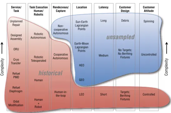
Chapter 4 | Satellite Servicing: The Implementation – The Map of Servicing Capabilities | 51 Figure 4.4 – Notional Mission Suite Coverage of the Servicing Study Trade Space – The notional missions were designed to
cover every area of the diagram so that we can sample a range of trade space possibilities.
Figure 4.3 – Servicing Study Trade Space Regions Covered by Historical Missions – This graphic summarizes the regions of the trade space diagram that have been sampled already (historical) or are yet to be sampled (unsampled).
Figure 1.10: Balance between fulfilled and remaining challenges for on-orbit servicing. Source: NASA (NASA, 2010)
flexibility during the operations. The arms are direct evolutions of the FREND program. One improvement is the design of new tools used at the end-effector and above all the capacity to change autonomously the tool to perform multiple tasks with the same arm (Sullivan et al., 2015). Even if this last project is conducted in the scope of on-orbit servicing, its demonstration will create strong assets for space robotics, especially useful in the future debris removal missions.
1.3 Remaining Challenges
As a conclusion, this introductory part has presented the most promising technologies for active debris removal and on-orbit servicing. First, the orbiting space debris have been clas-sified according to their size, their orbit, and their probability of collision. This ranking has allowed to exhibit a priority list for future removal missions, and to adapt the mission plan depending on the deorbitation method and the number of objects to treat.
Indeed, many concepts were presented to deorbit them, from the ground-based lasers to the capture devices. Nowadays, the two most promising technologies are the robotic arms and
the nets. Both emerge as the best compromises for the active debris removal, considering their maturity, their related risks, and the advantages they have. The focus has been mainly put on the space robotics, because of its versatility for servicing as well and its promising developments on the upcoming missions. A clear overview of the accomplished and remaining challenges is given in Figure 1.10 from the servicing standpoint.
The present introduction has also shown how autonomous rendezvous, fly-around and dock-ing have been performed in the past. In addition, the robotic captures were mainly achieved by astronauts or by tele-operation, and always with cooperative targets. Therefore, an au-tonomous capture with a non-cooperative object is still an open problem and fuel the current researches. Such debris must be captured with tumbling rates of a few degrees per second (Lampariello, 2013; Bonnal et al., 2013), and most often without any visual marker nor grap-pling fixtures (Inaba and Oda, 2000; Friend, 2008). These last points are intensive axes of research, along with the flexible behavior of such manipulators. Indeed, their structure is optimized to minimize as much as possible the global mass at launch. These lightweight arms exhibit very low frequency modes, that can severely degrade the controller performances.
Going further in the technical details, the next chapter brings an overview of the current research topics on the modeling and control of such systems. Based on this critical analysis of the literature, the research objectives and the expected contributions of the thesis are given.