RESPONSE OF COMPOSITE PANELS WITH CONDUCTIVE COATINGS SUBMITTED TO EMULATED LIGHTNING STRIKES
SRI MARKANDEYA RAJESH PONNADA DÉPARTEMENT DE GÉNIE MÉCANIQUE ÉCOLE POLYTECHNIQUE DE MONTRÉAL
THÈSE PRÉSENTÉE EN VUE DE L’OBTENTION DU DIPLÔME DE PHILOSOPHIAE DOCTOR
(GÉNIE MÉCANIQUE) AOÛT 2017
ÉCOLE POLYTECHNIQUE DE MONTRÉAL
Cette thèse intitulée :
RESPONSE OF COMPOSITE PANELS WITH CONDUCTIVE COATINGS SUBMITTED TO EMULATED LIGHTNING STRIKES
présentée par : PONNADA Sri Markandeya Rajesh en vue de l’obtention du diplôme de : Philosophiae Doctor a été dûment acceptée par le jury d’examen constitué de :
M. BOUKHILI Rachid, Ph. D., président
M. THERRIAULT Daniel, Ph. D., membre et directeur de recherche M. SIROIS Frédéric, Ph. D., membre et codirecteur de recherche M. SHESHYEKANI Keyhan, Ph. D., membre
DEDICATION
ACNKOWLEDGEMENT
This journey has only been possible because of the advice of experienced professors & industrial partners, the assistance of knowledgeable colleagues, the workmanship of many skilled personnel, the company of many good colleagues & friends and support of the funding agencies. A big “thank you” to each and everyone.
I thank the CRIAQ COMP-502 team for having initiated such an interesting project and my doctoral advisors Prof. Daniel Therriault and Prof. Frédéric Sirois for giving me the opportunity to be part of this learning experience. Thank you for your advice, encouragement and patience. This thesis would not have been complete without the selfless technical inputs and assistance of Lucile Moret and Sampada Bodkhe. I also wish to convey my sincere appreciation to David Fecteau, Isabelle Nowlan, Martin Gagne, Maxime Tousignant, Nicholas Veerabadren, Rouhollah Farahani, Samir Khalfaun, and Xavier Cauchy.
I would specially like to compliment the workmanship of the personnel from the building services: carpentry, electrical and plumbing, whose help was critical in building the lightning impulse emulator.
I will cherish the great time I had with friends from both the laboratory of multi-mechanics (LM2)
and laboratory of electrical energy and outside for a long time to come and wish them all the very best in their endeavors.
Sincerely,
RÉSUMÉ
De nouvelles méthodes de conception et de fabrication pour obtenir des matériaux conducteurs électriquement sont régulièrement développées. L’évaluation de la performance d'un matériau conducteur pour la protection contre la foudre (LCF) repose habituellement sur des essais et des analyses approfondis nécessitant l'accès à une infrastructure imposante. Cela peut entraîner des retards considérables dans le programme de recherche et / ou des dépenses déraisonnablement élevées. Cependant, lors de recherche exploratoire portant sur le développement de matériaux conducteurs pour LCF, il n'est financièrement pas viable ou techniquement productif de passer à travers la gamme complète de tests de foudre standardisés qui produisent des résultats binaires «go no-go». Le temps nécessaire pour de telles études approfondies est également difficile à justifier. Une étape de pré-qualification est donc souhaitable car elle peut servir de mécanisme de rétroaction pour améliorer la préparation/conception de matériaux avancés avant qu'ils ne soient soumis à des tests à grande échelle plus dispendieux et longs. Il est donc nécessaire de développer des équipements abordables et de nouveaux protocoles de test / analyse qui permettent une évaluation préliminaire mais holistique de nouveaux matériaux pour LCF. Cette nécessité est la principale motivation de cette thèse de doctorat.
Le premier objectif de cette thèse porte sur la conception de montages expérimentaux à faible coût en divisant le test de foudre standard en deux parties distinctes. Un nouveau circuit d'émulateur d'impulsions capable de produire une amplitude de crête de 40 kA a été conçu et fabriqué, tandis que des alimentations commerciales pouvant produire jusqu'à 500 A DC ont été utilisées pour tester les matériaux LSP contre des courants continus. Cet arrangement réduit la complexité et maximise la sécurité des circuits respectifs, menant à une meilleure rentabilité. Les émulateurs ont également été conçus avec une grande flexibilité afin d’accommoder des échantillons avec une large gamme de conductivités et pour reproduire diverses formes d'ondes. Les signaux d'onde émulés ici sont conformes aux normes SAE.
Le deuxième objectif porte sur la caractérisation et l'analyse des matériaux conducteurs. Différents matériaux conducteurs, chacun avec leurs propres méthodes de fabrication, ont été étudiés comme revêtements pour LCF de l'avion. Il s'agissait de différents métaux (argent, étain et un mélange cuivre-étain) et des matériaux hybrides (i.e., polymère carbone-argent et composite
à base d'argent). Une série d'essais a été effectuée en utilisant les émulateurs conçus lors du premier objectif. L'analyse des dommages reposait sur des techniques non destructives telles que les tests par ultrasons et la thermographie. La performance d’un panneau en composite non protégé renforcé par des fibres de carbone (substrat) et un autre substrat protégé à l’aide d’un grillage expansé en cuivre ont servi de référence à des fins de comparaison. On a observé que les matériaux composites avec des revêtements hybrides présentaient plus de dégâts que ceux avec revêtements métalliques. Il est intéressant de noter que le dommage dans la catégorie des revêtements hybrides était plus sévère que pour le cas de panneau composite non protégé. La méthodologie proposée dans cette thèse a permis une étude systématique des matériaux conducteurs pour LCF. Ces résultats aideront à améliorer la conception du matériau et finalement identifier les technologies les plus prometteuses pour les tests standards de protection contre la foudre.
Cette évaluation peut également servir d’inspiration comme tests et analyses pour d'autres applications. À titre d'exemple, les matériaux considérés pour la protection contre la foudre des appareils aériens pourraient aussi répondre aux exigences demandées par d’autres applications conductrices en aéronautiques comme les antennes, les capteurs de blindage électromagnétique, etc. La protection contre la foudre est reconnue comme l'un des paramètres les plus sévères pour la performance électrique. Aussi, il y a un grand intérêt par l’industrie aérospatiale pour des matériaux performants et légers. Afin de fabriquer quelques prototypes pour des applications telles que celles mentionnées ci-dessus, un procédé basé sur la combinaison des techniques de l'écriture directe, du masquage hydrophobe et du placage d'argent sans courant a été développé. Cette méthode consiste à limiter le placage d’argent à une zone préalablement délimitée avec l’impression d’un polymère sacrificiel et avec l’utilisation d’un revêtement hydrophobe. Des configurations conductrices avec une résolution de l'ordre de quelques centaines de microns ont être réalisées avec cette méthode. Les revêtements conducteurs ont été appliqués sur différentes surfaces selon les applications choisies.
En résumé, le montage expérimental et la méthodologie de recherche ont été développés pour mener des expériences contrôlées pour l'évaluation de la protection contre la foudre offerte par différents revêtements conducteurs appliqués sur des structures en composites. Ce travail contribue aux efforts de la communauté scientifique portant sur le développement de matériaux
avancés pour LCF. Ces découvertes mèneront à un transport aérien plus sécuritaire et plus écologique. La faisabilité d'étendre l'utilisation de revêtements conducteurs à d'autres applications aérospatiales au-delà de LCF a également été démontrée.
ABSTRACT
New design and manufacturing schemes to produce electrically conductive materials are regularly devised. The evolution of an electrically conductive material into a solution for lightning strike protection (LSP) relies on extensive testing and analysis requiring access to heavy infrastructure. This can lead to substantial delays in the research program and/or unreasonably high expenses. However, when exploring such conducting materials for LSP, neither is it financially viable nor technically productive to put them through the full battery of sophisticated lightning tests utilizing standard protocols that yield binary “go - no go” results. The time spent on such extensive studies is also difficult to justify. A pre-qualification program is thus desired. Such a program, if designed appropriately, can also serve as a feedback mechanism to improve on the materials’ technology readiness before they are subjected to full-scale tests. There is a need to develop low-cost equipment and associated test/analysis protocols that allow for a preliminary but holistic evaluation of new materials for LSP, which serves as the motivation for this PhD thesis.
The first objective of this thesis relating to the establishment of low-cost test equipment was achieved by dividing the standard lightning test into two separate parts of reduced severity. A new impulse emulator circuit capable of producing a 40 kA peak amplitude was designed and transformed into a physical structure, while commercial power supplies that could produce up to 500 A DC were used to test the LSP materials against continuous currents. This arrangement lowers complexity and safety demands on the respective circuits, hence leading to cost-effectiveness. The emulators were also designed with a flexibility to both accommodate samples with a wide range of conductivities, and reproduce current waveforms with chosen test parameters, leading to wider application. The emulated lightning waveforms were shown to conform to SAE standards.
The second objective concerns testing and analysis of conductive materials. Different conducting materials, each with their own manufacturing methods, were investigated as coatings for aircraft LSP. These included different metals (silver, tin and copper-tin) and hybrid materials (silver-carbon and silver-conducting polymer). A series of tests were conducted utilizing the designed emulators. Damage analysis relied on non-destructive techniques such as ultrasonic testing and
thermography. The performance of unprotected carbon fiber-reinforced polymer (substrate) and an expanded copper mesh-protected substrate formed the basis for comparison and evaluation. It was observed that the composites with hybrid coatings witnessed more damage compared to those with metallic coatings. Interestingly, the damage in the former category was even severe than that in unprotected CFRP. The proposed methodology allows for a systematic study of the conductive materials to aid in improving material design and ultimately identifying the most promising technologies for advanced lightning tests.
A “holistic” evaluation must also share a utilitarian view of research, i.e. the extension of the materials, tests, and analysis for other applications must also be inquired into. As an example, materials considered for aircraft lightning protection could meet the requirements of various other conducting aerospace applications like antennae, EMI shielding, sensors and so on. This is because lightning presents one of the harshest parameters for electrical duress while low density materials are a key demand of the aerospace industry. In order to realize designs of varied sizes and shapes with a useful degree of automation for applications such as those mentioned above, a method based on the fusion of direct-write techniques, hydrophobic masking and electroless plating of silver was developed. This method works by restricting the electroless wet chemistry (deposition) to an area that is previously printed with a sacrificial polymer and the surroundings masked with a hydrophobic coating. A resolution on the order of hundreds of microns can be realized with this method. Selective area coatings with different fabrication schemes and designs were demonstrated to illustrate the scope of application.
In summary, equipment and methodology was developed to conduct controlled experiments for the assessment of lightning strike protection offered by different conductive coatings to polymer composites. This work is believed to support the scientific community in its research on LSP materials for polymer aircraft, ultimately enabling greener and safer air travel. The feasibility to extend the utility of conductive coatings to other aerospace applications beyond LSP was also demonstrated, adding to the value of research .
TABLE OF CONTENTS
DEDICATION... iii ACNKOWLEDGEMENT...iv RÉSUMÉ...v ABSTRACT...viii TABLE OF CONTENTS... xLIST OF TABLES... xiii
LIST OF FIGURES...xiv
LIST OF SYMBOLS AND ABBREVIATIONS...xviii
CHAPTER 1 INTRODUCTION...1
CHAPTER 2 LITERATURE REVIEW...2
2.1 Lightning strikes to aircraft... 4
2.1.1 Aircraft in lightning environment...4
2.1.2 Lightning interaction with materials...5
2.1.3 Conductive materials for aircraft lightning protection... 8
2.2 Laboratory emulation of lightning...10
2.2.1 Test standards and procedures...10
2.2.2 Design of lightning current emulators...12
2.3 Characterization of lightning damage in the laboratory... 14
2.3.1 Lightning damage to composite materials...15
2.3.2 Visual, non-destructive, mechanical and spectroscopic analysis of damage...16
2.4 Summary of literature...21
CHAPTER 3 RESEARCH OBJECTIVES, METHODS AND RESULTS... 22
3.2 Thesis chapters, research articles and their coherence with the objectives... 24
CHAPTER 4 ARTICLE 1: DEVELOPMENT OF A 50 KA LIGHTNING CURRENT EMULATOR...26
4.1 Abstract...27
4.2 Introduction... 27
4.3 Conceptualization of the circuit...29
4.4 Mechanical and electrical design...34
4.4.1 Mechanical design... 34
4.4.2 Detailed electrical analysis... 37
4.5 Construction and operation...40
4.6 Demonstration of functionality...42
4.7 Conclusion...47
4.8 Acknowledgments... 47
4.9 References... 48
CHAPTER 5 ARTICLE 2: DAMAGE RESPONSE OF COMPOSITES COATED WITH CONDUCTING MATERIALS SUBJECTED TO EMULATED LIGHTNING STRIKES... 49
5.1 Abstract...50
5.2 Introduction... 50
5.3 Materials and methods...53
5.3.1 Composite and coating materials...53
5.3.2 Testing and damage analysis for assessment of lightning protection...54
5.4 Results and discussion...58
5.5 Conclusion...69
5.6 Acknowledgments... 69
CHAPTER 6 ARTICLE 3: CONTINUOUS AND SELECTIVE-AREA COATING OF SILVER ON FIBER-REINFORCED POLYMER COMPOSITES FOR AEROSPACE APPLICATIONS
... 70
6.1 Abstract...71
6.2 Introduction... 71
6.3 Experimental section... 73
6.3.1 Materials... 73
6.3.2 Silver coating of CFRP: Chemistry and sintering... 73
6.3.3 Selective-area coatings... 75
6.3.4 Coating characterization...75
6.4 Results and discussion...77
6.5 Conclusion...84
6.6 Author information...85
6.7 Acknowledgment...85
6.8 Abbreviations...86
6.9 References... 86
CHAPTER 7 GENERAL DISCUSSION...89
7.1 Lightning emulation facilities and their application to LSP testing... 90
7.2 Procedure for systematic evaluation of conductive coatings for LSP applications...91
7.3 Lightning test results and observations... 92
7.4 Performance evaluation and identification of promising conductive coatings...94
CHAPTER 8 CONCLUSION AND RECOMMENDATIONS...95
LIST OF TABLES
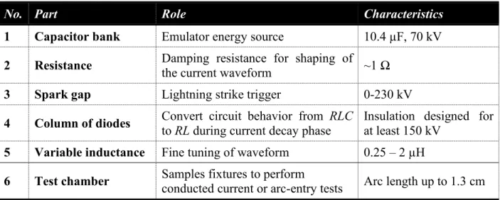
Table 2.1 : Direct and indirect lightning effects...6 Table 2.2 : Recommended practices for aircraft lightning protection from SAE... 10 Table 2.3 : Details of lightning current components, A through D...12 Table 4.1 : The constituents of the electrical circuit and their respective roles and characteristics
... 36 Table 4.2 : Comparison of different conducting and insulating materials... 41 Table 4.3 : Comparison of waveform parameters achieved by the emulator to those from of
standard waveforms...46 Table 5.1 : Manufacturing details and properties of conductive coatings utilized for lightning
strike protection...55 Table 7.1 : ‘Performance guide’ for use in conjunction with procedure for LSP testing...94
LIST OF FIGURES
Figure 2.1 : A time-lapse schematic explaining the mechanism of aircraft intercepted lightning... 5
Figure 2.2 : Typical current components of the standardized lightning waveform...11
Figure 2.3 : (a) Typical RLC circuit, and (b) Generated waveforms... 12
Figure 2.4 : (a) A crow bar circuit, and (b) Typical generated waveform...13
Figure 2.5 : Photographs and circuit diagrams of (a) Lightning impulse generator, Haefely Test AG., and (b) Lightning strike generator, University of Washington...15
Figure 2.6 : Scanning electron microscopy (SEM) images showing two key modes of lightning damage in CFRP: (a) fiber fracture and (b) resin pyrolysis... 17
Figure 2.7 : Damage analysis results obtained through hybrid techniques ... 17
Figure 2.8 : Raman spectroscopy study of nickel-coated SWNTs used as conductive fillers in bismaleimide–carbon fiber composites subjected to lightning strikes... 21
Figure 4.1 : Standardized lightning current waveform as described in SAE ARP 5412 [2]... 28
Figure 4.2 : (a) A-component test waveform as described in SAE ARP 1512 [2] and (b) Typical RLC circuit for emulation of lightning impulse... 29
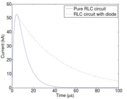
Figure 4.3 : (a) RLC circuit behavior: operation with diode in blocking mode, and (b) RL circuit behavior: operation with diode in conduction mode... 33
Figure 4.4 : Effect of the diode on the waveform produced by the RLC circuit...33
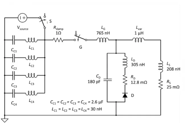
Figure 4.5 : (a) Electrical circuit, and (b) CAD model of the emulator; the numbered components are listed in Table 4.1... 35
Figure 4.6 : Schematic of variable inductance showing different inductance positions used in the study...37
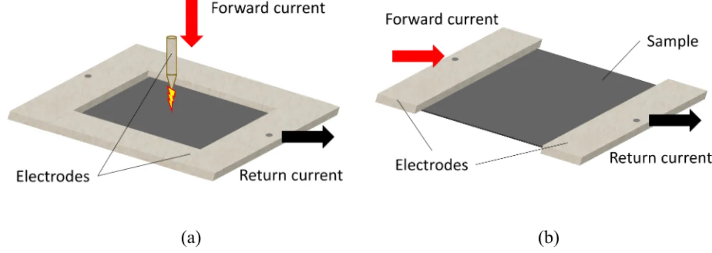
Figure 4.7 : Sample configuration for (a) arc-entry, and (b) conducted current tests... 37
Figure 4.8 : Detailed equivalent circuit of the lightning current emulator... 38
Figure 4.10 : Parametric study with variation of (a) Lvar(with RS=25 mΩ), and (b) RS(with Lvar=1
μH) ...39 Figure 4.11 : (a) Photograph of the actual emulator with inset showing the electrode
configuration in the specimen holder. (b) Electrical circuit of the emulator showing the control and measurement components; 1: high voltage supply (voltage multiplier), 2: high voltage switch, 3: voltage divider (for voltage measurement), 4: grounding rods (with discharge resistance), 5: main control unit, 6: oscilloscope (data acquisition and visualization), and 7: Rogowski coil (current measurement)... 41 Figure 4.12 : The oscilloscope image of a ~50 kA impulse waveform with test specimen
subjected to different non-destructive analysis; Sample: CFRP, test type: arc-entry, variable inductance position: middle. (Oscillogram axes was modified for improved clarity)... 43 Figure 4.13 : Impulse tests in a short-circuit configuration with varying peak amplitudes; Sample:
none, test type: short-circuit, variable inductance position: middle... 44 Figure 4.14 : Comparison of emulated waveforms with varying values of inductance with
scaled-down waveforms defined in SAE ARP 5412; Sample: aluminum plate, test type: arc-entry. ... 45 Figure 4.15 : Photographic (left) and ultrasonic C-scan (right) images depicting the damage
characteristics of CFRP panels subjected to (a) Scaled A-component impulse stroke of 40 kA (sample size = 30.5 cm × 30.5 cm) and (b) Full scale D, B and C* components in a single stroke (sample size = 22.5 cm × 22.5 cm)... 46 Figure 5.1 : Typical current waveform used for lightning direct current effects testing [5]... 53 Figure 5.2 : (a) Lightning impulse emulator; 1: capacitor bank, 2: damping resistance, 3: spark
gap, 4: column of diodes, 5: variable inductance, 6: test chamber; Inset: Sample holder showing ECF clamped under under an aluminum electrode frame (negative electrode) and copper striker (positive electrode) over its center, and (b) Filtered impulse current waveform for CFRP with estimated parameters...56 Figure 5.3 : Schematic of test setup for lightning continuous current emulation: 1: Computer with
Signal filters, 6: Current probe, 7: Specimen under test, 8: electrodes, 9: Infrared mirror; Inset: Schematic of test specimen used for ambient-current sheet resistance measurements 58 Figure 5.4 : Photographs of the coated composite panels after undergoing 40 kA lightning
impulse strike; sample size is 30 cm × 30 cm... 59 Figure 5.5 : Ultrasonic C-scan (time of flight) images of the coated composite panels after
undergoing 40 kA lightning impulse strike... 61 Figure 5.6 : Damage characteristics of the samples derived from ultrasonic C-scans: (a)
Maximum damage depth, and (b) Maximum damage depth...62 Figure 5.7 : Schematics of material design at the microstructural level for the three silver-based
LSP coatings: (a) Ag, (b) Ag-C and (c) Ag-P (The size and volume fraction of grain boundaries and conductive fillers are not representative of the true values)...63 Figure 5.8 : Damage behavior of (a) Ag showing Lichtenberg pattern [12], and (b) SF showing
extra-central damage; inset: magnified view of damage; sample size is 30 cm × 30 cm...64 Figure 5.9 : Voltage response of coated specimens to conducted continuous currents (charge
transfer: 200 C)...65 Figure 5.10 : Thermal images (maximum temperature) during continuous current test of (a)
Cu\Sn showing coating defects with a photograph of the specimen, and (b) Sn showing hot-spots near electrodes; The reflection from the composite rear which attained its maximum temperature approximately 2 s after the continuous current test is also shown. Specimen arrangement and scale are described in Figure 5.3 (Top- view of specimen holder). Part of the mirrors showing stray reflections has been masked for clarity... 66 Figure 5.11 : Snapshots from 40 kA lightning impulse strike on Cu\Sn continuous coatings
showing hot runaway coating fragments...67 Figure 5.12 : (a) Photograph and (b) Ultrasonic C-scan of ECF-clad CFRP showing surface
damage after subjection to zone II lightning... 67 Figure 5.13 : Sheet resistance of coated specimens from ambient current tests...69
Figure 6.1 : (a) Effect of sensitization parameters on silver deposition, (b) Effect of AgNO3:KOH molar ratio on silver deposition, (c) Effect of sintering parameters on resistivity of silver
coatings, and (d) Final microstructure of silver coating ...79
Figure 6.2 : (a) X-ray spectra of the silver coatings; sintering parameters: 120 °C, 6 h, (b) Dependence of the silver coating resistance on temperature, (c) Typical results from current injection tests on silver coated CFRP, and (d) Silver-coated CFRP specimen after peel adhesion tests...81
Figure 6.3 : Schematic of the process for producing selective area coatings of electroless silver 82 Figure 6.4 : Design illustrations for potential aerospace applications of continuous and selective area coatings... 84
Figure 7.1 : The Impulse strike emulator... 90
Figure 7.2 : Effect of variable inductance on impulse waveform...91
Figure 7.3 : Key electrical equipment for continuous current emulation...91
Figure 7.4 : Procedure for LSP testing with separate impulse and continuous current emulators.92 Figure 7.5 : (a) Specimen resistances measured during continuous current emulation, and (b) Quantification of damage suffered by test specimens subjected to lightning impulse currents with a peak amplitude of 40 kA...94
LIST OF SYMBOLS AND ABBREVIATIONS
a Radius of the wire
A Area
ARP Aerospace Recommended Practice
C Capacitance
CFRP Carbon Fiber-Reinforced Polymer
CNC Computer Numerical Control
CRIAQ Consortium for Research and Innovation in Aerospace in Quebec
δ Skin depth
Δ Electrical quantity defined as: R24(L/C
DMA Dynamic Mechanical Analysis
e Mathematical constant:2.71
EDS Energy Dispersive X-ray Spectroscopy EMI Electro-Magnetic Interference
EUT Equipment Under Test
FAA Federal Aviation Administration
FEM Finite Element Method
FRP Fiber-Reinforced Polymer
GFRP Glass Fiber-Reinforced Polymer
ICP-MS Inductively Coupled Plasma - Mass Spectroscopy IGBT Insulated Gate Bipolar Transistor
i, I Current
i0 Initial current
IR Infra-Red
ITO Indium Tin Oxide
k Probe correction factor
l Length
L Inductance
LG Variable inductance
LV Variable inductance
LSP Lightning Strike Protection μ0 Magnetic permeability of air
NASA National Aeronautics and Space Administration NDE/T Non-Destructive Evaluation/Testing
NSERC Natural Sciences and Engineering Research Council of Canada
π Mathematical constant:3.14
PEDOT:PSS Poly(3,4-ethylenedidxythiophene) polystyrene sulfonate
PLA Polylactide
q Charge
Q Heat
ρ Resistivity
r Radius of the RL loop
R (Bulk) Resistance
RD Damping Resistance
RS Sheet Resistance, Sample Resistance
RLC Resistance-Inductance-Capacitance
σ Standard deviation
SAE Society of Automotive Engineers
SEM Scanning Electron Microscopy
SHM Structural Health Monitoring
SWNT Single-Walled Nanotube
τRL Time constant of RL circuit
t Thickness, Time
t1/t2 Impulse form
td Pulse duration
tt Total duration
TGA Thermo-Gravimetric Analysis
USAF United States AirForce
V Voltage
V0 Initial voltage
VC0 Initial voltage in the capacitors
w Width
W Power
WiFi Wireless Fidelity
CHAPTER 1
INTRODUCTION
On an average, aircrafts are struck by lightning once an year [1, 2]; a dramatic discharge of electrical charges can have serious consequences to the structure, electronics, and also cause fuel-related accidents [1]. Fortunately, such mishaps have been rare owing to the excellent conductivity of the all-metal (usually aluminum alloys) bodies which form a Faraday cage and restrict the electrical currents to the exterior of the aircraft. Today’s polymer composite aircraft predominantly utilize metallic meshes and foils to compensate for their inferior electrical conductivity. Integration challenges (i.e. both during fabrication and repair), possibility of galvanic corrosion at carbon fiber-mesh interface [3] and increased weight (metal plus the accompanying resin/isolation layers for corrosion mitigation) are all issues associated with the above-mentioned lightning strike protection (LSP) materials. For these reasons, the aerospace industry is looking towards alternative materials and methodologies to achieve light-weight, externally applied conductive aircraft surfaces, a promising avenue being conductive films and coatings.
To realize a similar goal, industries and research groups from universities in and around the province of Quebec, Canada, collaborated through the COMP-502 project ‘Conductive surface films or coatings for composite structures’ to explore different electrically conductive materials for application as light-weight LSP technologies. This project was coordinated by the Consortium for Research and Innovation in Aerospace in Quebec (CRIAQ) and the Natural Sciences and Engineering Research Council of Canada (NSERC), and comprised of Bombardier Inc. (Aerospace), Bell Helicopter Textron Canada Ltd. and 3M Canada Company as industry partners and Polytechnique Montreal, McGill University and the Université du Québec à Montréal as partners for academic research. The project was structured to contain:
Three MATerial design and fabrication groups,
A mechanical INTegrity and environmental testing group, and An ELEctrical design and fabrication group.
This thesis appertains to the ELE group where the candidate’s research goal was to identify the most promising surface materials for their ability to effectively protect composite materials
against lightning strikes. This being the initial phase of the project, many different ideas for surface materials have been explored in parallel by the MAT groups. Lightning interaction with materials is a multi-physics phenomenon and thus electrical conductivity alone is insufficient to provide a complete picture pertaining to damage resistance. Simulation-based techniques cannot provide accurate results, especially when the material systems themselves are not well defined. Therefore, emulated lightning tests are continuously needed to evaluate and support the process of materials development. However, there are not adequate testing facilities, which, even otherwise is a very expensive. In this initial phase, testing with a moderately strong strike able to emulate the main characteristics of a lightning waveform is warranted and will suffice for comparison and development purposes within a practical time envelope. Test protocols involving characterization of lightning damage to coatings/substrate materials along one or several axes: visual, structural, thermal and so on, are required. This information will help tailor remedial measures to improve materials design and manufacturing (as/if required).
Thus, the candidate’s broad responsibilities consisted of:
Establishing low-cost test facilities to emulate lightning current waveforms in the laboratory, and
Testing and evaluating (damage analysis via non-destructive methods) the conductive coatings.
In addition to the above accomplishments, the candidate also pursued:
Extension of the application of the conducting coatings in the aerospace sector, beyond LSP. The work carried out to realize the above goals is presented in this thesis, which is divided into 8 chapters commencing with this introduction. Chapter 2 comprises of a review of pertinent literature. Chapter 3 defines the research objectives and the methodology employed to realize the same. It also briefly discusses the presented research articles and their coherence with the objectives. The key findings of this thesis were submitted to suitable peer-reviewed journals as three research articles. These are presented as Chapters 4, 5 and 6, and respectively report the lightning test equipment developed, lightning test results, and extended applications developed based on the principal research work. A general discussion summarizing the results of this research work is included in Chapter 7. Concluding remarks and recommendations are made in Chapter 8.
CHAPTER 2
LITERATURE REVIEW
Until recently, aircrafts were manufactured out of lightweight aluminum alloys. Now, the civil-aviation industry has been imbibing composite technologies for additional weight reduction and improved mechanical properties. A composite material “is a macroscopic combination of two or more distinct materials, having a recognizable interface between them” [4]. This entails that the constituents must be chemically distinct and physically separable in such materials. Composites can be designed so that one of the constituent materials forms a continuous phase and contains the other materials, then the continuous phase is called a matrix and discontinuous phase the reinforcement. The resulting engineering properties of the composite are intermediate between the absolute properties of the component materials and depend on the design of the combination. A well-known example of composites are fiber-reinforced polymers (FRP) employed in the aerospace industry. The fibers could be glass, carbon or aramid and so on and employed as reinforcements while polymers such as epoxy or polyurethane the binding matrix [5]. The adoption of composite technology, especially carbon-fiber reinforced polymer (CFRP) and glass-fiber reinforced polymer (GFRP), can be clearly witnessed in a number of structural components for the Boeing 787 aircraft [6]. Up to 50% of the 787’s structure is made up of composites.
On an average, every aircraft is struck by lightning once a year [1, 2]. Several accidents instill that safety in terms of lightning strikes cannot be compromised [1]. Aluminum and its alloys are excellent electrical conductors and form a Faraday cage protecting the structure and critical electronics from lightning effects for a safe journey. The electrical conductivity of polymer composites is far inferior to that of metals. For example, carbon fibers have a 1000 times higher electrical resistivity compared to metals [5] and epoxy is further resistant by many orders of magnitude. This means that in the event of a lightning strike, the enormous energy of the lightning arc cannot be dissipated or rerouted to a lower potential zone without serious damage to the structural material. From around 5% in 70s, the utilization of composites has today risen to over 50%. The percentage utilization of composites has witnessed a steep hike in the last decade. Thus, lightning protection is garnering special attention in the aerospace community.
Today, long-distance services are improving, however in parallel, with increased passenger numbers and new airports, a lot of airlines operate their fleet so that there are multiple stops on a given route. Frequent landings and take-offs imply that aircraft today spend more time at altitudes
with high probability of strike [1]. With the above reasoning coupled with the fact that it is the aircraft that trigger lightning 90% of the times [1, 7], one can expect the strike statistics to change. Secondly, the number of natural lightning strikes is also increasing due to global warming. A 12% increase in lightning events is expected for every 1 °C rise in temperature [8]. Lastly, today’s aircraft rely heavily on various technologies such as fly-by-wire, electronically controlled fuel systems, computer-based navigation, advanced digital avionics and so on. This reliance on electrical automation and technology increases the risk with indirect effects of lightning [9].
2.1 Lightning strikes to aircraft
2.1.1 Aircraft in lightning environment
Lightning is a sudden, high intensity electrical discharge that occurs as atmospheric charges try and neutralize. Lightning occurs approximately 8 million times per day [10]. The most common source of lightning are the Cumulonimbus clouds. The works of Benjamin Franklin [11], C T R Wilson [12] and many others have contributed in unraveling the nature of this phenomenon. But even today, the exact mechanism behind cloud electrification is unclear. References [13, 14] discuss the key theories for charge generation - collisions between ice crystals and graupels (snow pellets or “soft hail”), ion capture by falling “hydrometeors” in an electric field, etc. It has been found that clouds can have multiple discrete charge centers whose positions are above an altitude required for attaining freezing temperatures. Generally, clouds may exist from an altitude of 1 km from the earth surface, but the center of the negative charges found in the lower regions of the cloud will exist at around 3 km or above [15]. The three main kinds of lightning flashes [16] associated with clouds are cloud to earth lightning, inter-cloud lightning and intra-cloud lightning. Others include the cloud to sky sprites and ball lightning [17].
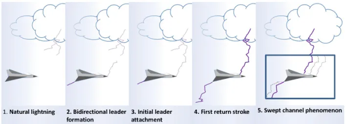
An aircraft can be a part of any of the three above-stated kinds of lightning, and in such a case the event is called “aircraft-intercepted lightning”. However, this is only a rarity and as often as 90% of the times, it is the aircraft that initiates the lightning [1, 7]. Based on aircraft design, points of extremities such as the nose or wing tips enhance the ambient electric fields around them [2]. This field intensification may lead to the formation of bidirectional leaders (see Figure 2.1(b), frame 2) thereby triggering a lightning [18]. Statistics compiled in the US Department of Transport sponsored ‘General Aviation Lightning Strike Report and Protection Level Study’ [19]
reveal that most of the lightning strikes occur during rain, however lightning in the absence of rain was also reported. With regard to aircraft position in the cloud environment, statistics state that the aircraft is prone to a maximum risk of lightning strike within the clouds. It has also been observed that it is during climb or descent that the frequency of strike is higher [1]. Usually, the air temperature between -5 to 0 °C and the altitude 9144 feet above mean sea level have been statistically prominent for lightning strikes to modern commercial jets [20].
Figure 2.1: A time-lapse schematic explaining the mechanism of aircraft intercepted lightning: 1.
A natural lightning occurs in the vicinity of an aircraft, 2. bi-directional leaders are generated from the extremities of the aircraft in response to the aggravated electric field, 3. initial leader attachment occurs, thereby establishing a conductive path, 4. the charge stored in the clouds is transferred through the conductive channel as what we see as a bright flash, and 5. as multiple charge centers in a cloud or near-by clouds are discharged, subsequent strokes occur. As the aircraft is moving, these strokes result in swept channel which show up as a series of hits over the
surface of the aircraft
2.1.2 Lightning interaction with materials
The physical effects of lightning due to current injection are called direct effects while exposure to electromagnetic fields results in indirect effects. These effects are listed in Table 2.1.
According to Kind and Feser [21], lightning strokes are “single, unidirectional impulse currents of short duration,” they “reach a peak value ipeakrapidly without oscillation and then decrease to zero”. The main characteristics of the waveform may be explained via the following terms.
Table 2.1: Direct [22] and indirect [23] lightning effects
Direct effects Indirect effects
Shockwave
over-pressures leading to
matrix cracking and fiber damage
Electromagnetic coupling
transient current and voltage inducement Arcing and sparking
fuel ignition & other fires
welding and roughening of movable parts
Structural IR voltages
Resistive heating melting and welding
resin evaporation & charring leading to burnouts, ply delamination
Bound charge secondary arcing
Dielectric breakdowns puncturing, splintering
Electrostatic pulses Magnetic force effects
deformations Electrical shocks
(i) Peak current, ipeak: The maximum value of current that is generated in a given stroke. The enormous currents (i) of lightning will also produce large voltages (V) unless their paths provide for low resistance (R). According to Ohm’s law:
.
iR
V (2.1)
These large voltages can then result in “flashes” between their paths and other objects, and must be considered with the same caution as the actual lightning strike.
(ii) (Maximum) rate of change of current, di/dt: The peak voltage produced in objects with inductive impedance (L) is different from that of those having resistive impedance. The governing law is then a combination of Oersted’s law, Faraday’s law of induction and the Lenz’s law. This case will see the voltage, V as:
. dt di L V (2.2)
(iii) Total charge, ∫idt: The amount of charge that each of the lightning components can transfer during a strike; particularly the C-component can amount to 200 C [24]. Power input, W, can be calculated as: , t Vq Vi W (2.3)
where q is the charge. This power input which determines the extent of heating and associated phenomena is proportional to the total charge transfer at the first approximation [13].
(iv) Action integral, ∫i2dt: This integral of current squared over time, with units A2s or J/Ω, is
connected to resistive or joule heating, which is the phenomenon of generation of heat in a (resistive) material when electric current passes through it. The amount of heat generated, Q:
.
2R i
Q (2.4)
In addition to the above, impulse form, t1/t2, time period, td, and total duration, tt, are also used to
define waveforms.
It is seen that electrical resistance (measure of opposition to flow of electric current) is a dominant electrical property governing the lightning interaction with materials. While electrical resistance depends on the shape and size of the material under consideration, it is the electrical resistivity (ρ) which is inherent to materials, and for simple geometries is measured indirectly from the resistance of the specimen as:
, l A i V l A R (2.5)
where, R is the bulk resistance of the specimen, A is the area of cross section of the specimen, and l is the length. The resistance itself is deduced from current (i) and voltage (V) measurements across the specimen.
The value of resistance for a bulk material can be obtained either from two-probe or the four-probe method. In the two four-probe method, the same electrodes are used to both inject a known value of current and measure the developed voltage, while separate sets of electrodes are used for these purposes in the four-probe method. The advantage of the four-probe approach is that the contact resistance is discarded from the measurements. When greater precision is required,
resistivity is measured using collinear, equally-spaced, 4-point probe system and consequently calculated as: , ) 2 ln( I k t V t RS (2.6)
where, RS is the sheet resistance of the sample, which is equivalent to the bulk resistance of a square sample, i.e., sample length is equal to its width. t and k are respectively the sample thickness and a correction factor that takes multiple parameters such as probe geometry and spacing, and sample thickness into consideration.
Resistivity also varies as a function of temperature. For metals, resistivity increases with temperature; this increase is taken as a linear function when away from the melting point.
Direct currents flow through the bulk of the material, however with increasing frequency, alternating current density shifts towards the surface of the conductor. Skin-depth, δ, of a material is defined as the distance from the surface where the value of current density falls to 1/e of that at the surface. In addition to frequency, skin-depth is influenced by permittivity and magnetic permeability of the material.
On the other hand, non-conducting materials such as GFRP are unable to transfer electric current and undergo dielectric breakdown. Dielectric strength is the minimum voltage at which dielectric breakdown occurs in the material [25]. For materials that may be exposed to lightning or other high voltage transients, a voltage impulse (1.2 μs/50 μs) may be used to test specimens. The impulse dielectric breakdown voltage is “the peak voltage that the wave causing breakdown would have reached had breakdown not occurred” [26].
2.1.3 Conductive materials for aircraft lightning protection
In order to build a Faraday cage for today’s composite aircraft, manufacturers employ either one or a combination of the following material technologies:
Metallic meshes and foils: Almost all meshes/foils available today take the form of stretched /
expanded products. This allows them to achieve a higher degree of protection in one direction which during layup is matched with the direction of airflow during flight. The order of thickness is many tens of microns for both classes of materials; although unlike meshes, foils require no
weaving and thus have lower projected thickness. More importantly, the absence of weaving stresses permits the use of very high purity materials (no alloying for strength) which translates into higher conductivity. Materials include: copper, bronze, nickel and phosphoric acid anodized aluminum. Wires made of these materials can also be woven into the standard fiber mat to make inter-woven wire fabrics for use in less-critical zones [27, 28]. Furthermore, prepregs incorporating metallic meshes are also available. The conductivity of the matrix of such prepregs has also witnessed an improvement due to the modification with certain additives.
Metalized fibers and fabrics: This list of products consists of carbon, graphite, glass, polyester
and other synthetic fibers coated with any one of nickel, copper, silver, gold, palladium, platinum or ITO (indium tin oxide) [29]. Further, hybrids in the form of multi-layered coating are also possible. Product range includes – chopped fibers, veils, and mats or even in the form of prepregs. The advantages of this class of materials are in easier handling and time-saving during fabrication.
Surfacing films and tapes: Surfacing films/tapes incorporate metallic screens and foils. The
advantage is the ease in handling, layup and improved quality of surface both before and after painting. The latest of classes is the ‘sprayable’ LSP materials, made by loading one-part epoxies with conductive particles. When nanoparticles are used standalone, without a binder, their coatings can also lead to better dispersion and coverage on the (ply) surface, and limitations with respect to matrix viscosity, reinforcement content and their distribution will no longer hold relevance [30]. Many new materials are under investigation: advanced materials such as carbon nanotubes [31, 32] and graphene [3] with their exceptionally high theoretical conductivity on one hand and equally competitive hybrids, for example, silver [33] and nickel-coated [30] carbon nanotubes, nickel and copper coated chopped carbon fiber [34] and so on are being investigated for potential application in LSP materials.
Lightning diverter strips: Diverter strips may be continuous metallic strips or segmented [35]
whose one end is grounded. Segmented strips take the form of a series of continuously-placed metallic buttons, bonded or riveted to a long plastic strip . The buttons could be round or take an elongated shape, but are separated by a short distance (hundreds of microns) so that they don’t form a electrical path under normal conditions. However when a strong-enough electric field is applied, the gaps between the buttons break down and help guide the lightning currents between
the point of strike and a conducting zone. Diverter strips are applied in regions of aircraft such as radome that cannot be covered in continuous conducting materials.
2.2 Laboratory emulation of lightning
The characteristics of lightning and the nature of its interaction with aircraft have largely been derived via areal experiments (i.e., in the sky) [36]. The NASA storms hazard program (1980-86,) the USAF-FAA lighting characterization program (1984-85, ‘87) and the French Transall program (1984, ’88) were the major research efforts where natural lightning was intercepted with special aircraft fitted with sensors and other processors. Today our understanding of aircraft-lightning interaction is developed enough that “in-service flight testing” like that applied to the first instances of composite application in the aerospace industry [37] are not required. Various ground-based testing methods have been devised that can ensure accessible, less expensive (compared to areal experiments), repeatable and safe emulation of lightning on custom samples.
2.2.1 Test standards and procedures
Aircraft need to meet stringent requirements in terms of quality and performance of their systems. On the lightning front, these requirements are set forth to mitigate both direct and indirect effects. Table 2.2 lists the recommended practices for testing to meet different government regulations.
Table 2.2: Recommended practices for aircraft lightning protection from SAE
Pub. Title Content Ref.
ARP5412 Aircraft lightning environment and relative test waveforms
Characteristics of lightning encountered by aircraft and resultant transients at electrical/electronic system interfaces
[38]
ARP5414 Aircraft lightning zoning Definitions and guidelines for location of lightning
strike zones on aircraft [39]
ARP5416 Aircraft lightning test
methods Techniques for testing of aircraft and their systemsfor simulated direct and indirect lightning effects [40]
LSP (direct effects) testing of aircraft can be categorized into two kinds. The first concerns the identification of lightning attachment points and thus establishing the zoning for the aircraft. This is achieved via high-voltage attachment testing on small aircraft or scaled down models of large aircraft/sections [40]. High voltage facilities are also used for the swept channel attachment tests.
The second category is the high current testing to study physical damage, and verify the ability of the material/component to withstand the large lightning currents. It is indeed important to consider zoning for this case because, the different current components or their combinations need to be utilized for testing different zones. Structural and component-level tests also utilize high-current facilities.
Different material types and or compositions may be employed based on threat level. Figure 2.2 and Table 2.3, from ARP 5412, describe the standard waveform of lightning. For lightning tests on materials, the current components are, as a standard, emulated sequentially in a single run. It can be observed that the A/D (peak) and C (rectangular) component are the two most distinct regions of the typical current component and thus are often used to study LSP materials for preliminary investigations [41-43].
Figure 2.2: Typical current components of the standardized lightning waveform [38] Table 2.3: Details of lightning current components, A through D [38]
Comp. Mathematical definition, t is time (s)
Charge transfer (C) or action integral (A2s)
Duration A I(t)=I0(e-αt– e-βt); I0= 218810 A, 2×10⁶A2s ± 20% ≤ 500 µs
α = 11354 s-1, β = 647265 s-1 (in 500 µs) B I(t)=I0(e-αt– e-βt); I0= 11300 A, α = 700 s-1, β = 2000 s-1 10 C ± 10% ≤ 5 ms C Squared waveform 200 C ± 20% 0.25 – 1 s D I(t)=Iα = 22708 s0(e-αt– e-1-βt, β = 1294530 s); I0= 109405 A,-1 0.25×10 6A2s ± 20% (in 500 µs) ≤ 500 µs
2.2.2 Design of lightning current emulators
The resistance (R), inductance (L) and capacitance (C) - RLC circuits are the established circuits for impulse generators [22]. A typical RLC circuit shown in Figure 2.3(a) could produce different types of waveforms as shown in Figure 2.3(b).
(a) (b)
Figure 2.3: (a) Typical RLC circuit [44], and (b) Generated waveforms [45]: (a) under-critically
damped, (b) critically-damped, and (c) over-critically damped
The conditions for producing each of these types of waveforms can be defined as follows [45]: a. Under-damped (oscillatory): 0R 2 L/C ,
b. Critically-damped (unipolar): R 2 L/C,and c. Over-damped (unipolar): R 2 L/C.
The unipolar waveform produced in an under-damped circuit however comes with disadvantage of low peak currents. Crow bar circuits such as the one shown in Figure 2.4(a) are utilized to overcome this disadvantage [44, 45]. During the operation of this circuit, the crow bar switch is engaged at the moment when the peak current is reached (voltage across crow bar is zero) to
short out the capacitors. As the energy from the capacitors at that moment would be stored in the (sample and crowbar) inductance, the decay times are increased and a unipolar pulse is produced.
(a) (b)
Figure 2.4: (a) A crow bar circuit [44], and (b) Typical generated waveform [45]
Energy for the lightning emulators can come either from capacitive or inductive storage systems, transmission line based storage devices, mechanical machines and accumulator batteries are other available sources. Large capacitor banks are the energy source in many emulator designs whether for full-scale testing [46] of the aircraft or laboratory tests on smaller components and test samples. While capacitors are known for their suitability for low-power charging, power amplification and long-term storage, inductive storage facilities have also been utilized in certain studies [47]. They can attain larger energy densities compared to capacitors. The switch usually takes the form of one of the following: (i) spark gap (air-gap) consisting of two conductive spheres/rods etc. (ii) a laser-induced trigger, or (iii) high-power diodes or even thyristors. A spark gap or diodes/thyristors, for instance connected to a capacitor bank can also have a say on the latter’s maximum voltage. The requirement for multiple pulses in a single test can be achieved by using multiple sources triggered by individual spark gaps [48] or a rail gap switch. Next, although the choice of sample depends on the experiment, as the resistance/load in the electrical circuit, it has a strong influence on the test waveform and pre-calibration of input circuit parameters may be required each time the sample type changes. Concerning the physical form of the generators, it is crucial to maintain a symmetric, coaxial configuration in order to maintain the high currents. As the current and voltage levels of test facilities increase, superior quality of materials and design, rating of individual components and insulating materials between such
coaxial lines and components would be required [42, 48]. Some emulators are illustrated in Figure 2.5
The lightning C-component is produced using a direct current (DC) source such as batteries [49]. The source can be operated individually or connected to the impulse emulator. Discharging techniques can be based on switches or insulated gate bipolar transistor (IGBT); this must be carefully executed from a hardware point of view so that these two emulators do not damage each other. Charging the DC source with the impulse emulator has been shown while using an IGBT [49].
Electrical parameters are measured/monitored via measuring resistors, Rogowski coils (induction effects), Hall generators, magneto-optic methods based on Faraday effect, photo-luminescent diodes and so on. Of these, the measuring resistors and Rogowski coils are popular in this field. Additional apparatus such as those to measure heating [50], luminescence/radiation during heating/explosions [47], mechanical impulse [51] to the samples may also be employed.
2.3 Characterization of lightning damage in the laboratory
Broadly, physical testing and modeling/simulation are the two approaches to study and understand lightning-induced direct damage in aircraft. Most commonly, physical testing involves emulating a lightning strike on composite panels with/without LSP materials. The extent of damage is then inversely proportional to the protection offered by the LSP material. In general, physical testing requires large investments of qualified personnel, money and time. This encourages many industries/agencies to adopt computer-aided modeling and simulation at various levels of product development. However, the complexity of understanding lightning material interactions limits the application of these techniques for direct effects evaluation and is not discussed further.
(a)
(b)
Figure 2.5: Photographs and circuit diagrams of (a) Lightning impulse generator, Haefely Test
AG. [52, 53], and (b) Lightning strike generator, University of Washington [52, 53] (Only non-standard components are identified for clarity)
At present, a hybrid of both approaches is more optimal in terms of utility and viability e.g., incorporating information from lightning tests into finite element method (FEM) models to verify mechanical integrity [54], acoustic shockwave parameters validations via instrumented impact tests [51] and so on.
2.3.1 Lightning damage to composite materials
Lightning interaction with materials manifests in a combination of electrical, mechanical and thermal effects among others. This interaction is complex, and three major modes of damage are usually observed in composite materials (see Figure 2.6).
Resin deterioration: When large amount of energy is injected into the composite system, the
bonds of the polymers undergo homolytic cleavage (which essentially is composed of single-electron reactions) [55]. Depending on the materials and their chemical surroundings two events can occur: (i) these decomposed products quickly react with other chemical species forming char, or (ii) vaporization preceded by quick loss in polymerization. Other aspects to be considered in this case are that of heat which is produced in the process of dielectric breakdown of air and Joule heating (of fibers and conducting matrices). Such a thermal decomposition of the polymer (resin) material has deleterious effects. Primarily, the resin is burned off and often the heat can damage the fibers also. In worst of cases, this can lead to a burn through. Another issue that worries engineers and safety experts is the noxious fumes that can emanate during such events [56, 57] .
Fiber damage: Three major reasons can be cited to explain fiber damage: (i) shockwaves due to
supersonic expansion of air around the lightning arc, (ii) Joule heating of the carbon fibers as they conduct the large lightning currents, (iii) the pressure exerted by hot pyrolysis gases which are entrapped between lamellae.
Delamination: Resin degradation results in the emanation of hot gases. The high pressure can
lead two events. One of them, as mentioned above, is the fracture of fibers. In the other case, the hot gases push through the ply lamellae and augment delamination. The area of delamination is thus usually larger than the area of resin deterioration. It has been shown that the pattern generated by the delaminations in the composites resembles the shape of “pairs of fans” propagating along the fiber direction in each of the lamellae [52].
2.3.2 Visual, non-destructive, mechanical and spectroscopic analysis of damage
Once a lightning strike has been emulated on the material under evaluation, the next step is to characterize the damage. Multi-technique characterization is often required for a complete understanding of the damage. Caution must be exercised to understand direct effects in view of factors such as the texture, surface features and even the finishing of the surface. Rough textures
may influence the attachment of lightning channel via dispersing its root at the material surface [58]. Similarly, even perforated structures may witness a distributed arc spread over an area, as it attaches to the ends of the fibers generated in the holes [59]. Painting the test component better mimics the real scenario [60].
(a) (b)
Figure 2.6: Scanning electron microscopy (SEM) images showing two key modes of lightning
damage in CFRP: (a) fiber fracture and (b) resin pyrolysis [61]
Figure 2.7: Damage analysis results obtained through hybrid techniques: Resin deterioration area
(binary image) is overlaid on an ultrasonic C-scan image of internal damage in a graphite/epoxy composite after an artificial lightning test (image rotated by 90°) [52]
Photography is possible at two instances, the first while testing the sample and secondly while studying damage. High-speed or long exposure modes of photography (with neutral density or polarized lenses) [62] are used in the first case. Such photography is used to study zoning, identification of specific lightning attachment points on a given sub-system [63] and direct effects such as arcing/sparking, an aspect critical to fuel tanks and allied systems [46, 64]. High-resolution cameras are applied to both record and study lightning-induced damage. The dual nature of the data, which is both qualitative (e.g., identification of damage modes) and allows extraction useful quantitative data (e.g. damage area), makes photography the key step in any characterization campaign.
Optical microscopy, categorized into dark/bright field, fluorescence and polarized light microscopy depending on the characteristics of the light source, is regularly employed for studying lightning strike damage in composites. Electron microscopy is used where high magnification and resolution are required. Spectrometric and/or diffractometry data from specific locations on the sample can also be obtained. For damage analysis via microscopy, it is suggested to ‘freeze’ the damage so that its characteristics are not altered due to handling or aging and to allow studies to be carried out at any point of time. Polymer encapsulation is commonly used for mounting specimens, sections/cut-outs of interest are encased in transparent epoxies. However, differentiation between the polymer matrices of the composites and that used for encapsulation may be taxing and result in errors. This issue can be resolved via introduction of fluorescent dyes into the encapsulating polymers. The result then will be similar to those presented by a liquid penetrant test, albeit inverted in contrast. Such a use of dyes comes handy in attempts to identify inter- and intra-ply arcing, matrix cracking etc. Some other kinds of defects may require the polarized light or the contrast differences provided by bright or dark fields to identify both their physical existence and origin. Ideas, for example, comparing scanning electron microscopy (SEM) images of the sample at position of arc strike and those of thermogravimetry (TGA) residue can hint the source of damage, which in this case is thermal degradation [30]. Other tools and techniques include photomultipliers for radiation measurement [47], profilometry to study surface roughness etc.
Visual inspection (and the conventional coin-tap [65]) helps locate damages and defects while microscopic examination reveals microstructural details. Non-destructive tests (NDT), on the other hand, are useful for macro and sub-macro-scale investigations. Non-destructive evaluation (NDE) ensures minimum alteration to the samples in the course of testing. It allows for the generation of a visual record or use ancillary systems to convert the outputs into one. This combined with advancement in electronics and computer science has led to data portability, application of artificial intelligence [66] for defect identification [67] & classification [68], pattern recognition, and so on, facilitating even the less-experienced practitioners.
Key non-destructive tests include ultrasonic testing, acoustic emission, thermography, radiography, X-ray computer tomography scan and so on. Almost all of these techniques are multi-purpose. For example, eddy current testing, which is based on electromagnetic induction can not only identify defects originating from impacts [69] but also help in measuring characteristics of materials such as coating thickness during wet spraying or the electrical conductivities of materials aimed at lightning strike protection [70]. Nonetheless, they all also have their limitations, which for eddy current testing is that it is applicable to conductive materials only.
NDT techniques applied to studying lightning damage in composites are focused on four aspects:
Profile – shape and directionality: define failure mode in composites Penetration – number of plies damaged: estimation of residual strength
Location – distinguish between damaged and undamaged (baseline) regions: choose samples
for post-lightning characterization
Extent – differentiate surface and internal damage: handy during repair.
Different combinations of lightning strike parameters and test materials yield equally different test results. One can compare and correlate specific damages in the material system to other changes such as mechanical properties [60]. For example, correlation of damage progression with impact-damage area and impulse currents through acoustic emission monitoring during compression tests [71] makes stress-strain curves even more information worthy.
Mechanical testing
(i) Determine the extent of damage in terms of changes in mechanical properties, and (ii) Estimate useful residual life for a given application.
Mechanical testing provides useful data in the form of stress-strain curves from which moduli, ultimate strengths, resilience or toughness can be derived and compared. However, proper normalization of data is important, e.g., impact depth with sample thickness or post-strike strength with pre-strike strength or that of the edge (unaffected zone) samples. Such a normalization must come from a scientific analysis of the data; data fitting (linear or power-law etc) must be carried out to decide on the best correlations presented by the data sets [60].
Mechanical impacts have a strong say on the compressive properties of the composites; residual strength may be reduced by up to 50% [72]. This makes compression-after-impact tests a more sensitive parameter to gauge the extent of such damage [29]. Flexural characteristics are ascertained through bending tests performed on rectangular coupons in the 3-point or 4-point configurations. Interestingly, these tests feature tensile and compressive forces on opposite sides of the test specimen. The lightning struck face is maintained in tension probably so that the test is as severe as possible with the damaged fibers in tension providing stress concentration (notch-effects) [73]. Some authors have also employed dynamic mechanical analysis (DMA) focusing on various parameters such as glass transition temperature related to the resin cross-link density [74]. The key advantage of DMA is its ability to detect low intensity thermal damage (degradation,) which cannot be easily detected by conventional non-destructive techniques.
Hybrid techniques are the current trend in the industry. In literature, one such technique was based on the use of built-in optic fiber strain sensors embedded into the material/components of the aircraft (for example, “the main spar of a test wing”) to monitor their behavior with respect to load. Further, information on the impulse and other forces exerted due the lightning arc may be computed. Such information can then be used during modeling and simulation assignments and also in the development of equivalent mechanical tests [64]. In another interesting set of studies, Chen et al. [75] investigated if an artificially damaged rudder could function effectively given the rigid structure principle applied to its manufacture. They fixed the rudder into an actual fin and, and conducted static tests with a network of actuators and sensors that confirmed the rudder was able to sustain their design loads
Spectroscopic tools
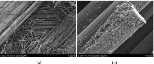
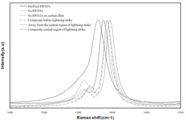
Spectroscopic tools yield valuable information on the chemistry and stability of materials. In the context of lightning strikes, changes in the chemical make-up of the coatings both in terms of composition and structure may be detected and cause-effect relationships derived. For example, while studying carbon fiber-bismaleimide composites that were filled with nickel-coated single wall nanotubes [30], the authors employed inductively-couples plasma - mass spectroscopy (ICP-MS), to study the affects of high currents and associated heating on the metallized nanotubes. In the same study, special attention was paid to the strain-sensitive G-band of the nanotubes through Raman spectroscopy. The authors compared positions of the G-bands before and after lightning strikes and found a peak shift which they attributed to the strain possibly generated as the “resin pulverizes and pulls the nanotubes along with it.” In another study involving nanotubes [76], it was observed from the EDS data, that nucleation of iron and titanium took place after carrying high current tests on composites. This was attributed to the destruction of the nanotubes at high temperatures that left behind the catalysts and abraded products from the sonicator tips.
Figure 2.8: Raman spectroscopy study of nickel-coated SWNTs used as conductive fillers in
bismaleimide–carbon fiber composites subjected to lightning strikes [30]
2.4 Summary of literature
Present day LSP research is shifting towards conductive coatings. The major advantage of the externally applied conductive solutions is that any shape and size can be easily covered with these materials. Further, lightning-induced damage will be confined to the exteriors of the structural material enabling quick and easy repair. However, two critical challenges remain to be resolved before these materials undergo a transition from laboratory technologies to commercial products. They are (i) good dispersion and homogeneity, and (ii) lower contact resistances between conducting particles. Therefore, metallic meshes and foils still form the benchmark in terms of overall sheet resistance. Testing of direct effects of lightning is critical to the certification of aircraft for protection against lightning strikes. The high current tests damage both the LSP material and the composite it is protecting. Photography and non-destructive testing are common damage analysis techniques. A study of the type and extent of damage can provide feedback on fabrication flaws and other high current material properties. While in the aircraft industry, such results are used to evaluate LSP materials and make choices depending on aircraft zoning, in the laboratory, this feedback serves for improving the process methodology of conducting materials under development. As for lightning emulation, separate systems to emulate lightning impulse and continuous currents have been used in many studies. Most impulse emulators are based on crow bar circuits, while batteries are used for emulating lightning continuous currents.
CHAPTER 3
RESEARCH OBJECTIVES, METHODS AND RESULTS
This doctoral research is part of a larger effort of the COMP-502 project to develop conductive films or coatings for aircraft lightning protection. This thesis work is directed at designing and building experimental test facilities. Necessary test protocols would be developed in order to employ these facilities to carry out a preliminary investigation into the potential of the newly designed coatings to offer lightning strike protection to aircraft structures. The test equipment and protocols conceived must allow for carrying out scientific studies on the interaction of the materials with experimental lightning in a time-bound and cost-effective manner. At the same time, it is also envisaged to explore other applications of the test facilities/methods and materials by expanding upon the research efforts and available laboratory infrastructure.
3.1 Research objectives
The specific primary objectives of this thesis work are:
Objective 1: To establish screening-level lightning test facilities
Conceive, design and build an ‘impulse strike emulator’ to generate micro-second-range currents of up to 40,000 A, and a ‘continuous current emulator’ to generate sub-second-range steady currents of up to 500 A conforming to the SAE standards [38], and demonstrate their functionality.
Objective 2: To execute lightning strike tests on conductive coatings and damage analysis thereof
Subject conductive coatings realized within the scope of COMP-502 project to lightning currents using the impulse and continuous current emulators realized through Objective 1, and study the damage protection that the conducting coatings (material design schemes) offer to underlying CFRP through non-destructive methods.
In addition to these, a secondary objective was pursued:
Objective 3: To explore ideas to expand the application of test facilities, methods and/or materials
![Table 2.1: Direct [22] and indirect [23] lightning effects](https://thumb-eu.123doks.com/thumbv2/123doknet/2344434.34561/26.918.139.777.125.629/table-direct-indirect-lightning-effects.webp)

![Figure 4.2: (a) A-component test waveform as described in SAE ARP 1512 [2] and (b) Typical](https://thumb-eu.123doks.com/thumbv2/123doknet/2344434.34561/49.918.118.804.425.686/figure-component-test-waveform-described-sae-arp-typical.webp)