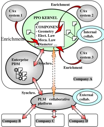
Enabled virtual and collaborative engineering coupling PLm system to a product data kernel
Texte intégral
Figure


Documents relatifs
Nous présentons dans cet article un modèle PLM pour la gestion des informations du produit tout au long du cycle de vie du produit et intégrant les
Centralized approaches used to treat the problem of integrated design of the product and its supply chain generate complex mathematical models, we adopt an approach
PLM facilitates project monitoring and mature objects sharing PLM supports structuring of new product development process.. PLM relies on content based
Google+ solutions for Framework of Informal Communication: Google+ is supporting following parts of FOIC: Support relationship development with “Circles”, encourage infor-
The academic center is also aiming at providing software tools installation and IT support to the member schools and services as the IT hub that all the
Based on an empirical application, the paper describes a methodology for evaluating the impact of PLM tools on design process using BPM techniques. It is a conceptual
The Asset Information Management, organized through the Product Structure and the Configuration (Management) Views is the backbone of the Building/Infrastructure
Indeed, by integrating the logistics constraints in the early stages of product development, this will avoid additional costs and time waste caused by a product unsuitable for
