Science Arts & Métiers (SAM)
is an open access repository that collects the work of Arts et Métiers Institute of
Technology researchers and makes it freely available over the web where possible.
This is an author-deposited version published in: https://sam.ensam.eu Handle ID: .http://hdl.handle.net/10985/9414
To cite this version :
Inigo TERREROS, Ivan IORDANOFF, Jean-Luc CHARLES, Dominique COUPARD, Serge TCHERNIAEFF - Discrete element method, a tool to investigate complex thermo mechanical behaviour: application to friction stir welding - Discrete element method, a tool to investigate complex thermo mechanical behaviour - Vol. 2, n°1, p.573-576 - 2009
Any correspondence concerning this service should be sent to the repository Administrator : [email protected]
DISCRETE ELEMENT METHOD, A TOOL TO INVESTIGATE COMPLEX
THERMO MECHANICAL BEHAVIOUR: APPLICATION TO FRICTION
STIR WELDING
I. Terreros
∗, I. Iordanoff, J.L. Charles, D. Coupard, S. Tcherniaieff
Arts et M´etiers ParisTech, Bordeaux1, LAMEFIP Esplanade des Arts et M´etiers, 33405 Talence,
FRANCE
URL: www.lamef.bordeaux.ensam.fr
ABSTRACT: In material forming or cutting, the contact zone between the tool and the working piece is often very
difficult to analyse because of diverse local phenomena. In the special case of FSW, a specific difficulty is the study of material mixing. In this work, the Discrete Element Method is applied as a tool to understand/propose/confirm physical scenarii involved in FSW process. A simple micro behaviour law that takes into account thermal, mechanical and material aspects is proposed and a two dimensional simulation based on this law is presented. The first results show qualitatively good agreement with real nuggets observations. One of the main advantages of DEM approach is the simplicity of the local input law compared with laws proposed at the continuous media mechanics level. Nevertheless, numerical aspect must be improved to carry out three dimensional simulations with reasonable calculation times.
KEYWORDS: Discrete Element Method, Friction Stir Welding.
1
INTRODUCTION
Friction Stir Welding (FSW) is a process invented at The Welding Institute (TWI) in the early 90’s. This process allows to join metals without fusion or filler materials. The welds are created by the combined action of frictional heating and mechanical deformation due to a rotating tool. At the present time the approach used to simulate FSW process are based on the Finite Elements Method (FEM) or on the Finite Differences Method (FDM) [1–3]. With those methods it is possible to simulate temperature fields [1–3], strain and residual strain fields [1, 2], heat source distribution, plastically-deformed zone and material flow while looking at deformation velocities [3]. We can also carry out simulations of the material flow using a fluid-mechanics based approach [4].
Despite the efforts done, to achieve an accurate simulation of material flow when it is between a solid state and a “slurry” state is still a delicate problem to manage with classic FEM. A possible suggestion is to use the DEM for the modelling, because of the exceptional skills of this method to carry out calculations of solid flows. There are works that demonstrate the validity of DEM to simulate and understand wear problems (in this field the difficulty to simulate the flux has been always a big challenge) like [5–8], among others.
∗Postal address: Pio XII, 1, 5C, 01400, Laudio, Araba, Spain. Phone:
+34 670 749 016. e-mail: [email protected]
2
NUMERICAL TOOL
2.1 GENERAL DESCRIPTION
The method described is based on smooth particle dy-namic method. The material is considered as a set of dis-crete spheres that move under a force field. The forces are contact forces to simulate multi-body interactions. Their magnitudes depend on a thermomechanical law which will be briefly described in next paragraphs. Particle movements are calculated using an explicit algorithm to integrate the dynamic Newton law.
It is vital to remember that each sphere doesn’t represent any kind of particle, but all the spheres as a whole repre-sent the behaviour of the material.
2.2 THERMOMECHANICAL LAW
As it is said above, the magnitude of contact forces is given by a thermomechanical law. First of all mechan-ical aspect is described, then thermal aspect, and finally a description of how mechanical and thermal aspects are linked will be given.
2.2.1 Mechanical part
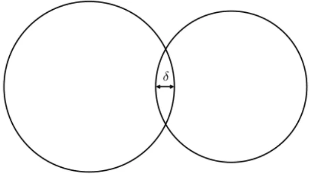
The particles’ (spheres in this study) interaction laws de-fine micro mechanical properties of the material. Every particle is subjected to contact force. This force acts only when two particles geometrically interact and it is divided into three parts: repulsion, adhesion (both are energy con-servative) and energy dissipation. Geometrical interaction δ allows the force calculation (Figure 1).
Figure 1: Geometrical interaction
• Repulsion is represented by a linear spring, whose stiffness is K. Repulsive force Fris:
Fr= K · δ (1)
• Adhesion has been simplified to a parameter γ which depends on particles’ temperature and accumulated displacement, γ = γ(T, U ). Relationship between γ, T and U is given in the section 2.2.3.
Fa= γ = γ(T, U ) (2)
• The energy dissipation in the contact is due to the damping force written as:
Fd= 2αpK · Mij· ˙δ (3) Where α id the damping coefficient (<1), ˙δ the im-pact speed and Mij the equivalent mass of the
con-tact.
The sum of the interaction forces is:
Fcontact= −K · δ + γ − 2αpK · Mij· ˙δ (4)
2.2.2 Thermal part
For the thermal part, model proposed by Richard et al. [6] has been implemented. However, some modifications to reach the purpose of modelling FSW process have been carried out. The thermal analysis is divided in two parts, heat creation and heat diffusion.
It is supposed that all the dissipated mechanical energy is transformed into thermal energy. Following the model of Richard, created thermal power is described like:
Qij = 2αpK · Mij· ˙δ2 (5) Assuming that heat is equally distributed between parti-cles i and j, the temperature rise of each particle because of thermal energy creation in∆t time interval is described by the following equation:
dTi= 0, 5 · Q ij∆t
ρicpiVi
(6)
At the moment of analysing heat diffusion, one assump-tion that differs from reference [6] is taken:
• The transmission surface between two spheres is sup-posed to be4R2
m(a2Rm× 2Rmsquare), where Rm
is the average radius of spheres, instead of the contact surface between both of them.
This assumption is closer from a continuum medium like FSW than hypotheses from [6], which try to describe a real granular field.
Then, the temperature rise of a particle is: Ti+= Ti−+
X
j
dTij+ (7)
Where Ti+is the temperature of a particle i at the moment t+ ∆t, T−
i is the temperature of the same particle at time
t and dTij+is the thermal contribution of each j particle to
i during∆t period.
From the viewpoint of discrete elements dTij+ is defined as: dTij+=4λijRm∆t(T − j − Ti−) ρijcpijVij (8) Where ρij, cpij, Vij and λij are the equivalent density,
equivalent heat capacity, equivalent volume and equiva-lent conductivity of particle i respectively.
Mixing equations 7 and 8, the equation that explains the temperature rise of particle i due to contact with the j par-ticles around is:
T+ i = Ti−+ ∆t X j 4λij ρijcpijVij · R m(Tj+− Ti−) (9)
2.2.3 Coupling of mechanical and thermal aspects
Once described thermal and mechanical parts, the mi-cromechanical law which links both of them will be ex-plained. The following analysis is based on Aluminium alloy Al 2017-T451.
This analysis micro-structural changes due to temperature and displacement. When material’s temperature rises, the precipitates that harden it disappear and mechanical prop-erties of material become weaker. Moreover, the hardest material is located near the trajectory of the pin of the tool (nugget), that is, the most displaced material which has the smallest grain-size.
Figure 2: Grain-size of raw material and nugget
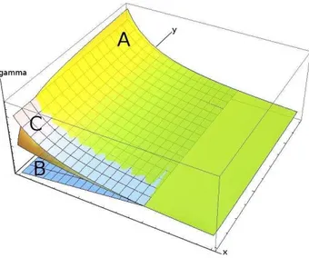
So, a relationship among material’s temperature cycle, grain size, displacement and hardness can be established. Having in mind those ideas, a surface that describes the cohesion between particles depending on the cycles men-tioned above has been created. The curve A from Figure 3 describes the first approach to that surface.
Figure 3: Adhesion forces
In axes x and y temperature and displacement are shown respectively. The third axe represents the hardness. The adhesion force of the contact between two particles is taken from this graphic and it is supposed proportional to hardness.
There are two surfaces apart A, which describes the law mentioned before. The surface marked as B represents the adhesion force between two particles of different plates and the other surface, marked as C, represents the adhe-sion between two particles of raw material of the same plate. Initially all the contacts between particles are classed in one of those two surfaces. Cohesion in the con-tact of particles of different plates will be null if they are cold, independently of the displacement. Nevertheless, cohesion will rise with the temperature until this curve crosses with A. From this moment the contact between the two particles won’t be described by B curve but by A. The same happens with C. Equal material’s particles’ co-hesion will be inversely proportional to the temperature until the temperature reach a limit. Here again we pass to the other curve to modell the adhesion force. The main idea behind that behaviour law is that adhesion decreases with temperature and increases with displacement. The results of the modelling of FSW with the proposed micromechanical law show qualitatively good agreement with real nuggets observations, as it will be shown in sec-tion 3.
2.3 NUMERICAL INTEGRATION
A Verlet velocity algorithm is chosen to integrate the ve-locities and new positions of spheres over a small time step∆t while accelerations have been calculated thanks to Newton laws described above [6, 8].
2.4 GEOMETRY AND BOUNDARY
CONDI-TIONS
For this work simulations with a two dimensional model have been carried out. The two walls surrounding the field
are fixed and they are at ambient temperature.
3
RESULTS
3.1 MECHANICAL PROPERTIES
Figure 4 shows experimental hardness of Al 2017-T451 across the weld at the top and a cross section taken from the results of the simulations carried on at the bottom. The meaning of coloured parts will be explained in the next paragraph.
Figure 4: Comparison of hardness & cohesion
Figure 5 shows the cohesion among the spheres after the simulation. There are three different areas divided by colours: Blue coloured spheres have the cohesion of raw material, cohesion is lower among spheres coloured in green and higher among those in red.
Figure 5: Cohesion
Numerical simulation is qualitatively in accordance with experiences. The center of the weld is harder than raw ma-terial an there are two bands composed by weaker mama-terial surrounding it.
3.2 THERMAL PROPERTIES
Simulated temperature contours have at the beginning good agreement with works like [2] and [9]. Neverthe-less, the current model has problems to dissipate heat, and temperature fields have tendency to have parallel isotherm lines, as shown in Figure 6. This problem may be solved with the solutions proposed in section 4.
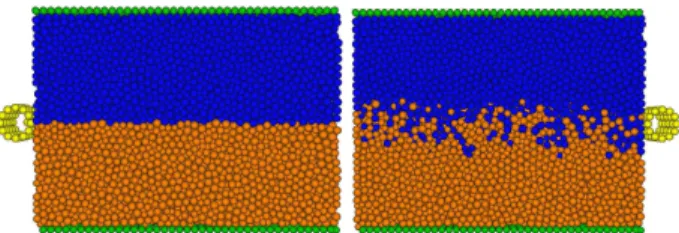
3.3 MATERIAL MIXING
The Discrete Element Method allows also to see how ma-terials of both plates are mixed while tooling. Figure 7 is an example of that. The field before tooling is shown in the first picture and second one represents the field after the process.
Figure 7: Material mixing
4
CONCLUSIONS AND PERSPECTIVES
Looking at the results one can conclude that:
• Discrete Element Method models qualitatively good FSW process as similarities between real and exper-imental hardness, weld characteristics and tempera-ture fields have been obtained.
• It is necessary to develop thermal boundary condi-tions because in the present work heat is evacuated only through two walls and this is not realistic. • The proposed micromechanical law must be
vali-dated.
• Calculation time must be reduced.
In order to reduce the calculation time, a combination among Finite Element Method, Dynamic Discrete Ele-ment Method and Static Discrete EleEle-ment Method is pro-posed. Effectively, FEM allows us to calculate rapidly thermal effects in areas where the movement of particles is always insignificant; the current dynamic DEM in ar-eas where particles’ movement is being important can be used; finally a static DEM which doesn’t search contacts among particles in areas where movements are negliable can be used. In fact, 80% of calculation time is spend in searching contacts, and may be reduced using this method. In Figure 8 we can see a schematic draw of this method.
REFERENCES
[1] Ch. Desrayaud, P. Heurtier, D. Allehaux, and F. Montheillet. Thermomechanical and
Figure 8: Proposed method
microstructural modelling of the Friction Stir Welding process. In 5th International Friction Stir
Welding Symposium, Metz, France, September 2004.
ISBN 1-903761-04-2.
[2] R.W. McCune, H. Ou, C.G. Armstrong, and M. Price. Modelling Friction Stir Welding with the Finite Element Method - a comparative study. In 5th
International Friction Stir Welding Symposium, Metz, France, September 2004. ISBN 1-903761-04-2.
[3] F. Palm, U. Henneb ¨ohle, V. Erofeev, E. Kerpuchin, and O. Zaitzev. Improved verification of
FSW-process modelling relating to the origin of material plasticity. In 5th International Friction Stir
Welding Symposium, Metz, France, September 2004.
ISBN 1-903761-04-2.
[4] P. Heurtier, M.J. Jones, C. Desrayaud, J.H. Driver, F. Montheillet, and D. Allehaux. Mechanical and thermal modelling of Friction Stir Welding. Journal
of Materials Processing Technology, 171:348–357,
February 2006.
[5] I. Iordanoff. Mod´elisation du Comportement Tribologique des 3e Corps Solides et Gazeux.
Laboratoire de M´ecanique des Contacts et des Solides LaMCoS-UMR CNRS / INSA 5514 INSA de Lyon, pages 31–51, 2004.
[6] D. Richard, I. Iordanoff, M. Renouf, and Y. Berthier. Thermal study of the dry sliding contact with third body presence. ASME Journal of Tribology, 130, 2008.
[7] B. Seve, I. Iordanoff, and Y. Berthier. Using Discrete Models to Simulate Solid Third Bodies: Influence of the Inter-granule Forces on the Macroscopical Behaviour. Tribology series, 39:361–368. [8] I. Iordanoff, A. Battentier, J. Neauport, and J.L.
Charles. A Discrete Element Model to Investigate Sub Surface Damage due to surface polishing.
Tribology International, 41:957–964, November
2008.
[9] X.K. Zhu and Y.J. Chao. Numerical simulation of transient temperature and residual stresses in friction stir welding of 304l stainless steel. Journal of
Materials Processing Technology, 146:263–272,
![[PDF] Cours Bases de données MySQL et php | Formation informatique](data:image/gif;base64,R0lGODlhAQABAIAAAP///wAAACH5BAEAAAAALAAAAAABAAEAAAICRAEAOw==)