OATAO is an open access repository that collects the work of Toulouse
researchers and makes it freely available over the web where possible
Any correspondence concerning this service should be sent
to the repository administrator:
[email protected]
This is an author’s version published in:
http://oatao.univ-toulouse.fr/27236
To cite this version:
Martinez, Mayerling and Fleurier, Gwendoline and Chmelík, František and
Knapek, Michal and Viguier, Bernard
and Hug, Eric TEM analysis of the
deformation microstructure of polycrystalline cobalt plastically strained in
tension. (2017) Materials Characterization, 134. 76-83. ISSN 1044-5803
TEM analysis of the deformation microstructure of polycrystalline cobalt
plastically strained in tension
Mayerling Martinez
a,
.
, Gwendoline Fleurier
a, Frantisek Chmelfk
h,
Michal Knapek
b,
Bernard Viguier
C,
Eric Huga
a Laborotclt< de Crlstallogrq,hie et Sdenus des Matériawr, Nomnndie Universlti, CNRS UMR 6508, 6 Boulevard Marécho! Juin, 14050 Cae11, Pranœ b Charles l.fnlvm4y, Facu1ty of Mathematks and Physks, D,partment of Physks of Materials, Ke Karlovu 5, PrOIJle 2 12116, Czedt .Republic c ClRIMAT, lJnivemJi de Toulouse, UPS-INP-CNRS, INP/P.NSIACET, 4 allie P.mih Monso-BP 44362, 31030 Toulouse Cedex 04, France
ARTICLE INFO
ABSTRACT
Keywords:
Hexagonal close packed structure Dislocations
Twlnnlng
PolycrystallJne cobalt
Transmlsslon electron mlcroscopy
The micrœtructure evolution of hexagonal close-packed cobalt at different stages of work han:lening bas been studied. The deformation microstructure of polycrystalline samples upon a tension test was investigated by n-ansmission Electron Micrœcopy (TBM). Corresponding straining mechanisms were also identified by acoustic emission measurements. It was shown that dislocation glide is the predominant deformation mechanism during the first stage of plastic deformation, while twinning becomes the prominent strain accommodation mechanism in the later stage. A detailed TEM study using electron diffraction allowed identifying different types of twins activated during tensile testing. Four single twinning modes were identified, from which two types correspond to tensile strain and two types to compressive strain (with respect to the c direction), double twins were also observed. A relative importance of various systems is estimated and it is shown that the vast rnajority of twins correspond to the {10I2j twinning system.
1. Introduction
Deformation mechanisms in hexagonal close packed (hq,) metals are typically characterized by two contributions: dislocation glide and deformation twins. During plastic deformation, different work hard ening stages can be distinguished: at the beginning, hexagonal metals deform by gliding, and then the deformation is assisted by twinning. The dominant slip system in hep metals depends on the unit œlls parameters (c/a ratio) and on the values of the critical resolved shear stress for the different slip systems. Important role is played by the stacking fault energy associated to basal, prismatic, and pyramidal planes, as well as by the elastic constants [1]. For titanium, beryllium and zinc, the principal slip system is the prismatic {1010)(1210) one, while for magnesium and cobalt it is the basal {0001)(1120) one. Al though prismatic slip is the primary slip mode in zirconium and tita nium, both pyramidal and basal slip systems have been observed, as well. Basal slip dominates in magnesium, but prismatic system can be observed in single crystals and pyramidal slip systems were reported in literature as activated by elevated temperature or higher stresses. On the other hand, the only slip mode commonly observed in cobah is the basal slip [2 6].
Because of the limited number of slip modes in hep lattiœ, twinning
represents an important ahernative for plastic deformation. Twinning in the {10!2} planes is the predominant mode at room temperature and is operative in ail hep metals, because the twinning shear magnitude of titis mode is the lowest [2]. Other twins, such as {l0il} and {10!3} have been observed in Mg or Mg alloys [7 9], while {1122} and{ltll} twins have been reported for titanium and zirconium [10,11]. The shape of deformation twins is influenced by the twinning shear. When the shear is small, as is the case of {1012} twins, the twin has a wide lenticular shape, since the twin boundary can deviate from the twinning plane without greatly increasing the twin interface energy. When the shear is large, the twins formed are narrow and have essentially parallel boundaries [2].
Among all
hep metals, cobalt and magnesium have the c/a ratio
close to the idealJ8ff
value. Cobalt has been much Jess studied and can be of particular interest because it exhibits a much higher melting point and very low stacking fault energy when compared with other hep metals [12]. literature regarding the general mechanical behavior of polycrystalline cobalt is scarœ and dates typically back to 1960s. Sorne studies were dealing with temperature effect in mechanical properties [13] or deformation twinning [14 16]. Others works conœm the de formation of single crystals [17] or thin filins [18]. Studies dealing with straining of polycrystalline cobalt appeared recently, but those are • Correspondlng author at: Laboratoire CRlSMAT, Enslcaen, Université de Caen, CNRS, 6 Bd Maréchal Juin, 14050 Caen, France.E-mail ad<Fes:s: [email protected] (M. Martlnez).
hardening rate θ = dσ/dε was then extracted from the true stress (σ) true strain (ε) curves allowing the identification of strengthening stages. To analyse deformation mechanisms in different work hard ening domains, mechanical tests were interrupted in the different stages of strengthening.
Acoustic Emission (AE) has proven to be a useful diagnostic tool and many metallic materials, in particular magnesium single crystals[27] and Mg based polycrystalline samples[28], were extensively studied using this technique. As cobalt is crystallographically similar to mag nesium, the AE technique, widely used in Mg studies, was employed in this study to characterize and understand the deformation processes. As far as we know, it is thefirst study of Co by this technique. The AE response was monitored using a computer controlled PCI 2 device (Physical Acoustic Corporation, PAC) operating in the waveform streaming mode (the AE signal parameters, such as counts, amplitude or duration, as well as a complete, non parameterized AE signal are stored during the recording). The AE signal from the sensor was pre amplified with a gain of 60 dB. A broadband PAC transducer was mounted on the specimen by means of a wooden clip and a silicon grease.
Samples in different hardening stages were examined in a Transmission Electron Microscope (TEM). Conventional bright field images were made with a Jeol 2010 operating at 200 kV. Samples for TEM observations were prepared by mechanical polishing until about 100μm thick and then electropolished by the twin jet method in a Struers Tenupol5, with an electrolyte consisting of 90% glacial acetic acid and of 10% perchloric acid at a voltage of 50 V.
3. Results
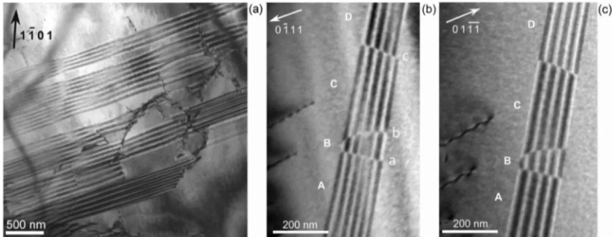
The initial microstructure of annealed polycrystalline cobalt is characterized by the presence of numerous stacking faults, some iso lated dislocations and dislocations grouped within small tangles (Fig. 2a). In the hcp lattice, three different types of stacking faults are possible, all lying in the basal plane: two intrinsic faults (I1 and I2) and one of extrinsic character (named E)[29]. The study of polycrystalline cobalt indicates that these defects are present as separated monolithic planar faults or as segmented stacking faults. These defects are present in cobalt also after deformation, as depicted inFig. 2b, c. The contrast analysis performed on isolated stacking faults such as the ones shown in Fig. 2a indicates that they are I1type intrinsic stacking faults. A similar contrast analysis was attempted on segmented stacking faults, as ex emplified onFig. 2b and c, with a +g/−g imaging of the same defect. These observations reveal that the fringe contrast is reversed upon each
Fig. 1. EBSD analysis of polycrystalline cobalt: (a) distribution of hcp and fcc phases and (b) corresponding polefigure showing the basal {0001} texture of the hcp phase.
mainly related to nanocrystalline samples [19], thin films [20], and sometimes are focused exclusively on the study of twinning modes [21 25]. So far the only thorough report describing mechanical beha vior of polycrystalline cobalt was published by Sanderson [26]. This author shows by metallographic observations, and using replica tech niques, that basal dislocation glide is a dominant mechanism at the beginning of plastic deformation while for large strain deformation twinning plays a significant role.
The aim of the present study is to provide a global approach of deformation microstructures in polycrystalline cobalt using transmis sion electron microscopy, and to give an overview of plasticity me chanisms in hcp phase during different stages of work hardening. Moreover, acoustic emission was used in the course of the straining process, as it yields information on the dynamic processes, such as dislocation slip or twinning, involved in the plastic deformation. Materials and experimental methods are presented in the second part. Experimental results in the third part focus on the deformation me chanisms in gliding and twinning stages, respectively. A special em phasis is put on the study of twinning, including statistics of the dif ferent twinning modes. Finally, the fourth part of the paper presents a discussion of the microstructural observations and a statistic analysis of the twin mechanisms operative in cobalt.
2. Experimental 2.1. Materials
Rolled sheets of polycrystalline high purity cobalt (99.9 wt%), 0.5 mm thick, were used as a starting material. The as received material was annealed under secondary vacuum at 1100 °C for 1 h. The analysis by Electron Back Scatter Diffraction (EBSD) coupled to a Scanning Electron Microscope (SEM) indicates an average grain size of around 11 μm and presence of about 8.5% of untransformed face centered cubic phase (Fig. 1a). The EBSD analysis also shows the typical basal {0001} texture present in rolled hexagonal metals (Fig. 1b).
2.2. Mechanical and Microstructure Investigations
Monotonous tensile tests were performed at room temperature on dog bone shaped samples with a gauge section of 20 mm in length and 10 mm in width at the strain rate of 2 × 10− 4 s− 1. The tensile axis was set parallel to the rolling direction of the sheet. Strain measurements were achieved by a traditional clip on extensometer. The work
crossing of the partial dislocations incorporated in the fault ribbon, see black/white outer fringes in A C and B D segments. Similar config uration was reported in[29], with a single partial crossing the stacking fault and leading to the same fringe contrast. The situation is somehow more complex here with the presence of three partial dislocations on the same fault ribbon, labelled a, b and c inFig. 2b. Imaging of the defect with different diffraction vectors shows that partials a and c have the same Burgers vector, different from that of partial dislocation b. A detailed analysis of such defect configuration requires further work and the use of TEM image simulation.
3.1. Plasticity Mechanisms in Polycrystalline Cobalt
Three distinct stages can be distinguished from the true strain true strain curves (Fig. 3(a)), as shown also in our previous study[30]. The first one is related to the NonLinear Elasticity (NLE) of cobalt and is not studied here. The others two, labelled A and B in the following,
represent the work hardening stages traditionally encountered in hcp structures. The deformation microstructure in these two stages was studied by TEM. Samples were deformed up to different strain levels: up to around 0.8% for samples in the stage A and up to around 4.1% for samples in the stage B. These levels are located in the middle of each deformation stage.
Strain hardening rate of the sample loaded in tension and the AE signal parameters recorded during the test are shown inFig. 3(b) and (c). The AE signals appear already in the elastic stage of tension, sug gesting that purely elastic behavior is not present and microplasticity takes place already in the beginning of straining. This observation is in line with many studies on Mg based alloys and is typically attributed to a low value of critical resolved shear stress of basal slip in these ma terials[28]. The parameters (counts and amplitudes) of the acoustic emission events exhibit their maxima at the onset of stage A of plastic deformation. This is caused by a massive dislocation motion and mul tiplication (which are known to be an efficient source of AE[31]). As a
Fig. 2. Stacking fault microstructure in polycrystalline cobalt: (a) General view showing stacking faults and dislocations in non-deformed sample (after annealing state); (b) and (c) some stacking faults are segmented by the incorporation of partial dislocations which induces a reversing of the fringe contrast, as revealed by the +g/ g imaging (observations made in deformed cobalt).
Fig. 3. (a) Typical work hardening curve for polycrystalline cobalt and corresponding tensile curve in insert. (b) Relative strain hardening rateθ/θmaxand counts per event depicted by acoustic emission versus relative stress levelσ/σmax. (c) Relative strain hardening rateθ/θmaxand amplitude variation of acoustic emission versus relative stress levelσ/σmax.
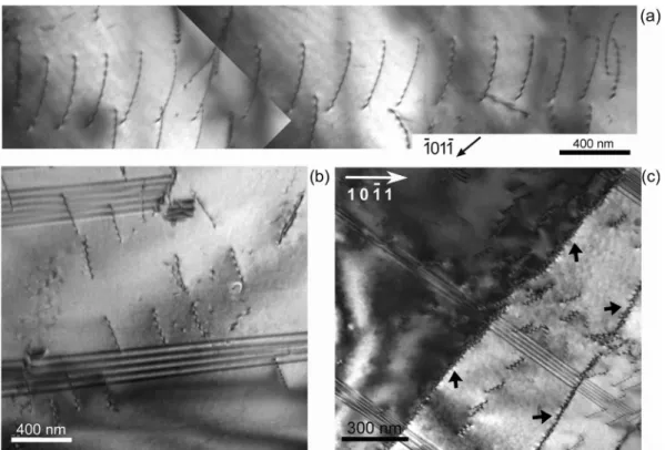
dislocations. Other type of arrangement frequently detected are arrays of dislocations leading to some polygonization of the grain structure (Fig. 4c), and more rarely dislocation dipoles. Dislocations in arrays as inFig. 4c are not regularly spaced with some discontinuities inside the grain.
Dislocation arrays could be observed over quite long distance of several micrometers. An example of such a configuration 10 μm long is presented inFig. 5. The array is lying on basal plane and includes three types of dislocations. The micrograph inFig. 5a shows a part of this array in a quite thin area of the foil. This image shows the presence of two different dislocation systems identified by black and white arrows. The orientation of the grain, with a foil normal lying near a [0111] axis, allows imaging the feature using three different {0111} diffraction vec tors, and makes possible the identification of the three 〈a〉 disloca tions. This is done in a thicker area of the foil along the same array. For each particular {0111} type reflection, one set of 〈a〉 dislocation is out of contrast, as indicated by a black arrow inFig. 5b d. Interaction is evidenced between two different basal 〈a〉 dislocations, the principal pile up is represented by 1/3 [1120] dislocations (white arrows in Fig. 5a), while the 1/3 [2110] dislocations exhibit a more extended distribution (black arrows inFig. 5a). The interaction between these two groups of dislocations creates segments of 1/3 [1210] dislocations (Fig. 5c) leading to a more or less locally regular dislocation network. Other less common glide systems, identified near grain boundaries, are illustrated in Fig. 6. The foil normal of the region examined in Fig. 6a and b is close to the [1120] axis, and the dislocations were again analyzed using the (1101) reflection.Fig. 6a shows two sets of〈a〉 dislocations: one pile up corresponds to dislocations that glide from bottom right to top left of the image (black arrows, letter A), the other one (identified by white arrows, letter B) is lying in another plane. This latter micrograph was taken with a beam direction about 20° away from the [1120] axis.Fig. 6b represents the same area, the foil is inclined 5° from the [1120] axis at almost 90° from the basal plane. The dislocations B inFig. 6b are extremely bent and their projected length is very short, indicating that they actually lie in the basal plane. On the other hand, dislocations from the pile up A are straight and their projected length
Fig. 4. Microstructure features of polycrystalline cobalt strained at 0.8% in the stage A: (a) dislocation pile-up, (b) single dislocations and (c) polygonization (polygonization walls are indicated by black arrows).
consequence of strain hardening (i.e. due to the increasing number of sessile dislocation in the latter stages of deformation), the mean free path of mobile dislocations is reduced, resulting in a continual decrease in the AE activity. Owing to the very low stacking fault energy of cobalt, cross slip of dislocations is difficult and twinning processes most like dominate at higher strains (stage B). In the beginning of the stage B, the strain hardening rate exhibits a transition as it starts to decrease (with increasing stress) much slower compared with the stage A. Such a be havior suggests a change in the deformation mechanism from disloca tion glide to twinning. Moreover, the AE response in the stage B de creases significantly in terms of counts per event, whereas the amplitudes of the signals remain relatively high. This is another clear manifestation of twinning as the AE waveforms corresponding to twinning are known to be burst like short individual AE signals with a relatively high amplitude. A last stage appears just before the fracture, manifested by a wavy character of strain hardening rate in the end of the test. In addition, this stage is accompanied by the occurrence of more random AE events possessing a low number of counts and rela tively high amplitude, which is another signature of a breakdown of the sample.
It should be mentioned that since the deformation as well as the AE activity result from an interplay of different effects (e.g. there is typi cally no well defined point where one deformation mechanism stops and the other arises), we can, in particular, assess only which one dominates.
3.2. Deformation Mechanisms in the Stage A: Gliding Process
Microstructure analysis was performed in samples deformed to 0.8%, using different diffracting vectors, via bright field mode in two beam conditions. The Burgers vectors of the dislocations were char acterized using the standard contrast extinction rules. Transmission electron microscopy observations indicate that dislocation glide is the principal deformation mechanism activated in Stage A. Planar dis location structures, i.e. pile ups and single dislocations, were observed (Fig. 4a, b). Mobile dislocations were identified as ⟨a⟩ type
on the image increased when compared toFig. 6a, confirming that they are not lying in the basal plane, but rather in a prismatic plane.Fig. 6c and d show a smaller pile up located near a grain boundary, the foil normal in this sample is close to the [1213] axis. Both images were taken under {0111} type reflection, while foil is inclined at about 47° from the basal plane. InFig. 6c, dislocations are clearly distinguished in the left part of the image, while inFig. 6d the dislocations are edge on. A ste reographic analysis indicates that those dislocations may lie in the (1101)pyramidal plane. Such glide systems have not been so far re ported for polycrystalline cobalt. We conjecture that they are observed close to GB due to special stress state in such locations.
3.3. Deformation Mechanisms in the Stage B: Characterization of Twin Systems
The results concerning the microstructure of samples deformed to 4.1%, which is within the hardening stage B, reveal the presence of twins in the vast majority of grains observed as well as corresponding high density of dislocations. Twins exhibit variable size, ranging from hundreds of nanometres to a few micrometers (Fig. 7a). Some twins are very long and feature extremelyflat interfaces. Others show lenticular shape and are comparatively smaller. Several twin variants are fre quently present in a single grain. Stacking faults are also sometimes depicted inside the twin as revealed by the diffraction patterns streaks.
Fig. 5. Interaction between different basal 〈a〉 dislocations in polycrystalline cobalt strained at 0.8% in the stage A: (a) image of two sets of dislocations in a very thin region of the foil; (b), (c) and (d) represent another region of the pile-up showing the interaction be-tween the two sets of dislocation system.
Fig. 6. Others slip systems in the stage A. Both regions where studied under the same type re-flection, g = 0111. In (a) and (b) images where taken under the same diffraction vector but are inclined differently about [1120] axis. In (c) and (d) images where taken using different types of g = 0111 reflection.
Fig. 7. General microstructure of polycrystalline cobalt deformed in the Stage B showing: (a) twins of different sizes (b) slip bands.
The matrix is highly deformed and presents a high density of slip bands, while twins seem to be superimposed onto such dislocation arrays (Fig. 7b). Plasticity in the stage B is mainly controlled by twinning and further discussion will focus principally on this deformation me chanism.
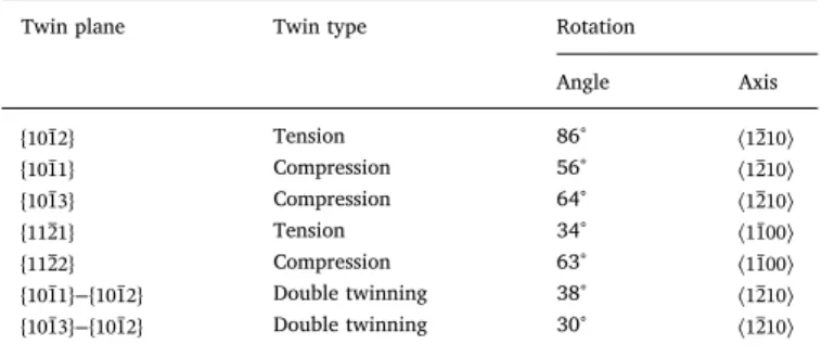
Twin systems in hcp metals have been reviewed, and it was shown that different twin types may operate depending on loading conditions and c/a ratio[2]. Those systems are typically labelled by the twinning plane. Depending on the c/a ratio, a given twin system may induce either a contraction or dilatation along thec axis, which is called ten sion or compression twins, respectively[21]. Identification of the dif ferent modes of twinning can be made by measuring the rotation angle with respect to the appropriate zone axis or by identifying the overlap of very precise axis as proposed by Partridge [2]. As can be seen in Table 1, most of those twins can be identified by a given rotation of diffraction pattern about 〈1210〉 zone axis. Twin classification was based on a maximum deviation of ± 5° from the precisely know mis orientation angle given in Table 1. In order to measure the relative importance of each type of twinning we evaluated their occurrence. The analysis was made in around 50 grains, allowing the classification of hundreds of twins.
Fig. 8 shows the appearance of the most common twin type in polycrystalline cobalt in the present conditions, with an occurrence frequency of around 66%. The typical selected diffraction pattern used for the identification is also present. The twin and the matrix are related by an 86° rotation around the 〈1210〉axis (Fig. 8c) so that this can be classified as {1012} twin. When this type of identification was not pos sible, because of the unfavourable orientation of the grain, the overlap of the [0001]Tand[1100]Maxes in the matrix and the twin was used to ensure the identification (Fig. 8d). The analysis of different grains in dicates that the morphology and size of this type of twin is highly variable.Fig. 8a shows a grain containing a twin of the same type and variant. Such twins are rather wide (1 3μm), but {1012} twin can be relatively thin (0.1μm) and of lenticular shape as depicted inFig. 7b. Fig. 9shows the morphology of other types of twins, which were always present when analysing the sample in TEM, but to a lesser extent when compared to the {1012} type. The second most frequent twin in cobalt is the {1011} twin, identified by a rotation of 56° about the 〈1210〉
axis (Fig. 10a). The morphology of this twin is always the same, they are small (< 1μm) and narrow, with interfaces almost parallel to each other. Another single twin observed in cobalt is the {1013} twin, which is also very thin and narrow like the {1011} twin. In this case, the twin and the matrix are related by a 64° rotation around the 〈1210〉axis (Fig. 10b). Stacking faults are evidenced in both, the twins and the matrix, but in the former case the density is much more important as revealed by the existence of streaks in the diffraction pattern corre sponding to the twin.
The last single twin that could be identified in the polycrystalline cobalt was the {1121} one (Fig. 9b), having a thickness of around 400 nm. Its interfaces are extremelyflat, and it is very long (around 10μm), sometimes occupying the whole grain. This twin is rotated 34° around the 〈1100 axis (〉 Fig. 10c) and is the only twin type encountered with such rotation axis.
The presence of double twinning was also evidenced in the stage B and is depicted in diffraction patterns inFig. 11. For the sake of clarity, diffraction patterns were not indexed. Double twinning occurs in polycrystalline cobalt once a compressive twin is already formed. Basal planefirst rotates by 56° around 〈1210 axis to form {1011} twin, then〉 rotates again around the same axis by 86° to form the second order {1012} twin, resulting in the misorientation angle between the matrix and the secondary twin of 38°, as depicted inFig. 11a. Double twinning mode{1013} {1012} was also identi− fied in the samples deformed in the stage B, with the corresponding diffraction pattern presented in Fig. 10b. Basal plane rotates 65° around the 〈1210 axis, and then 86°〉 around the same axis, again. Finally, the misorientation angle between the matrix and the secondary twin is 30°. These twins are thin and small and the interface between primary and secondary twins was not always easy to reveal.
4. Discussion
The present work gives a general overview of the deformation of pure cobalt using transmission electron microscopy. The discussion focuses on the new results concerning the mechanisms of plasticity in polycrystalline cobalt in each stage of work hardening, supported by a statistical analysis of the twin formation.
Deformation in the stage A is governed by the glide of dislocations, most of them with ⟨a⟩ Burgers vector. The predominant dislocation configuration correspond to ⟨a⟩ dislocations pile ups in the basal plane, some arrays of dislocations leading to polygonization of the grains are observed, as well. Dislocation dipoles are also present but to a lesser extent. Hence their influence on the deformation of polycrystalline cobalt is certainly limited. Other glide systems were also partly iden tified: ⟨a⟩ type dislocations not lying in the basal plane that are mainly located near the grain boundaries. The relative occurrence of prismatic and pyramidal (P1) system could not be quantified.
Deformation twins are the dominant deformation mechanism in the stage B. They are traditionally categorized as being either tension or contraction twins. For hcp cobalt with the c/a ratio below√3, an ex tension twin such as {1012} type usually forms when a tension strain is applied along the c axis, while a contraction twin such as {1011} often appears when a compression strain is applied along the c axis [2].
Twin plane Twin type Rotation
Angle Axis {1012} Tension 86° 〈1210〉 {1011} Compression 56° 〈1210〉 {1013} Compression 64° 〈1210〉 {1121} Tension 34° 〈1100〉 {1122} Compression 63° 〈1100〉 − {1011} {1012} Double twinning 38° 〈1210〉 − {1013} {1012} Double twinning 30° 〈1210〉
Fig. 8. (a, b) TEM microstructure re-presenting different size and morphologies of {1012} twin in cobalt; (b, d) typical dif-fraction patterns used for identification. Diffraction pattern of the matrix is re-presented by continuous line, and for the twin by dotted line.
Table 1
Rotation axis and angles used for identification of twinning and double twinning modes in cobalt.
During the deformation of polycrystalline cobalt, several modes of twinning including compression ({1011} and {1013}), tension ({1012}and{1121})), as well as double twinning were identified inside the same grain. In a great majority of examined grains, the predominant type is the {1012} mode, which is the most common mode in hcp metals, and it can be present together with other twin modes.
In order to make a statistical evaluation, 45 grains were analyzed, allowing for the identification of a hundred of twins. The occurrence frequency was estimated for each type of twin as the ration of the number of a given twin type over the total number of twins observed. The results indicate that tension twins of the {1012} mode are pre dominant (66%). The second most frequently occurring twin mode is
A high density of planar faults is detected in {1011}, {1013}, and {1012} twins, as evidenced by streaks in different electron diffraction patterns
Fig. 9. TEM image of the morphology of: (a) {1011} and (b) {1121} twins.
Fig. 10. Typical diffraction patters of: (a) {1011} twin, (b) {1013} twin and (c) {1121} twin. Diffraction pattern of the matrix is represented by continous line, and for the twin by dotted line.
Fig. 11. Typical diffraction patterns of double twinning in polycrystalline cobalt deformed at 4.1%. A schematic representation of lattice orientation relation is also present: (a) −
{1011} {1021}twin and (b){1013}−{1021}twin. Matrix is represented by solids lines,first rotation by green line, second rotation by red ones. (For interpretation of the references to color in thisfigure legend, the reader is referred to the web version of this article.)
Table 2
Relative fractions (f) of twin number or twin boundary length for three distinct mechanical loadings (atension,bdynamic plastic deformation,ccompression).
Twin type {1012} {1121} {1122} {1011} {1013} {1011} {1012}│ {1013} {1012}│
f of twin number (%) Ta(this study) 66 4 – 16 6 5 3
f of twin boundary length (%) DPDb[21] 73.1 10.4 0.8 2.3 11.6 0.7 1.1
Cc[21] 82.1 3.8 0.8 1.2 9.2 1.8 1.1
{1011} type (16%). Different single or double twins are present in similar proportions in the range of (3 6)% (Table 2). After an extensive litera ture search, the only complete analysis of deformation twins in cobalt was published in recent paper [21]. In this work a statistical study was made using a scanning electron microscope coupled with an electron backscattering diffraction system (SEM EBSD), which allowed for a more rigorous study of the samples. When comparing these results with the present observations they were found to be roughly similar. Zhang et al. [21] reported that fraction of tension twins is very high, in particular it is the {1012} mode which reaches 73.1% in the samples obtained by dy namic plastic deformation, and 82.1% in the samples deformed by compression test. Our results complement those of Zhang et al. with a third mode of deformation (monotonous tensile experiments).
The difference in the frequency of occurrence of different twin modes, as seen in Table 2, can be partially explained when we consider the differences in the calculation methods. In the present, study the number of twins in considered rather than the length of twin bound aries. In the analysis of Zhang et al. [21] the length of each twin boundary was automatically measured and compared with the others. In the present work, {1012} and {1121} twins are larger than the other twin modes. If calculation of the ratio is based on the length, the fre quency of occurrence will naturally increase. In the same way, the frequency of smaller twins (compression and double twins) will be re duced. In these cases, results will match better the calculations of Zhang et al. Finally, the {1122} mode was not detected in the present study, most likely because of the very low amount of such twins.
\\One has also to keep in mind that Zhang et al. performed com pressive loading tests. According to the texture orientation of their spe cimens, loading direction was in their case perpendicular to the c di rection of the crystal structure, in agreement with the finding that tension type (related to the c direction) twins are mainly activated. By contrast, in the present study, tensile testing was performed, with a load axis oriented between 50° and 60° off the c direction, according to the measured texture reported in Fig. 1. Despite the different geometry of mechanical loading with respect to crystal orientation, it appears that the relative occurrence of twin types obtained in this study is very similar to Zhang et al. [21] results. This finding suggests that the grain orientation with respect to the applied load has only a limited effect in Co. This fact is supported by the observation of both compression and tension type twins in the same grain, as reported in the present study and in [21]. Similar situation was also reported in other hcp metals [32,33].
5. Conclusion
The mechanisms of plastic deformation in hcp cobalt were revealed in this study using transmission electron microscopy (TEM) and acoustic emission measurements. Plastic deformation was found to be driven by dislocation glide in thefirst stage (A), whereas deformation twinning was the dominant mechanism in the latter stage (B). Microstructures in the two stages of work hardening have been characterized in detail using trans mission electron microscopy, by means of interrupted uniaxial tensile tests. Observed microstructures (i.e. dislocation slip systems and twinning systems) led to the following conclusions:
Plasticity during stage A of work hardening is driven by planar and single glide of basal⟨a⟩ dislocations.
Twinning nucleation and growth are the most active deformation mechanisms during the stage B of work hardening. Compression, tension, as well as double twins are frequently observed within the same grain.
Several twinning modes, including {1012}, {1011},
− −
{1013}, {1121}, {1011} {1012}, and {1013} {1012}, take place during deformation in the stage B of work hardening.
A statistical analysis shows that {1012} twins are the most common twins in hcp polycrystalline cobalt.
References
[1]B. Legrand, Relation entre la structure electronique et la facilité de glissement dans les métaux hexagonaux compacts, Philos. Mag. B 49 (1984) 171–184.
[2] P.G. Partridge, The crystallography and deformation modes of hexagonal close-packed metals, Metall. Rev. 12 (1967) 169–194.
[3] F. Long, M.R. Daymond, Z. Yao, Deformation mechanism study of a hot rolled Zr-2.5 Nb alloy by transmission electron microscopy. I. Dislocation microstructures in as-received state and at different plastic strains, J. Appl. Phys. 117 (2015) 094307 1–094307 10. [4] A. Couret, D. Caillard, An in situ study of prismatic glide in magnesium-I. The rate
controlling mechanism, Acta Metall. 33 (1985) 1447–1454.
[5] J. Koike, Enhanced deformation mechanisms by anisotropic plasticity in polycrystalline Mg alloys at room temperature, Metall. Mater. Trans. A 36 (2005) 1689–1696. [6] K. Máthis, K. Nyilas, A. Axt, I. Dragomir-Cernatescu, T. Ungár, P. Lukáč, The evolution of
non-basal dislocations as a function of deformation temperature in pure magnesium de-termined by X-ray diffraction, Acta Mater. 52 (2004) 2889–2894.
[7] D. Ando, J. Koike, Y. Sutou, Relationship between deformation twinning and surface step formation in AZ31 magnesium alloys, Acta Mater. 58 (2010) 4316–4324.
[8] X. Shi, A.A. Luo, S.C. Sutton, L. Zeng, S. Wang, X. Zeng, D. Li, W. Ding, Twinning behavior and lattice rotation in a Mg–Gd–Y–Zr alloy under ballistic impact, J. Alloys Compd. 650 (2015) 622–632.
[9] H. Yoshinaga, T. Obara, S. Morozumi, Twinning deformation in magnesium compressed along the C-axis, Mater. Sci. Eng. 12 (1973) 255–264.
[10] N. Bozzolo, L. Chan, A.D. Rollett, Misorientations induced by deformation twinning in titanium, J. Appl. Crystallogr. 43 (2010) 596–602.
[11] R.J. McCabe, G. Proust, E.K. Cerreta, A. Misra, Quantitative analysis of deformation twinning in zirconium, Int. J. Plast. 25 (2009) 454–472.
[12] W. Betteridge, The properties of metallic cobalt, Prog. Mater. Sci. 24 (1980) 51–142. [13] C. Hitzenberg, H.P. Karnthaler, A. Korner, Electron microscopy of H.C.P. cobalt at various
temperatures, Acta Metall. 33 (1985) 1293–1305.
[14] A. Seeger, H. Kronmüller, O. Boser, M. Rapp, Plastische Verformung von Kobalteinkristallen, Phys. Status Solidi B 3 (1963) 1107–1125.
[15] R.T. Holt, High Temperature Deformation of Cobalt Single Crystals, PhD Thesis The University of British Columbia, 1968.
[16] H.M. Thieringer, Zur Plastizitat hexagonaler Kolbalteinkristalle, Z. Met. 59 (1968) 476–491.
[17] A. Korner, H.P. Karnthaler, Weak-beam study of glide dislocations in h.c.p. cobalt, Philos. Mag. 48 (1983) 469–477.
[18] J. Dille, J. Charlier, R. Winand, The structure and mechanical properties of thick cobalt electrodeposits, J. Mater. Sci. 32 (1997) 2637–2646.
[19] A.H. Barry, G. Dirras, F. Schoenstein, F. Tétard, N. Jouini, Microstructure and mechanical properties of bulk highly faulted fcc/hcp nanostructured cobalt microstructures, Mater. Charact. 91 (2014) 26–33.
[20] V.M. Marx, C. Kirchlechner, B. Breitbach, M.J. Cordill, D.M. Többens, T. Waitz, G. Dehm, Strain-induced phase transformation of a thin Cofilm on flexible substrates, Acta Mater. 121 (2016) 227–233.
[21] X.Y. Zhang, Y.T. Zhu, Q. Liu, Deformation twinning in polycrystalline Co during room temperature dynamic plastic deformation, Scr. Mater. 63 (2010) 387–390.
[22] X.Y. Zhang, B. Li, X.L. Wu, Y.T. Zhu, Q. Ma, Q. Liu, P.T. Wang, M.F. Horstemeyer, Twin boundaries showing very large deviations from the twinning plane, Scr. Mater. 67 (2012) 862–865.
[23] Y.T. Zhu, X.Y. Zhang, Q. Liu, Observation of twins in polycrystalline cobalt containing face-center-cubic and hexagonal-close-packed phases, Mater. Sci. Eng. A 528 (2011) 8145–8149.
[24] Q. Sun, X.Y. Zhang, R.S. Yin, Y. Ren, L. Tan, Structural characterization of {1013} twin boundaries in deformed cobalt, Scr. Mater. 108 (2015) 109–112.
[25] Q. Sun, X.Y. Zhang, Y.C. Wang, Y. Ren, L. Tan, Q. Liu, Structural characterization of twin boundaries in deformed cobalt, Mater. Charact. 116 (2016) 44–47.
[26] C.C. Sanderson, Deformation of Polycrystalline Cobalt, PhD Thesis The University of British Columbia, 1972.
[27] D. Drozdenko, J. Bohlen, F. Chmelík, P. Lukáč, P. Dobroň, Acoustic emission study on the activity of slip and twin mechanisms during compression testing of magnesium single crystals, Mater. Sci. Eng. A 650 (2016) 20–27.
[28] A. Vinogradov, A. Danuyk, E. Pomponi, Mechanisms of Plastic Deformation and Acoustic Emission in ZK60 Mg Alloy, Proc. 30th Eur. Conf. Acoust. Emiss. Test. 2012. [29] C. Hitzenberg, H.P. Karnthaler, A. Korner, Contrast analysis of intrinsic and extrinsic
stacking faults in H.C.P. cobalt, Phys. Status Solidi A 89 (1985) 133–145.
[30] G. Fleurier, E. Hug, M. Martinez, P.-A. Dubos, C. Keller, Size effects and Hall–Petch re-lation in polycrystalline cobalt, Philos. Mag. Lett. 95 (2015) 122–130.
[31] C.R. Heiple, S.H. Carpenter, Acoustic emission produced by deformation of metals and alloys—a review, part I and II, J. Acoust. Emiss. 6 (1987) 177–204.
[32] I.J. Beyerlein, L. Capolungo, P.E. Marshall, R.J. McCabe, C.N. Tomé, Statistical analyses of deformation twinning in magnesium, Philos. Mag. 90 (2010) 2161–2190.
[33] C. Lou, X. Zhang, Y. Ren, Non-Schmid-based {10 12} twinning behavior in poly-crystalline magnesium alloy, Mater. Charact. 107 (2015) 249–254.
[34] S.G. Song, G.T. Gray, Structural interpretation of the nucleation and growth of de-formation twins in Zr and Ti—II. Tem study of twin morphology and defect reactions during twinning, Acta Metall. Mater. 43 (1995) 2339–2350.
[35] X.Y. Zhang, B. Li, Q. Liu, Non-equilibrium basal stacking faults in hexagonal close-packed metals, Acta Mater. 90 (2015) 140–150.
[36] J. Tu, X.Y. Zhang, Z.M. Zhou, C. Huang, Structural characterization of {1012} twin tip in deformed magnesium alloy, Mater. Charact. 110 (2015) 39–43.
[37] A. Ostapovets, P. Molnár, On the relationship between the“shuffling-dominated” and “shear-dominated” mechanisms for twinning in magnesium, Scr. Mater. 69 (2013) 287–290.
[38] M. Gong, J.P. Hirth, Y. Liu, Y. Shen, J. Wang, Interface structures and twinning me-chanisms of twins in hexagonal metals, Mater. Res. Lett. (2017) 1–16,http://dx.doi.org/ 10.1080/21663831.2017.1336496.
[39] I.J. Beyerlein, J. Wang, M.R. Barnett, C.N. Tome, Double twinning mechanisms in mag-nesium alloys via dissociation of lattice dislocations, Proc. R. Soc. Math. Phys. Eng. Sci. 468 (2012) 1496–1520.
[40] M.R. Barnett, Z. Keshavarz, A.G. Beer, X. Ma, Non-Schmid behaviour during secondary twinning in a polycrystalline magnesium alloy, Acta Mater. 56 (2008) 5–15. [41] É. Martin, L. Capolungo, L. Jiang, J.J. Jonas, Variant selection during secondary twinning
in Mg–3%Al, Acta Mater. 58 (2010) 3970–3983.
used for twin identification. According to Song and Gray [34], who studied deformation twinning in Ti and Zr, this kind of stacking faults is formed by a misplacement of atoms in the shearing transformation during twinning. The configuration and structure of the observed stacking faults are different from intrinsic stacking faults, that are formed by dislocation dissociation or vacancy collapse. Zhang et al. [25,35] also reported the presence of high density of stacking faults within {1012} and {1011} twins in cobalt, and related this feature to the migration of in coherent twin boundaries. Besides, atomistic simulation performed to understand the formation of this kind of stacking faults indicates that when the twin boundary is coherent or nearly coherent, no stacking faults are generated [35]. Habit planes of twins analyzed in the present work are rather incoherent as explained in the following paragraph.
Wherever possible, the habit planes of {1012} twin were determined. Twin boundaries are rarely aligned along the theoretical crystal lographic plane. The deviation from the habit plane in cobalt and also magnesium [22,24,25,36] can be explained by the predominant atomic shuffling, which plays a prevailing role in the {1012} mode in compar ison with the shear processes. However, there is no consensus regarding these deviations. Ostapovets and Molnar [37] reported that these de viations can be caused by a deformation inhomogeneity produced by defects such as twinning dislocations (TDs) on the microscopic level. Gong et al. [38] analyzed different types and configurations of inter faces, concluding that for {1012} twins only one type of TD is present and the interface has accommodated large stresses, causing the twin to have a lenticular shape. Twinning boundaries for compression {1011} and {1013} modes are also incoherent. Sun et al. [24,25] found that twin boundaries are not straight and that the interfacial structures are composed of different types of facets.
Finally, the present observations also revealed the formation of two double twinning modes {1011} − {1012} and {1013} − {1012}. They are of lenticular shape and small in size. The frequency of their occurrence is low and very similar whatever the mode. Double twinning has been al ready observed in Mg alloys using various electron microscopy methods [7,39 41] and in Co by using the EBSD analysis [21]. According to the analysis of Mg alloys, second generation twins do not follow the Schmid's law and are associated with the onset of the fracture.
![Fig. 1. EBSD analysis of polycrystalline cobalt: (a) distribution of hcp and fcc phases and (b) corresponding pole figure showing the basal {0001} texture of the hcp phase.mainly related to nanocrystalline samples [19], thin films [20], and](https://thumb-eu.123doks.com/thumbv2/123doknet/3094210.87637/3.892.154.747.807.1091/analysis-polycrystalline-distribution-corresponding-figure-showing-texture-nanocrystalline.webp)