This is an author-deposited version published in: https://sam.ensam.eu Handle ID: .http://hdl.handle.net/10985/20058
To cite this version :
Mohamad EL YOUSSEF, Stephane CLENET, Adrien VANGORP, Abdelkader BENABOU, Pierre FAVEROLLE, Jean-Claude MIPO - Improving global ferromagnetic characteristics of laminations by heterogeneous deformation - IEEE Transactions on Energy Conversion p.1-9 - 2021
Any correspondence concerning this service should be sent to the repository Administrator : [email protected]
Abstract— During electrical machine manufacturing, the
process may induce plastic mechanical strains, especially in the magnetic core. However, magnetic properties are highly sensitive to the material mechanical state. Thus, the performances of electrical machines, which also rely on the magnetic material properties, are often deteriorated. This paper proposes an approach to reduce the impact of the forming process on the magnetic core performances by creating high localized heterogeneous deformations instead of having a low homogeneous deformation distributed on the whole structure. A NO (non-oriented) FeSi (1.3%) electrical steel (M330-35A) is characterized after uniaxial tensile test. Samples are deformed either in heterogeneous or in homogeneous ways while keeping the same global deformation. Experimental measurements show that, for the same displacement value, the heterogeneous configuration, with localized strain, deteriorates less the global magnetic properties than the homogeneous configuration. These results are supported by a magneto-mechanical modeling approach that predicts accurately the physical behavior of the test samples.
Index Terms— Electrical Machine, Magnetic characterization,
Manufacturing process, Non-oriented FeSi steel, Plastic strain
I. INTRODUCTION
he manufacturing process of electrical machines involves different stages (cutting, pressing, forming, welding annealing…etc.) that lead in general to the degradation of magnetic properties of electrical steel laminations [1,2]. For example, in [3,4] the impact of several manufacturing processes on the magnetic properties of NO electrical steel sheet is investigated, it shows a magnetic behavior degradation as well as significant iron loss increase. Some studies are focused on quantifying the impact of manufacturing process on magnetic properties like the cutting techniques [5–8]. In [9] for example, the authors show that the iron loss can be reduced by about 5.8% when minimizing the cutting clearance of a punching process. In [10–12] it was found that hysteresis losses increase with the square root of the strain. On the other hand, the eddy current losses decrease. In [13], the effect of the compaction on the magnetic properties has been investigated showing the degradation of magnetic behavior
Mohamad El Youssef and Adrien Van Gorp are with Arts & Metiers Institute of Technology; Mechanics, Surfaces and Materials Processing (MSMP); 8 Boulevard Louis XIV 59046 Lille, France.
Stephane Clenet and Abdelkader Benabou are with Univ. Lille, Centrale Lille, Arts et Metiers ParisTech, HEI, HeSam, EA 2697 L2EP – Laboratoire d’Electrotechnique et d’Electronique de Puissance, F-59000 Lille, France
Jean-Claude Mipo and Pierre Faverolle are with Valeo-2 Rue Andre Charles Boulle, 94000 Creteil, France
due to the material properties modification. A description of different forming processes, like the rolling stage during the slinky stator manufacturing, for different applications as well as their consequences on the distribution of the plastic strain in each case could be find [14]. Thus, researchers focused on the relationship between mechanical or microstructural properties and the magnetic behavior [15–17]. Results show that the plastic strains and residual stresses are detrimental to magnetic properties.
In order to reduce the impact of the manufacturing process, three approaches are proposed in the literature. The first approach consists in determining the influence of each step of the process [18] and find the optimal process parameters that could result in less degradation of the magnetic material behavior. The second approach focuses on magnetic properties recovery via heat treatment application after manufacturing. Results show that the magnetic behavior could be recovered partially while this additional step leads to an additional cost and an increase of the total losses at high frequencies [19,20]. The third approach consists in design optimization [21]. This latter is increasingly sustained by considering multi-physical phenomena [22] and the impact of the manufacturing process [23]. However, there is still no alternative proposed in the literature to alleviate the impact of manufacturing process by considering, as a whole, the couple geometry/process and by acting on both in order to improve the performances.
As mentioned before, the forming process leads to a high degradation of the magnetic behavior of the steel sheet. In particular, the deformation of a slinky stator core is almost homogeneously distributed. This is due to the constant force experienced by the lamination during the rolling process. This homogeneous deformation is not mandatory and solution with heterogeneous deformation can be imagined. The aim of this heterogeneous deformation is to localize highly the deformation required to roll the lamination sheet and to keep safe the remaining parts of the lamination without damaging its properties by the deformation. Since the degradation rate of the magnetic properties decreases with the deformation, it can be expected that the global behavior remains better than with a homogeneous deformation, even if the magnetic behavior is worse in some regions. To go further on the concept of heterogeneous deformation, one should investigate, first on a simple geometry, the effect of heterogeneous deformation and develop a model in order to predict the effect of localized deformations. The heterogeneous deformation approach could offer possibilities to develop new forming processes for electrical machine manufacturing.
Improving global ferromagnetic characteristics
of laminations by heterogeneous deformation
Mohamad El Youssef, Stéphane Clenet, Adrien Van Gorp, Abdelkader Benabou,
Pierre Faverolle,
Jean-Claude Mipo.
deformations on samples with a simple geometry have been compared. In addition, a magneto-mechanical model which predicts the global magnetic behavior of a sample with a heterogeneous deformation is presented. First, the context and the experimental approach are detailed. Then, a comparison of the performances, of samples deformed heterogeneously and homogeneously, is carried out experimentally. Finally, a model based on the coupling of finite element mechanical and magnetic models will be described and the results of the simulation are compared with the experimental ones in order to validate the proposed approach.
II. CONTEXT
The forming process represents a specific manufacturing step; it consists in applying suitable stresses, which yield to plastic deformation of the materials in order to get the desired shapes, according to the product geometry and its mechanical functionality. Considering the conventional slinky stator forming process, which consists in rolling a single band of lamination, already punched to make the slots, around an axis perpendicular to its plane to obtain the stator core geometry (see Fig.1a). It has been shown that the iron losses in the stator have been doubled compared to the iron losses of the raw material due to the plastic deformation induced by the rolling and the cutting processes [18]. As presented in Fig.1a, the plastic strain distribution in the stator yoke could be considered approximately uniform with low intensity. This specific process could be modified in order to get a heterogeneous (alternated) distribution of plastic strain intensity. This will result in a new stator geometry (Fig.1b) which is close to the original one (Fig.1a). However, in the heterogeneous configuration the plastic strain is localized but with a higher level than the homogeneous plastic strain distribution met with the conventional slinky stator.
The difference between the conventional slinky and the polygonal slinky solution is the plastic strain distribution which is almost homogeneous in the first case and drastically localized but with a high level in the second case. The global magnetic behavior of both solutions will be different and should be compared particularly to see if the polygonal slinky is competitive.
However, comparing these two solutions experimentally is not straightforward because it requires setting up the process of fabrication of the polygonal slinky stator which does not exist. Moreover, in order to be sure that the polygonal slinky stator is a competitive solution, the design should be optimized. In fact, the polygonal shape will be accompanied with important modifications and consequences on electrical machines performances such as the winding process.
In the present paper, we propose to evaluate the impact of heterogeneous plastic strain distribution on the magnetic characteristics of samples adapted for conventional laboratory equipment. In order to show that the control of the stress and plastic strain distribution can reduce the degradation of the global magnetic core performances, samples of rectangular shapes are considered. They will be subjected to either
magnetic performances will be compared (see Fig.2).
The experimental approach is presented in the following. It explains how the local deformation is generated and controlled for the considered samples. Then, the global magnetic characteristics of both types of samples, which represent homogeneous and localized plastic strain, are compared experimentally.
III. EXPERIMENTAL METHOD
A. Experimental apparatus
Two characterization devices have been used in this work. The first one is a 100 kN INSTRON tensile testing machine equipped with a clip-on extensometer which is used to measure the deformation accurately with an error less than 0.1% FRO (Full Range Output).
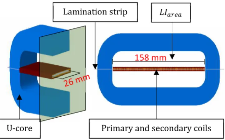
The second equipment is a MPG200D Brockhaus SST (single sheet tester). It is used to carry out the magnetic measurements on a single lamination sheet. It consists of a double yoke measuring coil system and a contra-inductivity to compensate air flux according to the standard IEC 60404-3. The magnetic path length between the legs of yokes which represents the LIarea (length of the area of interest) for
magnetic characterization is equal to 158mm (Fig.3). The system meets the IEC, ASTM and GB standards with an adjustment of nominal values better than 0.2%.
Fig.1: Conventional slinky stator, representing a quite uniform deformation of its yoke, versus the polygonal slinky stator with localized deformation.
Fig.2: Same global deformation carried out with two configurations (overall the sample vs local deformation).
B. Samples and preparation
In order to show the benefit of heterogeneous deformation, the experimental approach presented in Fig.4 has been followed. Four non-oriented M330-35A grade lamination sheets are considered with a rectangular shape of 300 mm x 50 mm.
b)
Conventional Slinky
Polygon Slinky
a)
Low strain level High strain levelSame global deformation
High strain level Low strain level
Homogenous
Heterogeneous
Fig.3: Single sheet tester measuring coils design.
In Table 1, we can find the chemical composition and also the magnetic properties provided by the supplier. The first sample referred by Sraw represents our reference sample which
is not submitted to any mechanical state modification that could change its properties. The three remaining samples are cut in order to be able to impose the desired deformation (Fig.4a). The second sample referred by Shom represents the
sample that includes homogeneous deformation along LIarea.
The Shtr1 and Shtr2 refer to the samples that include a
heterogeneous deformation on a length of 50 mm and 25 mm respectively (Fig.1a).
Table 1: Chemical composition (a) and magnetic properties (b) provided by the supplier for the M330-35A electrical steel.
a) Chemical composition C Mn P 18 PPM 2849 PPM -Si Al S 13073 PPM - 35 PPM b) Magnetic properties 1,5T 2,65 W/kg 3,3 W/kg max B2500 1,613T 1,61T mini B5000 1,702T 1,7T mini B10000 1,823T 1,82T min
The deformation is controlled by Ls which represents the
length of the Sarea (slots area). This area is the region where the
deformation will occur in the sample. In fact, since the Sarea
width is smaller than the initial width of the sample, the deformation will be localized within the Sarea during the tensile
force application. Considering the whole sample, we obtain then a configuration with a heterogeneous deformation. The smaller Sarea (or Ls), the higher the localized deformation is.
Also, in order to reduce parasitic effect of the cutting, the samples were cut by water jet, which represent the less invasive technique compared with laser and punching [25] [26].
Before the sample deformation stage, the Shom, Shtr1 and Shtr2
were glued together at their extremities (Garea in Fig.4b). This
enables to have the same global deformation for the three samples. In the present case, a tensile displacement of 0.45 mm is applied, leading to 0.29 mm of plastic deformation after elastic return. Thus, three samples with the same global plastic deformation have been obtained. However, the deformations within the samples are extended over an area Sarea with a
length Ls different from one sample to another (Fig.4c):
-Shom with Ls=158 mm
-Shtr1 with Ls=50 mm
-Shtr2 with Ls=25 mm.
Considering the deformation well localized in the Sarea, it is
expected to have a plastic strain magnitude in the Sarea of about
0.18% for Shom, 0.6% for Shtr1 and 1.2% for SShtr2. Obviously, it
is not possible to have a uniform plastic strain distribution in the Sarea due to the existence of notches that leads locally to
possible stress concentrations and a transition zone will appear. However, it will be shown by numerical simulation, in the next section, that the strain distribution is quite smooth confirming the assumption of localized deformation. Finally, for the magnetic characterization, the four samples have been re-cut in order to have the same dimensions (Fig.4c).
Magnetic measurements have been carried out under a sinusoidal alternating magnetic flux density at a frequency of 50 Hz. The length of the samples (300 mm) is enough to be fully clamped between the legs of the yokes and to have the deformed areas placed in the middle of the LIarea (Fig.4d). The
magnetomechanical behavior of a given magnetic material being quite repeatable [18], we have considered only one sample for each type of deformation Shom, Shtr1 and Shtr2.
C. Comparison of the magnetic characteristics
Using the SST device (see III.a), the B(H) curve is obteined from the measurement of the magnetic flux flowing through the sample and the magnetomotive force applied at its extremities. In the case of the sample Shom, the deformation is
homogeneous in LIarea so the local and global B(H) curves are
supposed to be the same by principle of the measurement method. In the case of the samples Shtr1 and Shtr2, since the
deformation is not homogeneous, the local B(H) curve depends on the location in the sample and especially if the point is located in the area Sarea or outside (Fig.4b). In that
case, the B(H) curve is not the same from one point to another. The measurement with the SST does not give the intrinsic B(H) curve representing the local behavior but an apparent B(H) curve representing the lamination global behavior (a homogenized behavior). We denote in the following Bglo(H) this curve which represents the purpose of the study. In the following, the Bglo(H) curves of the samples will be compared, in order to show that controlling the local deformation can improve the global magnetic properties. In Fig.5, the evolution of the normal Bglo(H) curves measured for the four samples is represented. It can be noticed that Shom has the most
deteriorated behavior meaning that for a given magnetic field H the corresponding value of the magnetic flux density Bglo is the lowest. In addition, it is well pointed out that the magnetic behavior of the sample Shtr1 is more deteriorated than theShtr2
one. Lamination strip
Primary and secondary coils U-core
Fig.4: Schematic synthesis of the experimental approach.
the relative difference ∆H(Bglo)/H on the required magnetic field for the samples Shom, Shtr1 and Shtr2:
∆H(Bglo)/H(Bglo)=(H(Bglo)-Href(Bglo))/H(Bglo) (1) Where the reference Href(Bglo) is the curve measured with the sample Sraw. For all the samples, it is shown that the
difference with the reference B(H) curve increases with the flux density until 1.1 T. For example the Shom, which is the
most deteriorated sample, requires a magnetic field almost five times higher than the one of Sraw at 1.1 T, while the Shtr1 needs
a magnetic field about four times higher and the Shtr2 about
three times higher. These results confirm that the concentration of the deformation (limited the area Sarea by
increasing the strain) is profitable for the global magnetic behavior. However, the gap begins to decrease when approaching the saturation (above 1.2T). In fact, the mechanical state is less influential when the electrical steel is saturated, leading then to a decrease of the gap between the magnetic behavior of the different samples.
Fig.5: The evolution of the Bglo(H) curves, for the different samples
representing different plastic strain distribution overall the sample.
Fig.6: The evolution of the relative difference on magnetic field, for the different samples representing different plastic strain distribution.
Fig.7: The evolution of the total losses and their relative difference, for the different samples representing different plastic strain distribution.
The same trend is observed on the total iron losses measured at 50 Hz as illustrated in Fig.7 (continuous lines). The total iron losses of the sample Shom are the highest and
those of sample Shtr2 are lower than those of the sample Shtr1,
showing again that concentrating the deformation would improve the global magnetic behavior. Also, the relative evolution of the losses, taking the iron losses of the sample Sraw as reference, is presented in Fig.7 (dashed lines). The
maximum gap is reached in the average magnetic flux density region [0.8T; 1.1T] and then the relative iron loss differences decrease when increasing B. The relative differences of iron losses in the saturated region reach, for the different samples, an average value of 20%.
Therefore, two interesting points can be pointed out. First, the impact of heterogeneous deformation is less pronounced on global magnetic behavior than homogeneous deformation. Second, the more the deformation is localized, the better the global magnetic behavior is.
IV. MAGNETO-MECHANICAL MODEL
In the previous section, it has been shown that, when comparing the global behavior of samples with homogeneous and heterogeneous deformations, the impact of plastic strain on the magnetic behavior can be reduced by localizing the deformation. A model based on the coupling of mechanical and magnetic Finite Element Models (FEM) will be developed in order to support this experimental observation.
A. Methodology
Both intrinsic magnetic and mechanical behavior laws are identified from standard experimental tests (homogeneous properties). Regarding the magnetic properties, these are identified for several levels of plastic strain. Then, the intrinsic properties, which depend on the magnetic field and mechanical plastic strain, are considered in the simulation of a magneto-mechanical problem for a heterogeneously strained lamination. For this latter, we consider the case of a slotted sample (Fig.8). The aim is to verify if we are able to construct
a numerical model representing the SST experimental setup to retrieve the experimental results obtained in the previous section. A mechanical FEM will simulate the experimental tensile test, performed on a lamination sheet with 50 mm notches. The electromagnetic FEM will simulate the SST measurements. The plastic strain at the meso-scale will create residual stresses and change grain orientation at the microscopic scale. It modifies the normal B(H) curve and the iron losses, resulting in the degradation of these characteristics [24]. Since the mechanical properties exported from forming process models are at the meso-scale level, the combination of all the mechanical properties will be represented by just the plastic strain level. Consequently, to couple these two models, the magneto mechanical behavior law of the ferromagnetic material relating the plastic strain εp with the B(H) curve is
required. These experimental B(H) curves have been obtained by an experimental campaign (see section IV.C.2) combining tensile tests on a material testing machine and magnetic measurements on a SST.
B. Experimental determination of the behavior laws 1) Tensile test
Mechanical properties are determined by a standard tensile test (ISO 6892-1:2009) using the 100 kN INSTRON machine. The rational mechanical characteristic is given in Fig.9. The Young modulus is equal to 174 GPa, the Yield stress is around 246 MPa and the ultimate true stress is equal to 495MPa. The rational curve which represents the evolution of the true stress with the true strain is considered in the mechanical FE model. 2) Magnetic behavior for different plastic strain levels
In order to measure the B(H) curve evolutions in function of the plastic strain, a set of 11 non-oriented M330-35A electrical steel grade samples, with dimensions 300 mm x 50 mm, were cut by water jet. Before magnetic measurements, each sample has been submitted to different plastic strain magnitudes
ε
p ranging from 0 to 7.6%.As there is a length increase of the lamination samples in the applied tensile force direction; it is obvious that the thickness decreases simultaneously with the width. To account for this effect, two correction steps are considered.
First, concerning the width, the samples are re-cut by water jet in order to have the same width for each sample. It is well-known that after cutting a strained sample, the residual stress is partially released which leads to magnetic property modifications. However, the numerical simulation (see IV-C-1) shows that the residual stresses generated in our case are very low (<10Mpa) and localized at the corner of the notches. Thus the impact of residual stress is considered negligible in this study.
Second, the thickness of each sample is measured by a micrometer screw gauge in order to take it into account the section reduction. The magnetic flux density magnitude is obtained by dividing the flux magnitude, flowing through the sample, by an updated section in function of the deformation. Fig.10 presents the normal B(H) curves corresponding to different plastic strains. It can be noticed that for a given magnetic flux density B, the required magnetic field H is
In addition, it is noteworthy that the degradation is more significant for small plastic deformation. To illustrate this, the evolution of the magnetic field, required to reach a magnetic flux density of 0.9 T for different plastic strains (Fig.10) has been plotted in Fig.11. It is noticeable that the fitting curve has an exponential form. The gradient of the magnetic field magnitude in function of the plastic strain drops brutally at low plastic strain level and remains then weak. This behavior explains the origin of what has been observed experimentally in the previous section. These results are in complete agreement with what can be found in the literature [12].
C. Numerical models 1) Mechanical model
The problem consists of a metal sheet represented by a shell instance with the same dimensions as the sample Shtr1
described in Fig.4. The material characteristics are defined from the rational tensile curve obtained in Fig.9. The instance is constrained at an extremity while the other one is submitted to a displacement constraint equal to the value of the new experimental tensile test (0.75 mm) (Fig.12). The mesh has 73465 triangular elements. The output of this model is the plastic strain and stress distributions which will be used to model the global magnetic behavior.
2) Magnetic model
The purpose of the magnetic FE model is to represent the characterization process using a SST in order to determine the global magnetic behavior Bglo(H) of the laminations. After the tensile test, homogeneous distribution of the plastic strain is expected neither in the longitudinal section nor in the transversal section of the sample. Considering the small thickness of the sample (0.35mm), which represents about three grains, it has been assumed that the strain is constant along the thickness. Consequently, the lamination can be represented in 2D.
Experimentally, the magnetomotive force in the yokes closing the magnetic flux path is assumed to be negligible, because of the high permeability of its constitutive ferromagnetic material and its large section. In our 2D FE model, the yoke closing the magnetic flux path is represented by a rectangular frame with a high magnetic permeability material leading to a negligible magnetomotive force drop along this area (Fig.13).
The magnetic model is solved with the FEMM software linked to Matlab through the toolbox octaveFEMM [27] that enables to create the geometry of the studied domain, to construct the mesh and to solve the nonlinear problem. Also, it draws and assigns all the boundary conditions and magnetic properties all over the sample. It should be mentioned that the model does not consider the hysteresis effect. However, it takes into account the magnetic non-linearity. For different magnitudes of the magnetic field H, the aim is to reconstruct the normal Bglo(H) curve characterizing the global behavior of the sample and to compare it with the experimental one presented in section III (see Fig.5). The challenge now is to couple the mechanical and magnetic FE models, as the plastic
In fact, since the plastic strain distribution is not homogeneous and depends on the position in the Iarea, the B(H)
curve varies from one element of the mesh to another and it has to be determined according to the strain level. So, a model which gives the corresponding B(H,εp) curve for any plastic strain εp is required. Therefore, a set of B(H) curves for 11
magnitudes of deformation have been measured and are available (see section III-B-2). In order to have the B(H) curve for any value of the strain an interpolation technic has been used.
Fig.8: Numerical and experimental approaches.
For a specific plastic strain εp, the closest upper and lower
values of plastic strains are determined. They are represented respectively by εpmax and εpmin for which the B(H,εpmin) and
B(H,εpmax) curves have been measured. Then, the B(H,εp) curve is interpolated from these measured B(H,εpmin) and
B(H,εpmax) curves based on the linear approximation as
described in Fig.14.
Finally, in order to determine the heterogeneous distribution of the B(H) behavior in the FE magnetic model, the methodology represented in Fig.15 has been applied. It consists in localizing each node of the mechanical mesh (with its strain value) and associating accordingly the B(H) curve in the corresponding region of the magnetic problem.
In practice, in the magnetic model build with FEMM, the region corresponding to the deformed sample is partitioned according to the number of nodes of the mechanical model constructed with ABAQUS. So, each node of the mechanical simulation is represented by a partition which has a specific B(H) curve. In order to reduce the computational time, the partitions are applied in the middle of the sample where the notches are located, that is to say the area where the variation of the plastic strain is the highest. The partitioned zone is extended to 10 mm from each side to ensure that the deformed region is well considered. Finally, what is left from both sides (partitions 1 and 3 inFig.12) is represented by the raw material B(H) curve.
It must be noted that the modelling of the SST experimental set up would require a 3D model. However, we have restricted our study to the sample (the region of interest) where the magnetic flux flows in 2D. Therefore, to replace the part of the SST closing the magnetic flux path (requiring a 3D representation), we have introduced a yoke in the same plane as the sample with a very high permeability (Fig.13).
D. Results
The mechanical FE simulation of the tensile test (III-B-1) shows that the deformation is well localized; there is no plastic strain outside the Sarea (Fig.16a). However, the plastic strain
distribution is not perfectly homogeneous in the deformed region, as mentioned in section III.B, requiring to assume that the B(H) is not uniform and depends on the position (the plastic strain). For the magnetic FE simulation, the region, which corresponds to the experimental sample that is re-cut by water jet after the tensile test, is considered (Fig.16b).
In Fig.17a, the distribution of magnetic flux density in the deformed zone has been compared to the corresponding distribution of the plastic strain. Results show that the distribution of the flux density is not homogeneous in Sarea
and, as expected, is quite correlated to the mechanical state. There are four areas (yellow in Fig.17b) where the magnetic flux density is low, with a magnitude close to 1 T, compared to the majority of the sample being magnetized above 1.3 T.
These regions correspond to the four corners of the notches where a stress concentration is observed and therefore high plastic strain level that deteriorates the local magnetic behavior.
Fig.10: Evolution of B(H) curves for different tensile plastic strains.
Fig.11: Evolution of the required magnetic field and its gradient with plastic strain for a flux density of 0.9T.
Fig.12: Tensile test conditions for the numerical simulation.
Fig.13: Schematic representation of the Magnetic FEM model.
M a g n e ti c fi e ld ( A /m ) M a g n e ti c fi e ld g ra d ie n t (A /m )
High
Coil Deformed samplePartitions
mechanical model, the normal B(H) curve derived from the simulation is compared to the one obtained experimentally for the samples Shtr1 and Shtr2. In Fig.18, the evolutions of
magnetic flux density with the magnetic field for the experimental samples at 50 Hz and the corresponding FE simulation are presented. The simulation and experimental results are in good agreement proving that the proposed approach is valid to model the effect of heterogeneous deformation for the proposed geometry.
V. CONCLUSION
In this work, a new concept that could be applied to the forming processes of magnetic cores has been presented. Such processes classically involve homogeneous deformation of electrical steel laminations, such as the slinky stator core. The principle consists in shaping the lamination in a non-homogeneous way, leading to heterogeneous plastic strain distribution. The presented results in terms of magnetic behavior and iron losses suggest replacing a homogeneous deformation, with low plastic strain magnitude all over the material, by localized deformations with high plastic strain magnitude while keeping the same global deformation.
The proposed approach has been applied experimentally to a simple geometry on which we have shown that a better global behavior can be obtained by localizing the deformation. Also, the experimental observations have been reproduced through magneto-mechanical numerical simulations. The link between both physics is built from specific experiments to collect the material magnetic information for different strain levels. The Finite Element multi-physic model allows to predict the equivalent magnetic behavior Bglo(H) of samples with locally strained material, which is validated by the measurements on multi-partition samples.
Further investigations would be to extend the model capability toward iron loss prediction.
Fig.14: The description of the method used for the magnetic field determination for a specific flux density and plastic strain.
Fig.15: The B(H,εp) implemented at each partition in the magnetic FE model based on the εp distribution at each node of the mechanical FE model.
Fig.16: The mechanical finite element simulation of a local deformation (sample Shtr1).
Fig.17: The finite element model simulating the local deformed sample, a) the equivalent plastic strain, b) the magnetic flux distribution (sample Shtr1).
a)
b)
1.37 1.19 1.07 1.13 1.25 1.31 1.34 1.28 1.22 1.16 1.10a)
b)
Fig.18: The normal curves for a local deformed sample and the corresponding simulation.
VI. REFERENCES
[1] F. Libert et J. Soulard, « Manufacturing methods of stator cores with concentrated windings », in Power Electronics, Machines and Drives,
2006. The 3rd IET International Conference on, 2006, p. 676–680. [2] A. Al-Timimy, G. Vakil, M. Degano, P. Giangrande, C. Gerada, et M.
Galea, « Considerations on the Effects That Core Material Machining Has on an Electrical Machine’s Performance », IEEE Transactions on
Energy Conversion, vol. 33, no 3, p. 1154
‑1163, sept. 2018.
[3] A. Schoppa, J. Schneider, et C.-D. Wuppermann, « Influence of the manufacturing process on the magnetic properties of non-oriented electrical steels », Journal of Magnetism and Magnetic Materials, vol. 215‑216, p. 74‑78, juin 2000.
[4] W. M. Arshad, T. Ryckebusch, F. Magnussen, H. Lendenmann, B. Eriksson, J. Soulard, et B. Malmros, « Incorporating lamination processing and component manufacturing in electrical machine design tools », in Industry Applications Conference, 2007. 42nd IAS Annual
Meeting. Conference Record of the 2007 IEEE, 2007, p. 94–102. [5] M. E. Youssef, A. Benabou, T. Coorevits, A. Van Gorp, S. Clenet, P.
Faverolle, J.-C. Mipo, Y. Lavalley, et T. Lecuppe, « Punching effect directly on electrical machine stator strips », International Journal of
Applied Electromagnetics and Mechanics, p. S1‑S8, juin 2019.
[6] M. Emura, F. J. G. Landgraf, W. Ross, et J. R. Barreta, « The influence of cutting technique on the magnetic properties of electrical steels », Journal of Magnetism and Magnetic Materials, vol. 254, p. 358–360, 2003.
[7] T. Nakata, M. Nakano, et K. Kawahara, « Effects of stress due to cutting on magnetic characteristics of silicon steel », Magnetics in
Japan, IEEE Translation Journal on, vol. 7, no 6, p. 453–457, 1992.
[8] H. A. Weiss, P. Trober, R. Golle, S. Steentjes, N. Leuning, S. Elfgen, K. Hameyer, et W. Volk, « Impact of Punching Parameter Variations on Magnetic Properties of Nongrain-Oriented Electrical Steel », IEEE
Transactions on Industry Applications, vol. 54, no 6, p. 5869
‑5878,
nov. 2018.
[9] Z. Wang, S. Li, R. Cui, X. Wang, et B. Wang, « Influence of Grain Size and Blanking Clearance on Magnetic Properties Deterioration of Non-Oriented Electrical Steel », IEEE Transactions on Magnetics, vol. 54, no 5, p. 1
‑7, mai 2018.
[10] M. F. de Campos, M. J. Sablik, F. J. G. Landgraf, T. K. Hirsch, R. Machado, R. Magnabosco, C. J. Gutierrez, et A. Bandyopadhyay, « Effect of rolling on the residual stresses and magnetic properties of a 0.5% Si electrical steel », Journal of Magnetism and Magnetic
Materials, vol. 320, no 14, p. e377‑e380, juill. 2008.
[11] C.-K. Hou et S. Lee, « Effect of rolling strain on the loss separation and permeability of lamination steels », Magnetics, IEEE Transactions on, vol. 30, no 2, p. 212–216, 1994.
[12] T. Shimazu, M. Shiozaki, et K. Kawasaki, « Effect of temper rolling on texture formation of semi-processed non-oriented steel », Journal
of magnetism and magnetic materials, vol. 133, no 1, p. 147–149,
1994.
[13] H. Helbling, A. Benabou, A. Van Gorp, M. El Youssef, A. Tounzi, W. Boughanmi, et D. Laloy, « Effect on magnetic properties of inhomogeneous compressive stress in thickness direction of an electrical steel stack », Journal of Magnetism and Magnetic Materials, vol. 500, p. 166353, avr. 2020.
[14] K. Lange, Éd., Handbook of metal forming, 1st ed. Dearborn, Mich: Society of Manufacturing Engineers, 1995.
[15] S. K. Shekhawat, R. Chakrabarty, V. Basavaraj, V. D. Hiwarkar, K. V. Mani, P. J. Guruprasad, A. A. Benzerga, K. G. Suresh, et I. Samajdar, « Orientation-dependent plastic deformation in transformer steel: Experiments and dislocation dynamics simulations », Acta
Materialia, vol. 84, p. 256‑264, févr. 2015.
[16] N. Leuning, S. Steentjes, M. Schulte, W. Bleck, et K. Hameyer, « Effect of elastic and plastic tensile mechanical loading on the magnetic properties of NGO electrical steel », Journal of Magnetism
and Magnetic Materials, vol. 417, p. 42‑48, nov. 2016.
[17] D. L. Rodrigues-Jr, J. R. F. Silveira, G. J. L. Gerhardt, F. P. Missell, F. J. G. Landgraf, R. Machado, et M. F. de Campos, « Effect of Plastic Deformation on the Excess Loss of Electrical Steel », IEEE
Transactions on Magnetics, vol. 48, no 4, p. 1425
‑1428, avr. 2012.
[18] M. El Youssef, A. Van Gorp, S. Clenet, A. Benabou, P. Faverolle, J.-C. Mipo, Y. Lavalley, J.-C. Cour, et T. Lecuppe, « Slinky stator: The impact of manufacturing process on the magnetic properties », IEEE International Electric Machines & Drives Conference (IEMDC), 2017, p. 1‑8.
[19] C.-C. Chiang, A. M. Knight, M.-F. Hsieh, M.-G. Tsai, B. H. Liu, I.-G. Chen, Z.-L. Gaing, et M.-C. Tsai, « Effects of Annealing on Magnetic Properties of Electrical Steel and Performances of SRM After Punching », IEEE Transactions on Magnetics, vol. 50, no 11, p. 1
‑4,
nov. 2014.
[20] A. Broddefalk, K. Jenkins, N. Silk, et M. Lindenmo, « The influence of dew point during annealing on the power loss of electrical steel sheets », Journal of Magnetism and Magnetic Materials, vol. 320, no
20, p. e665‑e668, oct. 2008.
[21] C. Desai, H. Mehta, et P. Pillay, « A novel fabrication and assembly method for synchronous reluctance machines », in 2017 IEEE Energy
Conversion Congress and Exposition (ECCE), Cincinnati, OH, 2017, p. 3921‑3926.
[22] H. Vansompel, P. Leijnen, et P. Sergeant, « Multiphysics Analysis of a Stator Construction Method in Yokeless and Segmented Armature Axial Flux PM Machines », IEEE Transactions on Energy
Conversion, vol. 34, no 1, p. 139
‑146, mars 2019.
[23] H. Sano, K. Narita, E. Zeze, T. Yamada, U. Kazuki, et K. Akatsu, « A practical approach for electromagnetic analysis with the effect of the residual strain due to manufacturing processes », in 2016 IEEE
Energy Conversion Congress and Exposition (ECCE), Milwaukee, WI, USA, 2016, p. 1‑7.
[24] N. Leuning, S. Steentjes, H. A. Weiss, W. Volk, et K. Hameyer, « Magnetic Material Deterioration of Non-Oriented Electrical Steels as a Result of Plastic Deformation Considering Residual Stress Distribution », IEEE Transactions on Magnetics, vol. 54, no 11, p. 1
‑
5, nov. 2018.
[25] R. Sundaria, A. Hemeida, A. Arkkio, A. Daem, P. Sergeant, et A. Belahcen, « Effect of Different Cutting Techniques on Magnetic Properties of Grain Oriented Steel Sheets and Axial Flux Machines », in IECON 2019 - 45th Annual Conference of the IEEE Industrial
Electronics Society, Lisbon, Portugal, 2019, p. 1022‑1027.
[26] V. Manescu (Paltanea), G. Paltanea, E. Ferrara, I. V. Nemoianu, F. Fiorillo, et H. Gavrila, « Influence of mechanical and water-jet cutting on the dynamic magnetic properties of NO Fe-Si steels », Journal of
Magnetism and Magnetic Materials, vol. 499, p. 166257, avr. 2020. [27] David Meeker, Finite Element Method Magnetics: OctaveFEMM.
2010. F lu x d e n sity ( T )