is an open access repository that collects the work of Arts et Métiers Institute of
Technology researchers and makes it freely available over the web where possible.
This is an author-deposited version published in:
https://sam.ensam.eu
Handle ID: .
http://hdl.handle.net/10985/14743
To cite this version :
Régis KUBLER, Sophie BERVEILLER, Denis BOUSCAUD, Romain GUIHEUX, Etienne
PATOOR, Quentin PUYDT - Shot peening of TRIP780 steel: Experimental analysis and numerical
simulation - Journal of Materials Processing Technology - Vol. 270, p.182-194 - 2019
Contents lists available atScienceDirect
Journal of Materials Processing Tech.
journal homepage:www.elsevier.com/locate/jmatprotecShot peening of TRIP780 steel: Experimental analysis and numerical
simulation
R.F. Kubler
a, S. Berveiller
b, D. Bouscaud
b, R. Guiheux
c,e, E. Patoor
d, Q. Puydt
c,faArts et Metiers ParisTech, MSMP Laboratory, 2 cours des Arts et Métiers, 13617 Aix-en-Provence, France bArts et Metiers ParisTech, LEM3, 4 rue Augustin Fresnel, 57070 Metz, France
cIRT M2P, 4 rue Augustin Fresnel, 57070 Metz, France dUMI GTL, 2 rue Marconi, 57070 Metz, France
eSafran Transmission Systems, 18 Boulevard Louis Seguin, 92707 Colombes, France fArcelorMittal, 57190 Florange, France
A R T I C L E I N F O Keywords: TRIP steel Shot peening Residual stresses Martensitic transformation Finite element analysis
A B S T R A C T
This study aims at the experimental and numerical analysis of TRIP780 steel after conventional shot peening. TRIP steels exhibit a multiphase microstructure with martensitic transformation of the retained austenite during shot peening. In-depth experimental analysis are carried out with microhardness and X-ray diffraction. Residual stresses profiles are determined in the pseudo-ferritic phases (α + α′) and in the retained austenite γ. A re-presentative finite element model of shot peening with a material behavior law describing the multiphase mi-crostructure and the martensitic phase transformation during loading is proposed. The results are compared to experimental data and the effect of martensitic transformation is numerically investigated.
1. Introduction
The shot peening process is applied on many metallic structures to enhance their resistance and fatigue life. It is achieved through the generation of a compressive stress profile in the subsurface of a part with a controlled roughness of the surface. TRIP-aided steels are mul-tiphased with ferrite, bainite and retained austenite where austenite transforms to martensite during a thermomechanical loading. TRIP steel sheets are mainly used in the automotive industry after a forming process. In order to enhance their fatigue properties, some automotive parts made of TRIP steels are shot peened. Shot-peening is generally the last step after metal forming and joining. Shot peening is mainly applied to local regions with stress concentration where fatigue failure may occur such as holes, cut-outs or welded regions. Those operations prior to shot peening provide inhomogeneous states with microstructural and mechanical gradients.
The TRIP effect (TRansformation Induced Plasticity) accompanies the martensitic transformation with an additional irreversible strain resulting from the selection of the martensitic variants according to the local stress level (Magee effect) and, from the accommodation of the volume change and the shear components of the phase transformation in the austenitic phase (Greenwood-Johnson effect). Fischer et al. (2000)have presented the different formalisms to take into account the Greenwood-Johnson effect and the Magee effect to derive the trans-formation kinetics and the thermomechanical behavior.
Many thermomechanical models of strain induced martensitic transformation on shear bands intersections have been proposed in the
literature based on the work ofOlson and Cohen (1975).Stringfellow et al. (1992)have investigated the effect of stress triaxiality. They have taken into account that a greater triaxiality would increase the forma-tion of martensite.Tomita and Iwamoto (1995)have proposed an im-proved model incorporating the strain rate effect and heat generation for describing martensitic transformation.Iwamoto et al. (1998)have proposed a martensitic transformation model to take into account the deformation mode by incorporating the effect of the third stress in-variant. Using the aforementionned model ofIwamoto et al. (1998) (IT-model), the TRIP effect has been also investigated at the level of the structure.Kohar et al. (2016)have modeled crashworthiness of a top-hat crush tube made of TRIP800 steel. Comparing to experimental data, they observed how different contents of residual austenite and bainite maximize the energy absorption capacity. Serri et al. (2005) im-plemented the IT-model in Abaqus for the simulation of the deep-drawing process of a cup. They have numerically investigated the effect of model parameters on the thinning of the material, the punch load vs displacement curves and the residual martensite content.
Within a thermodynamically consistent framework, several con-stitutive models were proposed in the litterature to describe the ther-modynamical driving force for martensitic transformation in TRIP steels.Levitas (1998)andFischer and Reisner (1998)have proposed analogous expressions of the driving force for martensitic transforma-tion. This force is compared to a critical force to derive the transfor-mation kinetics in an elastoplastic material. Works have investigated the TRIP effect in steels at the level of the variants experimentally and with crystallographic models applied to representative polycrystals.
https://doi.org/10.1016/j.jmatprotec.2019.02.031
Received 26 October 2018; Received in revised form 13 February 2019; Accepted 25 February 2019 Available online 26 February 2019
0924-0136/ © 2019 Elsevier B.V. All rights reserved.
Cherkaoui et al. (2000)have used a double scale transition in a poly-crystal (self-consistent scheme) and inside each austenitic poly-crystal (Cherkaoui et al., 1998) to obtain the stress in each martensitic variant. The inelastic behavior has been modeled using crystal plasticity and variant selection in austenitic grains to derive evolution equations for the internal variables from the Helmholtz free energy.Turteltaub and Suiker (2006)have developped a crystal plasticity and phase transfor-mation model in Abaqus that was used byTjahjanto et al. (2007)to investigate the effect of the microstructural parameters such as crys-tallographic orientations, the initial volume of retained austenite and the elastoplastic properties of the ferritic matrix. They have shown that the crystallographic texture and the elastoplastic properties of ferrite have a strong effect on the transformation kinetics and on the me-chanical behavior. Ma and Hartmaier (2015) have implemented in Abaqus, a finite transformation crystal plasticity and variant selection model based on thermodynamic principles to model the behavior of TRIP assisted steel. With a finite element representation, they have explicitly modeled the microstructure with austenitic grains embedded in a ferritic matrix. The model has been able to capture the TRIP effect under multiaxial loadings. Those microstructural models of TRIP steels are excellent tools to capture the effect of the microstructure on the global behavior of a representative homogenized material point. However, due to computational cost, they are not yet well suited to investigate directly the behavior of structures and of material processes. Kubler et al. (2011)have developed a multiphase semi-phenomen-ological model at the scale of the microstructural components (ferrite, bainite, retained austenite, martensite) by describing the elastoplastic behavior of each component by a standard von-Mises approach, for the phase transformation, a mean instantaneous transformation strain that encompasses the different contribution of each variant forming at the same time has been introduced. Though less microstructural parameters than polycrystalline models are considered, this model is able to con-sider the transformation kinetics, multiaxial effects of the martensitic transformation and the Greenwood-Johnson and Magee effects. It has been implemented into Abaqus to model sheet metal forming of TRIP-aided steels (Kubler et al., 2010). The simulations have been correlated to experimental data of martensite volume fraction and strain field on a cross-stamped metal sheet.
Shot peening and more generally mechanical surface treatments are also of great interest where the prediction of residual mechanical fields, the induced microgeometry and the study of their impact on fatigue life still remain a challenge.Zarka (1990)first proposed an analytical ap-proach to predict the stabilized elastoplastic response of a structure under a cyclic load. They have applied this approach to predict the residual stresses profile after shot peening and their evolution during a cyclic behavior. The benefit of this model is its direct resolution with minimal computational cost. A drawback would be that it is not suited for material with non-standard behavior and that it relies on the as-sumption of an homogeneous surface treatment. Beside analytical ap-proaches, the effect of shot peening is often modeled with multiple impacts of shots using finite element (FE) analysis that is sometimes coupled with other numerical approaches. The coupling of FE analysis for modeling the subsurface behavior with SPH (Smooth Particles Hy-drodynamics) or DEM (Discrete Element Methods) allows to consider the description of the flow of shots and its interaction with any surface. Murugaratnam et al. (2015),Tu et al. (2017)andZhang et al. (2018) relied on analogous DEM-FEM approaches to model coverage, rough-ness and residual stresses profiles. The positions and initial velocities of shots are output from a DEM software and applied as initial condition in a FE analysis.Jianming et al. (2011)proposed a SPH-FEM approach, where the shots are modeled with SPH particles and the target material with finite element (FE) in a single model. Those models allow to link the process parameters of shot-peening to the residual state of the im-pacted surface.
Using FE models of multiple impacts,Guagliano (2001)has linked the Almen intensity to the predicted residual stresses in a shot peened
part made of 39NiCrMo3 steel and SAE 1070 steel. The residual stress profile generated by the simulation of multiple shots is inserted in a Almen strip to predict its bending.Klemenz et al. (2009)have modeled the surface layer characteristics on a AISI4140 steel with elastovisco-plastic model with a combined isotropickinematic behavior using finite element simulations of 121 rigid spheres impacting a surface. They have compared the surface topography with single and double impacts and the residual stress field after multiple impacts. A good correlation between their model and experimental data has been observed.Gariépy et al. (2017)have used a finite element to study the effect of different impact velocities and shot diameters and analyzed the effect of process-related impact velocity scatter on the scatter of the stress distribution. They used an isotropic-kinematic hardening formulation built into the Abaqus solver representing the cyclic hardening behavior of AA2024-T351 alloy. For their process parameters, reducing the number of im-pacts can be suitable to predict the residual stress distribution with a smaller computational cost.
The effect of friction coefficient has been investigated byMeguid et al. (2002). They have shown that the residual stresses profiles are relatively insensitive to the friction coefficient between the shot and the target material for values between 0.1 and 0.5.
To limit calculation costs, the FE models use generally a re-presentative part of the impacted surface with given positions of the impacts representing the process parameters. Random or regular pat-terns are used and the realistic simulation of coverage rate is challen-ging and still needs to make some assumptions. Bagherifard et al. (2012)have studied numerically the effect of random impacts to obtain 100% of coverage and proposed a method to obtain high coverage rates.Xiao et al. (2018)have investigated the effect of coverage rate and impacting density on the residual stresses profile with FE analysis, comparing random and regular impact patterns. When the value of coverage is relatively great, the same coverage in random peening corresponds to slightly greater induced stresses.Gallitelli et al. (2016) have presented different analytical and finite element approaches to model residual stress fields after shot peening of representative parts as well as on parts with complex geometries. They have linked analytically the process parameters to the obtained stress field using a dimensional analysis.
Semi-analytical methods as developed byChaise et al. (2012)based on calculation of inelastic strain field embedded in a semi-infinite media submitted to contact have been adapted to shot-peening of elastoplastic materials. They have been able to predict the same fields as FE models with a drastic reduction of the computational cost.
In the case of shot peening of steels exhibiting a TRIP effect, the effect of martensitic transformation was investigated in the literature. Fu et al. (2013)have determined the residual stresses profiles in aus-tenite and martensite after shot peening of a 18CrNiMo7-6 austenitic steel, with a higher level of compressive stress in martensite due its higher yield stress.Novelli et al. (2016)have investigated the micro-structural evolution for a cryogenic SMAT process applied to 304L stainless steels. Beside nanostructuration, strain induced martensitic phase transformation has been observed in the depth of the specimen: the lower the temperature of shot peening, the greater the affected depth with martensitic transformation.Kleber and Barroso (2010)have determined the martensitic volume fraction and residual stresses in martensite using Barkhausen noise technique in an AISI304L stainless steel after different shot-peening conditions. The greatest amount of phase transformation arises at the surface.Sugimoto et al. (2017)have studied the effect of fatigue testing on the phase transformation and stress in BCC phase after shot peening. The volume fraction of mar-tensite does not considerably change whereas the residual stresses relax after fatigue testing. To the authors knowledge, onlyFu et al. (2013) have experimentally studied the stress state in both austenitic and martensitic constituents after shot-peening. For the modeling of surface treatment with phase transformation and the prediction of residual stresses,Halilovič et al. (2016)have presented a parametric numerical
study of laser shock peening (LSP) on an AISI304 steel using the ma-terial model developed by Hallberg et al. (2007)implemented in an Abaqus UMAT subroutine. They have investigated the temperature ef-fects in LSP, and have shown that, at lower temperatures, the phase transformation was the main cause for residual stresses generation, while plasticity dominates the residual state at higher temperatures. The resulting macroscopic residual stresses were not significantly af-fected by changing the temperature. It is important to note that for LSP, the maximal plastic strain is less than 0.5% whereas for conventional shot peening, plastic strain can reach several tens of percent.
Shot peening has the objective to enhance fatigue life of TRIP steels widely used in the automotive industry. Without considering shot pe-ening,Haidemenopoulos et al. (2013)have investigated the high cycle fatigue behavior of TRIP700 steel and the role of austenite stability. By comparing two TRIP steel grades with different austenite stability, the authors have concluded that the steel grade with higher austenite sta-bility exhibit greater fatigue performances. As for metal forming, shot peening is a gradient straining process localized close to the surface where it is applied.Ly and Findley (2016)have studied the effect of uniform pre-straining conditions in uniaxial tension on the low cycle fatigue (LCF) performances of TRIP780 steel. They have concluded that the LCF life was relatively independent of prior strain history with re-spect to the applied strain amplitude and that the amount of austenite transformed during fatigue was comparable or slightly larger than the amount formed at equivalent strains in tension.
This work aims at the study of the shot peening effect on the re-sidual stresses profile of a TRIP780 steel without initial in-depth gra-dient of microstructure. Experimental investigations were carried out after different shot peening conditions analyzing the gradient of mi-crostructure and residual stresses profiles in the different components. The thermomechanical model for TRIP steels developed byKubler et al. (2011)was adapted to model the effect of shot peening of TRIP steels in terms of martensitic transformation and stress distributions in the dif-ferent microstructural components. A representative finite element model of impacts of spheres on a plate using a multiphased behavior law with martensitic phase transformation has been developed and applied to predict the residual stresses profiles in the different con-stituents. The effect of martensitic phase transformation has been nu-merically investigated.
2. Experimental set-up
2.1. Material and shot peening conditions
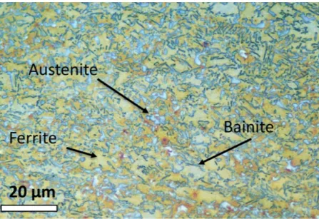
The TRIP780 steel is a low alloy cold-rolled steel. Its name comes from its ability to undergo the TRansformation Induced Plasticity effect and its required ultimate tensile strength (YTS≥ 780 MPa). This ma-terial is well suited for automotive structural and safety parts such as cross members, longitudinal beams, B-pillar reinforcements, sills and bumper reinforcements. It was provided by ArcelorMittal as 2 mm thickness sheets. Its chemical composition (in weight%) is the fol-lowing: Base Fe – 0.209% C – 1.61% Si – 1.64% Mn.
Fig. 1shows the microstructure of TRIP780 steel. It is composed of islands of hard retained austenite (15%) and carbide-free bainite (10–15%) dispersed in a soft ferritic matrix (70–75%). Austenite ap-pears as island-like-grains of 2–3 μm diameter.
Samples of 60 × 60 mm2were cut from the rolled sheet. They were shot peened on one side in a turbine Wheelabrator shot-peening ma-chine with steel shots (hardness 700 HV). Two shot peening conditions were applied: SP1 (shot diameter 400 μm, Almen intensity F19A, cov-erage rate 230%) and SP2 (shot diameter 600 μm, Almen intensity F31A, coverage rate 270%).
2.2. Material characterizations and X-ray diffraction stress analysis Microhardness in-depth profiles were performed using a Shimadzu
indenter. The initial hardness of the as-received material was measured to 270HV0.3 and was constant along the thickness of the material. Microhardness profiles were obtained for SP1 and SP2 conditions by cutting the samples and measuring along the edge.
Texture analysis performed by X-ray diffraction showed that no significant crystallographic texture was present at the surface of the as-received material. X-ray diffraction analysis were performed using a PROTO iXRD portable goniometer, with a spot size of about 2 mm in the center of the plate. Indeed, preliminary measurements demon-strated that residual stresses were homogeneous at the surface of the shot peened plate until 20 mm from the center.
The diffraction peaks of ferrite (α, BCC) and martensite (α′, QC) appearing more or less at the same position and since no peak se-paration has been performed in this study, residual stresses results thus matched to the pseudo-ferritic phases (α + α′). The residual stresses were also determined in the austenitic phase γ (FCC).
Residual stresses analysis was conducted using the sin2(Ψ) method (NF-15305, 2009) with the following parameters:
α + α′: {211}+ lattice planes, Cr Kα anode,
−S1= 1.28 × 10⁻⁶MPa−1, 1/2S2= 5.92 × 10⁻⁶MPa−1;
γ: {311}γlattice planes, Mn Kαanode, −S1= 1.20 × 10⁻⁶MPa−1, 1/2S2= 7.18 × 10⁻⁶MPa−1;
13 Ψ angles were used and peaks were localized with a gaussian fit at 30% height of the peak maximum.
The full width at half maximum (FWHM) profiles were acquired for the pseudo-ferritic phases (α + α′) and the austenitic phase γ (FCC). The volume fraction of retained austenite was determined following ASTM standards (ASTM-E975, 2013) with a Cr anode and a V filter by mea-suring the corresponding intensities of the following peaks in both phases: {220}γ, {200}γand{211}+ ,{200}+ .
Electrolytical polishing was used to remove locally a material layer and thus determine the retained austenite content and the residual stresses in both phases in the sub-surface. The layer removal was con-ducted gradually and was measured at each step by a dial indicator. The estimated measurement accuracy was about 5 μm.
The layer removal can induce a stress relaxation, even greater as the reached depth is significant. Residual stresses results were thus cor-rected by a model suggested bySikarskie (1967):
= × = ×
z z z
z e
( ) ( ) 4 ( 0)
corrected measured measured (1)
where z is the corresponding depth of the measurement, Δz the layer removal thickness, e the initial thickness of the specimen and
= z
( 0)
measured the residual stresses obtained at the surface.
3. Modeling and finite element simulation
A representative finite element modeling of the shot peening process was carried out in order to model the residual mechanical fields from the surface towards the core of the material. A specific material beha-vior law for multiphased TRIP steels has been adapted from the model developed byKubler et al. (2011). The strain sensitivity effect is neg-ligible for TRIP780 steels, therefore it was not considered in the model and the behavior is elastoplastic with time independent martensitic phase transformation. The simulation uses a user subroutine (VUMAT) for the material behavior implemented in Abaqus Explicit. The shot peening process was modeled using finite element method with mul-tiple successive impacts of spheres on a semi-infinite body.
3.1. Constitutive equations for the TRIP steel behavior and identification of model parameters
The material behavior law for TRIP steels is a multiphased model where the elastoplastic behavior is predicted in each phase (ferrite, bainite, austenite and created martensite) and martensitic transforma-tion is taken into account by a transformatransforma-tion kinetic law. Table 1
presents the notations used to formulate the constitutive equations of the model.
For multiphase steel grades containing ferrite (α), bainite (b) and metastable austenite (A) of respective volume fraction Fα, Fband FA, the total strain rate is divided in each constituent, within a small strain assumption, such as:
= + +
E F Fb b FA A (2)
with
+ + =
F Fb FA 1 (3)
In the representation proposed by the model, the retained austenite A includes the non-transformed austenite γ and the created martensite α′ such as A ≡ γ + α′.
With the thermo-elastoplastic behavior of ferrite and bainite, the total strain rate is:
= + + + + + + + + E F F F f f f f ( ) ( ) (1 ) 1 ¯ ( ) b A T ep th epb thb ep th ep th (4)
The martensite α′ of volume fraction f=VVA, is created from the transformation of austenite γ under a thermomechanical loading.
is the elastoplastic strain rate, this the thermal strain rate and ¯Tis
the mean instantaneous transformation strain (MITS) describing a part of the induced plasticity (Kubler et al., 2011).
For the finite element implementation of the behavior law in a VUMAT subroutine, the total strain rate is localized in each constituent using Taylor's assumption:E= = b= A.
The macroscopic stress rate derives from the contribution of the stresses in each constituent such as:
=F +Fb b+FA((1 f) +f +f( )) (5)
The constitutive behavior includes different contributions:
•
Elastoplastic behavior:The elastoplastic behavior is described in each constituent using von-Mises criterion with non-linear hardening.
The linear elastic behavior is isotropic and is described with the shear modulus μ = 80 GPa and Poisson's ratio ν = 0.3. The yield surface is defined by the yield function Y as:
=
Y eq y R (6)
where σyis the yield stress and the von-Mises stress is defined as:
= s X s X
3
2( ): ( )
eq (7)
sis the deviatoric stress tensor. R and Xrepresenting the isotropic and the kinematical hardenings are defined as functions of the plastic strain pand its equivalent value p
eqsuch as: = R Q (1 e b ) 0 . p eq (8) = X 2C X p 3 . p . . (9) where Q0, b, C and Γ are material parameters, and pthe
accumu-lated plastic strain rate.
The incremental elastoplastic behavior is defined by: = lep: ep
(10)
Fig. 1. Optical micrograph of the microstructure of TRIP780 steel. Table 1 Glossary of notations Symbol Definition X Rate of quantity X,X= dX dt
Macroscopic stress tensor
E Macroscopic strain tensor
Local stress tensor
s Deviatoric part of the stress tensor
Local strain tensor
C Fourth order tensor of elastic moduli
lep Fourth order elastoplastic tensor p
eq Equivalent plastic strain
p Accumulated equivalent plastic strain
R Isotropic hardening
X Kinematical hardening tensor
¯ (MITS)T Mean Instantaneous Transformation Strain tensor
θ Volume change accompanying the γ → α′ transformation
eT Deviatoric part of the MITS
Fα, Fb, FA Volume fractions of ferrite, bainite and retained austenite
Using the standard approach for associated plasticity (Lemaitre and Chaboche (1985)), the elastoplastic modulus lepof each constituent
is derived as a function of the hardening parameters: = + l C µ H µ s X s X 9 ( 3 ) ( ) ( ) ep 2 eq2 (11)
where α depends on the yield function: = = < Y Y 1 if 0 0 if 0 (12)
with C the tensor of elastic moduli and H defined as: =
H Rp
eq (13)
•
Mean Instantaneous Transformation Strain (MITS):The MITS ¯T represents the mean contribution of transformation
strain rate over all the activated variants of martensite. It is addi-tively decomposed in a volumic part 1
3 and a deviatoric strain
contribution eT: = + e ¯ 1 3 T T ij ij ij (14) with = = V V ¯ T kk (15)
being the volume variation, resulting from the crystallographic transformation from the austenitic to the martensitic lattice. θ is independent of the stress level and considered as a material data. Including volume variation, the MITS is given as a function of the deviatoric stress in the non transformed austenite sγbyKubler et al. (2011): = +d s +d s s s s ¯ 3 9 16[ ] 27 16 T ij ij 1 ij 2 kl kl ij ki kj (16)
where d1(MPa−1) and d 2(MPa
−2) are two parameters.
•
Transformation kinetics:The martensitic transformation kinetics, i.e. evolution of the volume fraction of martensite f versus the control parameters, is defined within a thermodynamical time-independent framework. Guiheux et al. (2017) completed the transformation kinetics proposed by Kubler et al. (2011), where the transformation kinetics involves Patel-Cohen (Patel and Cohen, 1953) and Olson-Cohen (Olson and Cohen, 1982) evolution laws:
= + f f B T n 1 (__ : __¯ . . . . exp( . ). [1 exp( . )] ) T p p eq p eq eq (17)
where κ, α, β and n are material parameters.
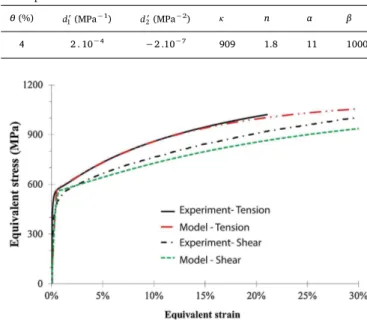
The calibration of the material parameters was carried out with me-chanical tests in tension (monotonic and cyclic) at room temperature coupled with martensitic volume fraction determination vs strain on TRIP780 specimens obtained from a first steel cast. Results from the litterature (Furnemont, 2003) were also used for shear testing. The volume fractions of the initial constituents were Fα= 70%, Fb= 13% and FA= 17% (f = 0). The calibrated material parameters are pre-sented inTable 2, for hardening and inTable 3for the transformation
kinetics. Only the kinematical hardening was considered in the cali-bration (i.e. Q0= 0). The comparisons between experimental and si-mulation data are presented inFigs. 2and3for a monotonic loading. Though phase determination was not available in shear testing, simu-lations are in good agreement with experimental data. The model predicts more phase transformation in tension than in shear testing.
For the TRIP780 steel grade that was used for shot peening, the initial value of retained austenite volume fraction was determined by XRD and was set in the simulation to FA= 13% with Fα= 70% and Fb= 17%. Before shot peening, the simulation considers a constant distribution of constituents in the depth of the modeled medium.
The model is coded in FORTRAN and implemented in a VUMAT
Table 2
Model parameters for the hardening behavior of each constituent
σy(MPa) C Γ Austenite 600 3900 5 Martensite 1400 3000 5 Ferrite 510 3600 10 Bainite 700 4050 5 Table 3
Model parameters for the transformation kinetics
θ (%) d1(MPa−1) d
2(MPa−2) κ n α β
4 2 . 10−4 −2 .10−7 909 1.8 11 1000
Fig. 2. Mechanical stress vs strain response in tension and shear testing.
Experiments vs model with the calibrated parameters.
Fig. 3. Martensitic volume fraction vs total strain. Experiments vs model with
subroutine using ABAQUS Explicit.
3.2. Finite element model for multi-impact shot peening
In order to link the finite element simulation to process parameters such as coverage rate and impact velocities, an a priori estimation of the coverage is needed. The case of a single shot of diameter D impacting at a velocity V is useful to obtain an analytical value of impact radius a using Hertz theory, as developed in A. The impact radius a is given by:
= a D K V E . . 4 2 ¯ s 2 1/5 (18) where K is the impact efficiency ratio, ρsis the density of the material of the shot andE¯is the equivalent Young modulus.
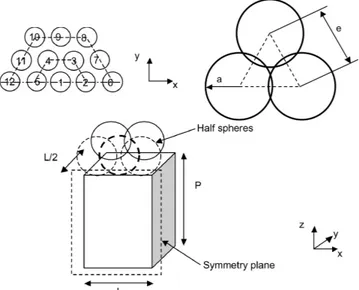
The shot peening process is modeled by the impact of multiple spheres on a plate. Considering an homogeneous repartition of the shot peening flow, a representative volume element of the process can be modeled. A symmetry condition is also considered in order to model halfspace. The plate is restricted to a rectangular box of thickness P, length L and width L/2 as seen inFig. 4. The spheres have only an elastic isotropic behavior (E = 210 GPa, ν = 0.3). The spheres in the plane of symmetry are cut in half and boundary conditions are applied according to the symmetry. The translations of each face of the box are blocked along their normal directions, except the top face. The cutting planes of the half spheres in the plane of symmetry are blocked in translation in direction y. The other spheres are free. In the presented study, the velocity of the shot is initialized on each node of the spheres in direction y (normal impact). The initial velocity for SP1 and SP2 are estimated from the turbine rotation velocity and its diameter, and are set to: V = 60 m/s.
For multi-impact simulations, the spherical pebbles impact the plate according to an hexagonal pattern, where the distance between the center of the closest peebles is equal to e. The impact radius a re-presenting the diameter of the dimple after impact is estimated using Eq.(18).
The coverage rate T defined as the ratio of the impacted area over the total area, is estimated with respect to the distance e (seeFig. 4), the diameter D and the velocity V as:
= = = T S S a e D e K V E 2 3 2 3 . . 4 2 ¯ s impacted total 2 2 1/5 2 (19) Inversing Eq(19), the coverage rate T will give the distance between impacts e for a given media impacting with a velocity V.
Two ranges (nR= 2) around the central impact are modeled al-lowing the simulation of a 19 shot peening process. The mesh consists of C3D8R elements in the impacted material close to the surface and in the shots. At a depth where the residual stresses become negligible, C3D4 elements are used. The mesh size close to the surface is 25 μm.
The contact is defined between the impacted surface (slave surface) and and the shots (master surface) with the penalty method with a normal and tangential behavior and a constant friction coefficient of 0.4. The initial state is free of residual stresses and with an homo-geneous composition (no gradients of behaviors or volume fractions).
The estimated coverage rate(19)is used to set the size L of the rectangular box so that the closest sphere contacts the plate at a dis-tance of the edge of the box. P is also set to obtain a semi-infinite body conditions.Fig. 5presents the adopted mesh. The shooting order has no effect on the averaged results if the results are averaged on a zone bigger than the first range. In this case, the results are averaged over an hexagonal zone corresponding to the last range of the impacted part (hexagon of radius 2e). The mechanical (residual stresses and plastic strain) and microstructural fields (martensitic volume fraction f) are averaged at a depth with respect to the undeformed mesh.
4. Results and discussions
4.1. Experimental results
Fig. 6presents the hardness profiles after shot peening SP1 and SP2 which was performed on the cross sections of shot peened samples; the dashed line represents the base material. Hardening is clearly observed for SP1 condition (respectively SP2 condition) for which the maximum value of 315HV (respectively, 410HV) is reached at the near-surface and decreases until the material hardness at a depth of roughly 50 μm (respectively, 150 μm). These results are in agreement with the lit-erature [Fargas et al., 2015].
The retained austenite fraction was measured by XRD; the absolute accuracy is about ± 3%. Before shot peening, the austenite content is 5% at the surface; it increases up to 12% for depths larger than 50 μm. The lowest value at the surface is due to the processing route as the
Fig. 4. Multiple impact configuration. Numbers indicates the shooting order. e
represents the distance between the center of impacts of radius a.
Fig. 5. Dimensions and finite element mesh of the shot-peened block. nR= 2 in the presented case.
sheets were skin-passed; this has induced martensitic transformation in the near surface. Fig. 7 presents the retained austenite content as a function of depth for both SP conditions. In the first fifty micrometers, it was too weak to be detected by XRD. Then the retained austenite content increases up to its initial value, 12%, at a depth of 100 μm for SP1 condition (respectively 200 μm for SP2). The TRIP effect induced by SP is maximum at the surface; an increase of the shot diameter and the intensity induces an increase of the affected depth (i.e. where the martensitic transformation occurred).
Before SP, the residual stresses in ferritic phases and in austenite were quite low, less than 100 MPa in absolute value.Fig. 8presents the
residual stresses profile for the ferritic phases for both SP conditions. As mentioned in Section 2.2, this is an average value over ferrite, bainitic ferrite and martensite phases as XRD do not allow to separate each contribution. Both profiles are quite similar to those commonly found in the literature. SP1 condition leads to a more intense surface and max-imum compressive stresses than SP2, respectively -380 MPa and -420 MPa for SP1, and -490 and -510 MPa for SP2. Moreover, whereas the compressive stress is rather constant over the first hundred micrometers for SP2, it decreases from the first twenty micrometers for SP1: its value at 250 μm depth is almost null, compared to -200 MPa for the other peening condition.
In austenite, due to its low fraction, stresses could not be determined in the first hundred micrometers as the accuracy was not sufficient. Fig. 9shows that austenite is also in compression; the values are larger than in the ferritic phases, of about 150–200 MPa. The highest com-pressive stresses are observed with the larger shot diameter (SP2) which are 100 MPa higher than the SP1 values. Moreover, the stress has re-turned to zero value at 250 μm for SP1 whereas it is still in high compression for SP2. An inflection point seems to be observed around 120 μm, resp. between 150 and 200 μm, for SP1, resp. SP2; these depths correspond to the point where the retained austenite fraction becomes equal to its initial value of 12%. In agreement with literature, in-creasing the shot diameter induces an increase of the maximum com-pressive stress and the stress peak is shifted towards larger depths. Stress analysis in the austenitic phase seems to show that the stress decrease is more important in the non martensitic transformation af-fected depth.
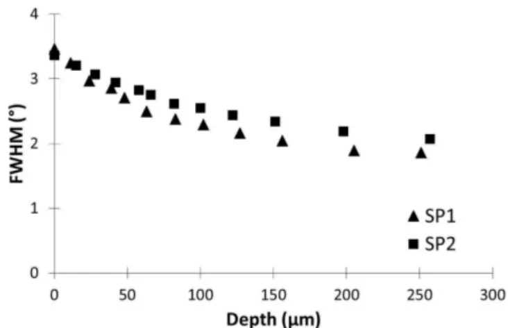
The Full-Width at Half Maximum (FWHM) of diffraction peaks is an indicator of micro-strain and coherent domain size. In the following,
Fig. 6. Microhardness profiles for SP1 and SP2 conditions.
Fig. 7. Profiles of austenite volume fraction for SP1 and SP2 conditions.
Fig. 8. Profiles of residual stresses in ferritic phases ( +
11 ) for SP1 and SP2
conditions.
Fig. 9. Profiles of residual stresses in austenite (11) for SP1 and SP2 conditions.
Fig. 10. Profiles of FWHM in the ferritic phases (α + α′) for SP1 and SP2
only the FWHM corresponding to {211} crystallographic planes of the ferritic phases is presented; there is no austenite diffraction peak at the near surface, as it has been fully transformed into martensite. The FWHM evolution is plotted in Fig. 10 as a function of depth. The maximum value, observed at the surface, is the same for both SP con-ditions. It decreases to a constant value, corresponding to the initial value (before SP), from 200 μm depth for SP1; for SP2, the stable state does not seem to be reached yet at 250 μm depth. From a qualitative point of view, the FWHM is increased compared to the initial value in
the zone where compressive stresses are observed too.
To summarize, all these measurements show an impact of marten-sitic transformation on stresses profiles and FWHM. The depth affected by SP can be defined as the one where the retained austenite fraction is lower than the initial one, that is 100 μm for SP1 and around 200 μm for SP2; it is also associated with the highest compressive stresses and hardness which differ from less than 10% from the maximum value. In the non affected zone, stresses, hardness and FWHM decrease. An in-crease of the shot diameter inin-creases the zone size where the
Fig. 11. Field contours after the impacts for SP1 condition. Macroscopic von Mises stress (MPa), (a) side view from the plane of symmetry, (b) Top view. (c)
Martensitic volume fraction f. The positions of the shots before impact are indicated.
martensitic transformation occurs but it decreases the maximum stress value in the ferritic phases.
4.2. Numerical results and comparison of residual profiles after shot peening The modeled mechanical and microstructural quantities are aver-aged in order to be compared to experimental profiles obtained from X-ray diffraction. After the sequence of impacts on the surface, the fol-lowing quantities averaged on the elements located at a depth z, are analyzed:
•
Volume fraction of retained austenite f × FA;•
Residual stresses in austenite xx zz;•
Residual stresses in ferritic phases comprising ferrite α, bainite b andcreated martensite α′, + +
xx zz ;
•
Residual macroscopic stress Σxx.Fig. 11presents the contours of residual stresses and martensitic volume fraction after impacts for SP1 condition. The averaging region is similar to the hexagonal pattern limited by the center of the impacts as shown inFig. 11b. InFig. 12, it is shown that the average stress is axisymetrical since the σxxcontours look like the σyycontours with a 90° rotation. All the quantities are compared to experimental data in the depth of the sample after shot peening.
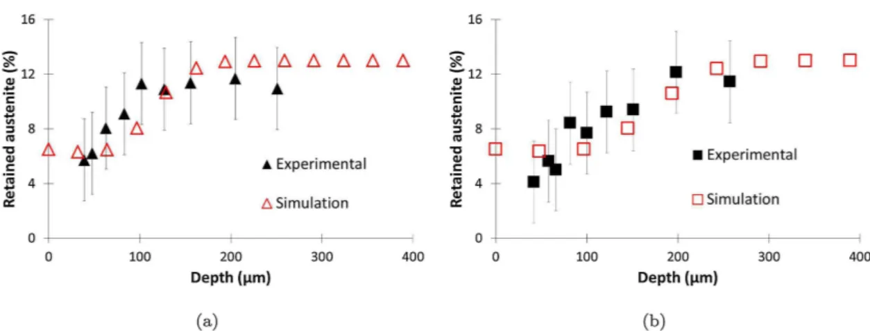
Fig. 13compares the predicted and the experimental profile of re-tained austenite after SP1 (a) and SP2 (b). The model predicts accu-rately the increase of the affected depth for SP2 compared to SP1. The predicted affected depth by martensitic transformation is 150 μm for
Fig. 13. Profile of austenite volume fraction for (a) SP1 and (b) SP2 conditions. Model vs Experimental data.
Fig. 14. Profile of residual stresses: +
SP1 (exp: 100 μm) and 250 μm for SP2 (exp: 200 μm). The profiles are in good agreement with respect to the experimental uncertainty.
In the experimental work, it was not possible to measure the volume fraction of austenite at the surface. However, the model predicts a vo-lume fraction of retained austenite of 6% at the surface. At the surface, where contact between the shots and the plate takes place, this may be attributed to a shear loading where less retained austenite is trans-formed compared to tension (see Fig. 3). Let us also remind that the decrease of retained austenite content at the surface (< 50 μm) prior to shot peening was not considered in the model.
Fig. 14(a-b) presents the residual stresses profiles +
11 for SP1 and
SP2 conditions. A good agreement is found between the model and experimental data. The residual stresses at the surface are identical for SP1 and SP2 conditions. When regarding the affected depth by the compressive residual stresses, the model predicts 300 μm for SP1 and more than 400 μm for SP2. In Fig. 14(c-d), the predicted residual stresses level in the non-transformed austenite 11underestimates the
experimental stress though the affected depth is well predicted. The predicted affected depth by the compressive residual stresses in auste-nite are identical to the one predicted in the pseudo-ferritic phases (α + α′).
4.3. Effect of the martensitic transformation
The adopted model for TRIP steels allows to investigate the effect of
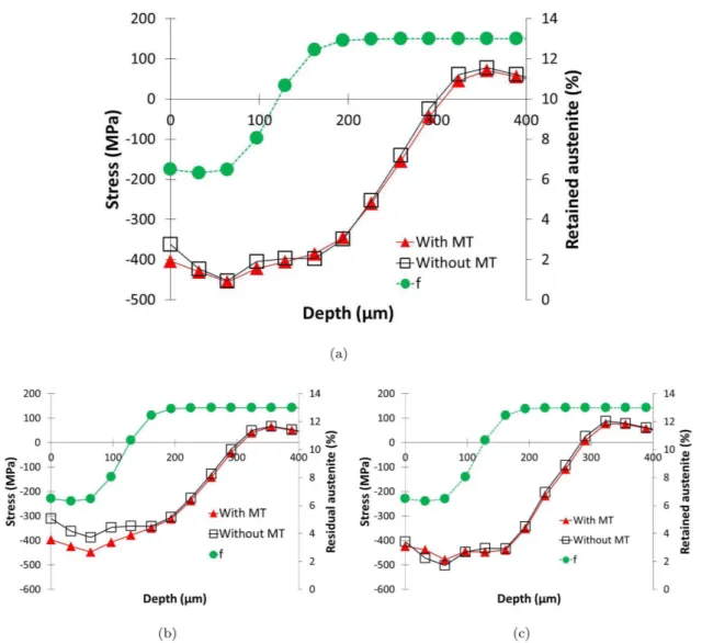
the martensitic transformation by canceling artificially the transfor-mation. The same sequence of impacts was simulated with the extinc-tion of the martensitic transformaextinc-tion, i.e. the impacted surface behaves as a multiphased elastoplastic steel.Fig. 15.a shows the effect of the martensitic transformation on the macroscopic stress profile. A bene-ficial effect is observed in the first 50 μm where the martensitic trans-formation generates more compressive residual stresses (Δσ = 50 MPa). In Fig. 15b, it is observed that with martensitic transformation the pseudo-ferritic phases are more in compression (Δσ = 100 MPa) on a depth of 180 μm corresponding to the depth affected by martensitic transformation. Martensitic transformation has a positive effect on the compressive stress generation. In the retained austenite, the stress profile is only slightly affected by the transformation (Fig. 15c). The martensitic transformation is accompanied by a transformation strain resulting from the Bain strain in each martensitic variant and the ac-commodation inelastic strain in the other phases.Fig. 16shows that the additional transformation strain is maximum at the surface with a value of 5% and decreases to zero until no martensitic transformation takes place at a depth greater than 150 μm. Compared to the total inelastic strain, the contribution of the transformation strain represents 10%.
5. Conclusions
Shot peening was experimentally and numerically investigated in a TRIP780 steel with two shot peening conditions.
Fig. 15. Effect of the martensitic transformation (MT) on the profile of residual stresses (a) macroscopic stress Σ11, (b) +
11 in ferritic phases, (c) 11in austenite for
The experimental X-ray diffraction analysis allows to distinguish the austenitic phase γ and the pseudo-ferritic phases (α + α′). The mar-tensitic peaks have not been separated from the ferritic peaks in this study. However, in a future work it would be interesting to investigate the stress in ferrite and in martensite.
The experiments showed:
•
Martensite appears in the first hundred micrometers and the mar-tensitic transformation is greater when Almen intensity is higher;•
The stress level is determined in the pseudo-ferritic phases (α + α′)and in the austenitic phase γ in depth of the samples. Austenite appears more in compression than the pseudo-ferritic phases. Comparing two SP conditions, though the residual stresses in the pseudo-ferritic phases are similar at the surface, the affected depth is different. It is thus necessary to analyze the stress profiles;
•
The affected depths by residual stresses in the pseudo-ferritic phasesand in austenite are identical. Those affected depths by compressive residual stresses are greater than the affected depth by martensitic transformation.
Numerical simulations by finite element analysis were carried out
by representative dynamical shots on a TRIP780 steel medium, whose behavior is described by an elasto-plastic multiphase model with phase transformation. This model leads to the following conclusions:
•
The martensitic transformation profile is well described by the model for two SP configurations;•
The stress profiles in the pseudo-ferritic phase are well predicted regarding the stress level and the affected depth. The stress in aus-tenite is underestimated. A better model for strain partitioning be-tween phases could help to improve the experimental-modeling agreement;•
By numerically canceling martensitic transformation in the studied TRIP780 steel, it is predicted that martensitic transformation has a beneficial effect on the level of compressive stress in the first 50 μm. An additional transformation strain of 5% contributes to this bene-ficial effect. In a stress fatigue life estimation, this would increase the fatigue life compared to steels without phase transformation. The presented finite element tool can be used to investigate the effect of other microstructural parameters (phase distribution, volume variation) and of different process parameters on the mechanical states after shot-peening. In future studies, the presented numerical tool could also be chained with other simulations of metal forming prior to shot-peening to take into account the initial gradients of microstructure and residual stress fields. Indeed, this could be performed by initializing in-depth profiles of internal variables (plastic strain, martensitic phase transformation) and of mechanical stress fields over which shot peening will be superimposed. Thus, understanding the loading history and their resulting mechanical and microstructural fields would benefit to the fatigue prediction of shot peened parts.Acknowledgments
This work was supported by the French Technological Research Institute for Materials, Metallurgy and Processes (IRT M2P) under the CONDOR project. The authors would like to acknowledge IRT M2P for their financial support and the partners of the project especially PSA Group, ArcelorMittal, Martine Monin, Pierre Osmond and Bastien Weber.
Appendix A. Determination of the impact radius using Hertz theory (Hertz, 1882; Johnson, 1985)
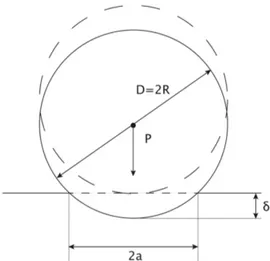
The normal impact of a sphere of diameter D with a semi-infinite medium is considered.
In case of a static indent (seeFig. A.17), the total compression δ is related to the contact size a by:
Fig. A.17. Geometry of a sphere in normal contact with a plane. Fig. 16. Inelastic strain profiles for SP1 condition. Effect of the martensitic
= a D
2
(A.1) In the Hertz theory, the load P, resulting from the pressure forces of the ball on the plate, is linked to δ by:
= P 4 ¯E D
3 2
3/2
(A.2) withE¯ is the equivalent Young modulus defined as a function of the elastic material properties of the shot (subscript s) and of the impacted plate (subscript p): = + E E E ( ¯) 1 s 1 s p p 1 2 2 (A.3) In order to obtain a relationship between the shot peening parameters and the resulting contact area of radius a, an equivalence between an elasto-plastic shock and an elastic one is made. The kinetic energy W of a shot is converted to an elasto-elasto-plastic energy Wepof the impacted material and a energy Wddissipated in the form of temperature and oscillations such as:
= +
W Wep Wd (A.4)
The efficiency of the impact is characterized by the ratio K between the elasto-plastic energy and the total kinetic energy. = K W W ep (A.5) The ratio K was estimated to be 0.8 byJohnson (1972).
The elasto-plastic energy is thus defined as:
= = W K K D V . 1 2mV 12 s ep 2 3 2 (A.6) where ρsis the density of the material of the shot, D its diameter and V its velocity.
For a plastic impact at moderate velocities (up to 500 m/s), impact velocities are small compared to elastic wave speeds. Thus the impact behaviour can be investgated under static conditions. The kinetic energy W is absorbed in local deformation of the two colliding bodies, up to the instant of maximum compression, which is expressed byJohnson (1985):
=
W Pd
0 (A.7)
where the resulting load P is linked to the average dynamic pressure pdby: =
P a p2d (A.8)
By inserting Eqs.(A.1)and(A.8)in Eq.(A.7), the kinetic energy is expressed:
= = W a p a R a p R da 4 a d d 0 2 4 (A.9) By writing the equivalence between Eq.(A.9)and Eq.(A.6), the contact radius is linked to the shot peening parameters by:
= a D K V E . . 4 2 ¯ 2 1/5 (A.10) References
ASTM-E975, 2013. Standard practice for X-ray determination of retained austenite in steel with near random crystallographic orientation.
Bagherifard, S., Ghelichi, R., Guagliano, M., 2012. On the shot peening surface coverage and its assessment by means of finite element simulation: A critical review and some original developments. Appl. Surf. Sci. 259, 186–194.
Chaise, T., Li, J., Nélias, D., Kubler, R., Taheri, S., Douchet, G., Robin, V., Gilles, P., 2012. Modelling of multiple impacts for the prediction of distortions and residual stresses induced by ultrasonic shot peening (USP). J. Mater. Process. Technol. 212 (10), 2080–2090.
Cherkaoui, M., Berveiller, M., Lemoine, X., 2000. Couplings between plasticity and martensitic phase transformation: overall behavior of polycrystalline TRIP steels. Int. J. Plast. (16), 1215–1241.
Cherkaoui, M., Berveiller, M., Sabar, H., 1998. Micromechanical modeling of martensitic transformation induced plasticity (TRIP) in austenitic single crystals. Int. J. Plasticity 14 (7), 597–626.
Fargas, G., Roa, J., Mateo, A., 2015. Effect of shot peening on metastable austenitic stainless steels. Mater. Sci. Engine A 641, 290–296.
Fischer, F., Reisner, G., 1998. A criterion for the martensitic transformation of a micro-region in an elastic-plastic material. Acta Mater. 46 (6), 2095–2102.
Fischer, F., Reisner, G., Werner, E., Tanaka, K., Cailletaud, G., Antretter, T., 2000. A new view on transformation induced plasticity (TRIP). Int. J. Plasticity 16 (7), 723–748.
Fu, P., Zhan, K., Jiang, C., 2013. Micro-structure and surface layer properties of 18CrNiMo7-6 steel after multistep shot peening. Mater. Design 51, 309–314.
Furnemont, Q., 2003. The micromechanics of TRIP-assisted multiphase steels. Université
Catholique de Louvain, Belgium Ph.D. thesis.
Gallitelli, D., Boyer, V., Gelineau, M., Colaitis, Y., Rouhaud, E., Retraint, D., Kubler, R., Desvignes, M., Barrallier, L., 2016. Simulation of shot peening: From process para-meters to residual stress fields in a structure. Comptes Rendus Mécanique 344 (4), 355–374 computational simulation of manufacturing processes.
Gariépy, A., Miao, H., Lévesque, M., 2017. Simulation of the shot peening process with variable shot diameters and impacting velocities. Adv. Eng. Softw. 114, 121–133.
Guagliano, M., 2001. Relating almen intensity to residual stresses induced by shot pe-ening: a numerical approach. J. Mater. Process. Technol. 110 (3), 277–286.
Guiheux, R., Berveiller, S., Kubler, R., Bouscaud, D., Patoor, E., Puydt, Q., 2017. Martensitic transformation induced by single shot peening in a metastable austenitic stainless steel 301LN: Experiments and numerical simulation. J. Mater. Process. Technol. 249, 339–349.
Haidemenopoulos, G., Kermanidis, A., Malliaros, C., Dickert, H., Kucharzyk, P., Bleck, W., 2013. On the effect of austenite stability on high cycle fatigue of TRIP 700 steel. Mater. Sci. Eng. A 573, 7–11.
Halilovič, M., Issa, S., Wallin, M., Hallberg, H., Ristinmaa, M., 2016. Prediction of the residual state in 304 austenitic steel after laser shock peening - effects of plastic deformation and martensitic phase transformation. Int. J. Mechanical Sci. 111-112, 24–34.
Hallberg, H., Håkansson, P., Ristinmaa, M., 2007. A constitutive model for the formation of martensite in austenitic steels under large strain plasticity. Int. J. Plasticity 23 (7), 1213–1239.
Hertz, H., 1882. Über die berührung fester elasticher körper. J. reine und angewandte Mathematik 92, 156–171.
dependence of strain-induced martensitic transformation in TRIP steels and model-ling of transformation kinetics. Int. J. Mech. Sci. 40 (2-3), 173–182.
Jianming, W., Feihong, L., Feng, Y., Gang, Z., 2011 Sep. Shot peening simulation based on SPH method. Int. J. Adv. Manuf. Technol. 56 (5), 571–578.
Johnson, K., 1985. Contact Mechanics. Cambridge University Press.
Johnson, W., 1972. Impact Strength of Materials. Edward Arnold.
Kleber, X., Barroso, S.P., 2010. Investigation of shot-peened austenitic stainless steel 304L by means of magnetic barkhausen noise. Mater. Sci. Eng. A 527 (21), 6046–6052.
Klemenz, M., Schulze, V., Rohr, I., Löhe, D., 2009. Application of the FEM for the pre-diction of the surface layer characteristics after shot peening. J. Mater. Process. Technol. 209 (8), 4093–4102.
Kohar, C.P., Cherkaoui, M., Kadiri, H.E., Inal, K., 2016. Numerical modeling of TRIP steel in axial crashworthiness. Int. J. Plasticity 84, 224–254.
Kubler, R., Berveiller, M., Buessler, P., 2011. Semi phenomenological modelling of the behavior of TRIP steels. Int. J. Plasticity 27 (3), 299–327.
Kubler, R., Berveiller, M., Buessler, P., Lemoine, X., 2010. Semi phenomenological modelling of the behaviour of TRIP steels- application to sheet metal forming. Int. J. Mater. Forming 3 (1), 69–72.
Lemaitre, J., Chaboche, J., 1985. Mécanique des Matériaux Solides, 2nd Edition. Dunod-Paris.
Levitas, V., 1998. Thermomechanical theory of martensitic phase transformations in in-elastic materials. Int. J. Solids Structures 35 (9-10), 889–940.
Ly, A., Findley, K., 2016. The effects of pre-straining conditions on fatigue behavior of a multiphase TRIP steel. Int. J. Fatigue 87, 225–234.
Ma, A., Hartmaier, A., 2015. A study of deformation and phase transformation coupling for TRIP-assisted steels. Int. J. Plasticity 64, 40–55.
Meguid, S., Shagal, G., Stranart, J., 2002. 3d fe analysis of peening of strain-rate sensitive materials using multiple impingement model. Int. J. Impact Eng. 27 (2), 119–134.
Murugaratnam, K., Utili, S., Petrinic, N., 2015. A combined DEM-FEM numerical method for shot peening parameter optimisation. Adv. Eng. Software 79, 13–26.
NF-15305, 2009. Essais non-destructifs - Méthode d’essai pour l’analyse des contraintes résiduelles par diffraction des rayons X. Norme AFNOR.
Novelli, M., Fundenberger, J.-J., Bocher, P., Grosdidier, T., 2016. On the effectiveness of surface severe plastic deformation by shot peening at cryogenic temperature. Appl.
Surf. Sci. 389, 1169–1174.
Olson, G., Cohen, M., 1975. Metal. Trans. 6A, 791–795.
Olson, G., Cohen, M., 1982. Stress assisted isothermal martensitic transformation: ap-plication to TRIP steels. Metal. Trans. A 13A, 1907.
Patel, J., Cohen, M., 1953. Criterion for the action of applied stress in the martensitic transformation. Acta Metal. (1), 531.
Serri, J., Martiny, M., Ferron, G., 2005. Finite element analysis of the effects of marten-sitic phase transformation in TRIP steel sheet forming. Int. J. Mechanical Sci. 47 (6), 884–901.
Sikarskie, D., 1967. On a series form of correction to stresses measured using X-ray dif-fraction. AIME Trans. 239, 577–580.
Stringfellow, R., Parks, D., Olson, G., 1992. A constitutive model for transformation plasticity accompanying strain-induced martensitic transformations in metastable austenitic steels. Acta Metal. Mater. 40 (7), 1703–1716.
Sugimoto, K., Mizuno, Y., Natori, M., Hojo, T., 2017. Effects of fine particle peening on fatigue strength of a TRIP-aided martensitic steel. Int. J. Fatigue 100, 206–214.
Tjahjanto, D., Suiker, A., Turteltaub, S., Rivera Diaz del Castillo, P., van der Zwaag, S., 2007. Micromechanical predictions of TRIP steel behavior as a function of micro-structural parameters. Comput. Mater. Sci. 41, 107–116.
Tomita, Y., Iwamoto, T., 1995. Constitutive modeling of TRIP steel and its application to the improvement of mechanical properties. Int. J. Mechanical Sci. 37 (12), 1295–1305.
Tu, F., Delbergue, D., Miao, H., Klotz, T., Brochu, M., Bocher, P., Levesque, M., 2017. A sequential DEM-FEM coupling method for shot peening simulation. Surf. Coat. Technol. 319, 200–212.
Turteltaub, S., Suiker, A., 2006. A multiscale thermomechanical model for cubic to tet-ragonal phase transformations. Int. J. Solids Struct. 43, 4509–4545.
Xiao, X., Tong, X., Gao, G., Zhao, R., Liu, Y., Li, Y., 2018. Estimation of peening effects of random and regular peening patterns. J. Mater. Process. Technol. 254, 13–24.
Zarka, J., 1990. A New Approach in Inelastic Analysis of Structures. CADLM.
Zhang, J., Lu, S., Wu, T., Zhou, Z., Zhang, W., 2018. An evaluation on sp surface property by means of combined FEM-DEM shot dynamics simulation. Adv. Eng. Softw. 115, 283–296.