Science Arts & Métiers (SAM)
is an open access repository that collects the work of Arts et Métiers Institute of Technology researchers and makes it freely available over the web where possible.
This is an author-deposited version published in: https://sam.ensam.eu
Handle ID: .http://hdl.handle.net/10985/6801
To cite this version :
Tarek BRAHAM-BOUCHNAK, Guénaël GERMAIN, Patrick ROBERT, Jean-Lou LEBRUN, Stéphane AUGER - High pressure water jet assisted machining of duplex steel: machinability and tool life - International Journal of Material Forming - Vol. Volume 3, n°Issue 1 Supplement, p.507-510 - 2010
Any correspondence concerning this service should be sent to the repository Administrator : archiveouverte@ensam.eu
High pressure water jet assisted machining
of duplex steel: machinability and tool life
T. Braham-Bouchnak 1, G. Germain 1*, P. Robert 1, J.L. Lebrun1, S. Auger 2 1 Arts et Métiers ParisTech, CER Angers, 2bd du Ronceray 49000 Angers
2 CETIM, 74 route de la Joneliere 44326 Nantes * guenael.germain@angers.ensam.fr
Abstract
High pressure water jet assisted turning (HPWJAT) consists of projecting a high pressure water jet, up to several hundred bar, into the tool-workpiece interface. The water jet is directed between the chip and the tool affording greater protection of the cutting face and better chip breaking. Comparisons are made between assisted turning using several jet pressures and conventional turning with different cut-ting speeds on the duplex stainless steel, X2CrNiMo22-5. The results show good chip fragmentation and an improvement of tool life with high pressure water jet assistance (HPWJAT). The evolution of the roughness is also investigated. It is shown that it is possible to improve the productivity by using HPWJAT.
INTRODUCTION
Due to environmental and economic con-straints, manufacturers look to save time and reduce manufacturing costs.
Stainless steels are extensively used thanks to their excellent physical and metallurgical prop-erties. Hence, the improved machining of these materials requires the use of new processes that make it possible to increase the degree of chip fragmentation to improve the productivity and/or the tool life without reducing the ma-chined surface quality. High pressure water jet assisted turning (HPWJAT) is one of the main methods used for these purposes. Studies have shown that this technique leads to better control of the chip shape [1-3]. With this process it is not only a question of lubricating the cutting zone, but of directing a high pres-sure water jet between the tool and chip to create a hydrostatic bearing. This improves chip breakage.
Different studies have been carried out to de-termine the effect of cutting fluids on tool wear mechanisms, chip shapes and surface rough-ness, obtained after machining [1-5]. The ef-fects of high and ultra-high pressure water jets directed into the tool chip interface on tool tem-perature, cutting forces, chip shape and surface roughness in turning have been explored by Shet et al [6]. The results show a significant reduction in the tool edge temperature of about 40 to 45%. These authors concluded that the water jet can be used to obtain good heat dis-sipation to control the chip forming process and
to change the cutting process by changing the frictional conditions.
The aim of this study is to highlight the contri-bution of high pressure water jet assisted ma-chining on a duplex stainless steel (X2CrNiMo 22-5). The material has been prepared and supplied by the company GEA Westafalia Se-prator. The increase in productivity is deter-mined by comparing the Taylor experimental curves, with and without high pressure water jet assisted machining.
A comparison is made between the results ob-tained for low pressure cutting (Classical Lubri-cation CL) and those obtained with HPWJAT on cutting forces, surface Roughness (Ra and Rmax criteria), and the observation of the tool wear and tool life.
PRESENTATION OF HPWJAT
1 PRINCIPLE
High pressure water jet assistance consists on projecting a high pressure lubricant jet into a specific location of the cutting area (Figure 1). The jet is uni-directional, with a given flow rate and pressure.
This High Pressure (HP) jet allows more effec-tive lubrication and evacuation of the heat pro-duced during the cutting process, as compared to conventional lubrication. The high pressure lubrication adds the possibility of breaking chips by a mechanical action of the jet independently of the cutting parameters. As a result, the high pressure jet can increase significantly the frag-mentation of chips for fixed cutting parameters. In addition, under certain conditions the HP wa-ter jet can create a film (or a hydrostatic bear-ing) between the chip and the tool which pro-tects the tool. In this case, the life of the tool can be increased significantly.
2 EXPERIMENTAL EQUIPMENT
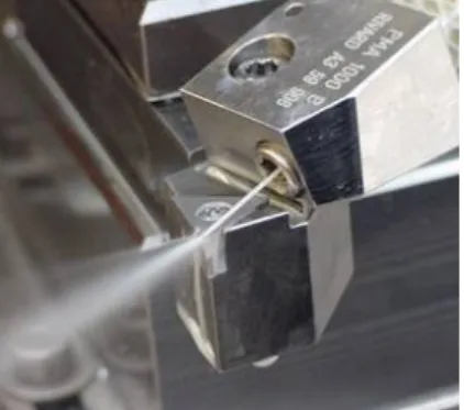
The tests were performed on a numerically controlled Ramo lathe, with a horizontal bench and a high-pressure pump Hammelmann HDP42 at 30 kW. The lubricant used is an emulsion of 5% by volume of QUAKERCOOL 7500 SF with water. The emulsion is recom-mended for very difficult machining of alumi-num and hard steel (some stainless steel...). The HPWJAT tool used was developed in col-laboration with SANDVIK SA with a holder ref-erence DNMG 15 06 08 MF (Figure 2).
Buse
Figure 2: Tool used for high pressure water jet assisted machining test.
The pressure is directly measured in the tool holder by a manometer. The tool is directly posed in a Kistler dynamometer to measure the cutting force during machining.
EXPERIMENTAL STUDY
Tests were conducted using a duplex stainless steel X2CrNiMo22-5 with a hardness of 255 Hv30.
Inserts DNMG 15 06 08 MF (Sandvik) were used and cutting parameters were fixed as fol-lows:
- a feed, f = 0.15 mm.tr-1.
- a cutting depth, ap = 0.5 mm.
- a cutting speed, Vc, which varies depending on the tests to be con-ducted.
The wear tests were carried out in conventional lubrication and HP water jet assistance. The
monitoring cutting force, the surface roughness (Ra and Rmax) and the wear of the inserts (Vb) were investigated during the wear test. Tool life was examined for an average flank wear Vb = 0.1mm.
RESULTS AND DISCUSSIONS
1 CHIP FRAGMENTATION
1.1 Minimal pressure of the assistance
Initial tests were conducted in order to deter-mine the minimum pressure to fragment the chip. Tests were performed with f = 0.15 mm.tr -1, ap = 0.5 mm and Vc = 250 m.min-1, without
lubrication, with a classical lubrication (Low Pressure, CL) and then with a HP lubrication up to 450 bar in increments of 50 bar. For each test, with a machining length of about 20 mm, the morphology of the chip was observed (Fig-ure 3).
a) Dry one long spiral chip
b)Classical Lubrication one long spiral chip
c) P = 50 bar Long Spiral Chips
(100mm)
d) P = 100 bar Long Spiral Chips
(50mm) d) P = 250 bar Fragmented Spiral Chips (10 mm) e) P = 300 bar Fragmented Chips (5mm) Figure 3: Chip morphology obtained by a) dry machining, b) CL machining and c)-e) HPWJAT High pressure
The chip hog from a pressure of 50 bar but the chip length was still too high (about 100 mm) for a good evacuation. The chips present a good fragmentation from a pressure of 250 bar. In this condition, the chips length is about 10mm, therefore this pressure was chosen for testing wear.
1.2 Fragmentation stability
A study of fragmentation stability (P = 250 bar) was conducted by changing the cutting pa-rameters around those fixed. The speed cutting was increased and then decreased by 20%, ditto for the feed speed and the cutting depth. During all these tests, the chip has remained fragmented which leads to assert that fragmen-tation is very stable in this area (0.4 mm < ap <0.6 mm; 0.12 mm.tr-1 < f < 0.18 mm.tr-1, 200 m.min-1 < Vc <300 m.min-1).
2 VCMIN DETERMINATION
A COM approach according to the norm ISO DIN 66-520-4 was conducted to determine a minimal cutting speed Vcmin. Indeed, tests in classical lubrication and in HP water jet assis-tance have been made in increasing the cutting speed from 100 to 450 m.min-1 by level of 25 or
50 m.min-1. For each test, the cutting force was
measured and the morphology of chips was examined. 2000 2100 2200 2300 2400 2500 2600 2700 2800 2900 0 100 200 300 400 500 600 Cutting Speed (m/min) Sp ec if ic c u tti n g p re ssu re , Kct (M P a ) CL HP (300 bar)
Figure 4: Specific cutting pressure with CL and HP 250 bar.
Figure 4 shows a classic behavior: a decrease of the cutting specific pressure Kc with increas-ing speed can be noticed, and then a 'stabiliza-tion' at a speed named Vcmin is observed. On the contrary, the curve HP (300 bar) presents a large disturbance for cutting speeds higher than 300 m.min-1.
Therefore, a minimum cutting speed Vcmin, can be fixed to 200 m.min-1 for tests in
Classi-cal Lubrication and 250m.min-1 for HP (300
bar).
It could be noted that in classic lubrication and whatever the cutting speed, the chip has never been segmented. However, in HP, chips were always fragmented.
3 WEAR TESTS
The wear tests were conducted at three differ-ent cutting speeds with a classical lubrication and a 250 bar HP lubrication. The cutting speeds used are 250, 350 and 450 m.min-1 in
classical lubrication and 350, 400 and 450 m.min-1 in HP 250 bar. A complementary wear
test was conducted at 350m.min-1 with an HP at
350 bar.
3.1 Result of wear test with CL at 250 m.min-1 Wear tests with classical lubrication were con-ducted for a criterion wear Vb = 0.1 mm and a cutting speed of 250 m.min-1. The tool life in
classical lubrication is 34 minutes. This corre-sponds to a length machined of 8 500 m. The surface roughness (Ra and Rmax) remains very stable throughout the test. Indeed, the cri-terion Ra varies between 0.71 and 1.04µm.
3.2 Comparison of CL and HP tests for a cutting speed of 350 m.min-1
For a cutting speed of 350 m.min-1, the
evolu-tion of wear (Vb) with Classical Lubricaevolu-tion and HPWJ at 250 bar is drawn in function of the machining time (Figure 5). These curves allow to determine a tool life (Vb = 0.1 mm) of about 8 min 40s of machining with classical lubrica-tion (CL) and 16 min 45s of machining with 250 bar HP jet, which represents an increase of ap-proximately 93%!
However, It is important to note that a catastro-phic wear (Vb increasing very rapidly) appears from a value of Vb = 0.1 mm. Wear Vb / Machining time 0 0,02 0,04 0,06 0,08 0,1 0,12 0,14 0,16 0,18 0 2 4 6 8 10 12 14 16 18 20 Machining Time (min) We ar Vb (mm) HP (250 bar) CL
Figure 5: Evolution of the average flank wear with CL and HP at 350m.min-1.
The evolution of the roughness has been drawn and shows a fairly good stability of the criterion Ra according to the wear of the tool (Figure 6).
Indeed Ra remains stable between 0.71 and 1.3 μm whatever the mode of machining (CL or HP). The criterion Rmax, initially fairly stable, at around 4.80 m, increases sharply from 4 000 m machined length for HP machining.
The evolution of the cutting force is identical to the evolution of Rmax.
This is due to the degradation of the tool which appears at 4000m machined length
Roughness / Machined length 0 1 2 3 4 5 6 7 8 0 2000 4000 6000 8000 machined length (m) Ro u gh n es s (µm) Ra HP (250 bar) Rmax HP (250 bar) Ra CL Rmax CL
Figure 6: Evolution of the surface state (Ra, Rmax) with CL and HP at 350m.min-1
3.3 Results of wear test in HP at 400 m.min-1 The test wear at 250 bar HP and with a cutting speed of 400 m.min-1 shows a linear evolution
of wear still a time machine of 8 min (Figure 7), or a machined length of 3 200 m. After this time, wear increases sharply announcing a faster deterioration of the tool. The tool life for this HP 250 bar machining at 400m.min-1 is
es-timated at 9 min 30s. Wear Vb / Machining time 0 0,02 0,04 0,06 0,08 0,1 0,12 0,14 0 2 4 6 8 10 12 Machining time (min) We ar Vb (mm)
Figure 7: Evolution of the flank wear in HP at 400m.min-1.
The evolution of the surface state shows a good quality (0.51 <Ra <0.89) despite the wear of the tool (Figure 8).
Roughness / machined length 0 0,5 1 1,5 2 2,5 3 3,5 4 4,5 5 0 1000 2000 3000 4000 5000 machined length (m) Ro u gh n es s (µm) Ra (µm) Rmax (µm)
Figure 8: Evolution of surface state in HP at 400m.min-1.
3.4 Comparison of wear tests at 450 m.min-1 For a cutting speed of 450 m.min-1, a CL and a
HP wear test have been made. The cutting speed is relatively high, so the tool life is very low. Indeed, on Figure 10, we can estimate the tool life at 2 min 40s with CL and 3 min 30s with 250 bar HPWJ. Wear Vb / machining time 0 0,05 0,1 0,15 0,2 0,25 0,3 0 1 2 3 4 5 Machining time(min) we a r Vb (mm) CL HP 250 bar
Figure 10: Evolution of flank wear with CL and HP 250 bar at 450m.min-1.
The surface is quite correct for Ra between 0.81 and 1 μm (Figure 11). However, the crite-rion Rmax increases strongly with the deterio-ration of the tool.
Roughness/ Machining Time 0 1 2 3 4 5 6 7 8 0 500 1000 1500 2000 2500 Machining Time (m) R o ug hne ss (µ m ) Ra CL Rmax CL Ra HP 250 bar
Figure 11:Evolution of Roughness with CL and 250bar HPWJ at 450m.min-1
3.5 Comparison of Taylor Lines
To compare the tools life with classical lubrica-tion and under 250 bar HPWJ, it is interesting to trace the lines of Taylor for these two modes of machining. The results are represented in logarithmic scale on Figure 12.
1
10
100
100
Cutting Speed (m/min)
1000
Tool
Li
fe
(m
in
)
CL
HP 250 bar
Figure 12: Taylor Lines with CL and HP 250 bar.
Figure 12 highlight a tool life improve with HP water jet assistance. Indeed, gains in tool life are 93% for a cutting speed of 350 m.min-1 and
about 30% for a cutting speed of 450 m.min-1. It is important to note that the three points for each type of machining, CL and HP 250 bar, are relatively well aligned. This confirms that Taylor model is appropriate for these tests. The equations of Taylor law, for both types of ma-chining, are:
Taylor Law: n
v.V
C
T= (1)
With Cvand n constant.
T: tool life (min), V: Cutting speed (m.min-1)
In Conventional machining: 302 . 4 11 . 10 . 638 . 7 − = CL CL V T (2)
In High pressure water jet machining at 250 bar, it can be found:
6639 . 5 250 15 250 4.5604.10 . − = HP HP V T (3)
The coefficients of the Taylor Law show, that for a fixed tool life ; the cutting speed can be increased using HP water jet assistance. In-deed, for a tool life of 30 min, the cutting speed should be 260 m.min-1 for CL machining and
320 m.min-1 with the HP 250 bar, so an
in-crease of the cutting speed of 22% is obtained. The evolution of tool life as a function of pres-sure is made on Figure 13.
y = 0,0314x + 8,3174 y = 0,0044x + 2,3564 0 5 10 15 20 25 0 50 100 150 200 250 300 350 400 Pressure (bar) Tool Li fe (mi n ) Vc=350 m.min‐1 Vc = 450 m.min‐1
Figure 13: Evolution of Tool life in function of pressure.
We can notice that the evolution of the tool life with the water jet pressure is linear for the two different cutting speeds. The Y-intercept is equivalent to the CL tool life. From these observations, we can propose a modification of the Taylor law in which we take into account the water jet pressure:
Taylor Law modified: T =Cv.Vn.(A.P+1) (4)
with Cv, n, A constants
The surface is the Taylor Law modified. In our case this law is written:
)
1
.
0038
.
0
.(
.
10
.
638
.
7
11 4.302+
=
−P
V
T
(5)Figure 14: Representation of Taylor law modi-fied and experimental wear tests.
In the figure 14, the surface show the evolution of tool life in function of the cutting speed and the pressure modelled by the Taylor law modi-fied (equation 5) and the black dots correspond to the wear tests results.
It can be noted that there is a good coincidence between experimental points coincide with the modified Taylor law with an error less than 10%. We can therefore conclude that the model predicts well the tool life for different cutting speed and pressure.
The gains due to high pressure are more sig-nificant for low-speed cutting, here 250m.min-1. The high pressure water jet serves to reduce the tool-chip contact area. This was evident from the fact that the chip size (which depends upon the tool-chip contact length) is much smaller at higher pressures. This reduced tool-chip contact length consequently serves to al-leviate the severe thermal/frictional conditions at tool-chip interface. In the highest cutting speed, it was observed an increase in water pressure was not very beneficial in the tool life. This could be due to the reasoning that a high pressure water jet after penetrating to a certain depth into the tool-chip interface is not capable of penetrating any deeper, overcoming the high contact pressures at the tool-chip interface. Moreover, the temperature generated by fric-tion in the secondary shearing zone could in-crease with the cutting speed. The high pres-sure water jet couldn’t dissipate the effective heat in the interface Tool-Chip.
Further investigations need to be carried out to have a better understanding of this phenome-non.
3.6 Interest of a 350 bar pressure on the tool wear
An additional test was conducted with assis-tance at 350 bar and a cutting speed of 350m.min-1. This test can be directly compared
to conventional lubrication test and with assis-tance of 250 bar (Figure 15).
Wear Vb / Machining Time 0 0,02 0,04 0,06 0,08 0,1 0,12 0,14 0,16 0,18 0 2 4 6 8 10 12 14 16 18 20 22 Machining Time (min) We ar Vb (m m) HP (250 bar) CL HP (350 bar)
Figure 15: Flank wear evolution with CL, HP 250 bar and HP 350 bar at 350m.min-1 The tool life is estimated to 19 min 45s with the HP 350 bar which represents an increase of 18% compared to an HP 250 bar and a gain of 130% compared to a conventional machining under Classical lubrication.
This latter test shows that the HP water jet as-sistance is more effective when the pressure is high. The pressure exerted on the tool-chip in-terface reduces the friction tool-chip (hydro-static bearing). In this case, higher is the pres-sure water jet and higher is the protection of the tool. This supposition is in accord with the ex-perimental tests. In fact, for tests with a cutting speed at 350 m.min-1 the tool life is measured at: 8 min 40 s in CL, 16 min 45 s with 250 bar HPWJA (+91%) and 19 min 45s with 350 bar HPWJA (+126%).
But, a catastrophic wear appears for lower flank wear. This is due to a tool pick up which ap-pears at the beginning of the catastrophic wear. This pick up can stem from a mechanical action of the water jet which increases the damage of the tool.
CONCLUSION AND OUTLOOK This study has demonstrated the effectiveness of high pressure water jet assisted machining on a duplex stainless steel (X2CrNiMo 22-5). It is shown that this process results in:
conditions.
- Improved productivity with a cutting speed more important.
It was shown that the chips will fragment with a relatively low pressure but it takes a minimum pressure of 200 bar for the chip fragmentation to be suitable for an industrial process.
For a 250 bar pressure, the tool wear is lower compared to CL, so that the tool life is almost double for a cutting speed of 350 m.min-1. For a
constant tool life, the cutting speed can be in-creased by about 20% with the HP water jet assistance at 250 bar. This implies increased productivity and a sizable reduction in machine time.
Habak et al [7] studied the effect of high pres-sure water jet assistance on the residual stresses in austenitic stainless steel. He showed that:
- On the surface, work hardening decreases if HP Water jet Assisted machining is used compared to dry turning.
- HPWJAT makes it possible to decrease the surface tensile stresses. A reduction of the longitudinal residual stresses value by ap-proximately 20 to 40% can be observed. - The effect of jet pressure on the depth
af-fected by residual stresses and hardening is relatively small.
It is envisaged that the same type of tests (i.e. determination of the residual stress after ma-chining, using X-ray diffraction) will be con-ducted on the duplex stainless steel, discussed here, in order to determine if the same gains can be observed.
It is expected that the productivity can be fur-ther improved with increasing water jet pres-sure. Further test must be considered to show this.
Similarly, fragmentation tests can also be done to highlight the evolution of the chip splitting zone in a (ap / f) diagram, as a function of wa-ter jet pressure.
Acknowledge
This study was undertaken by the Arts et
Métiers ParisTech CER Angers in collaboration
with two industrial partners: CETIM and Westa-falia.
REFERENCE
[1] P. Dahlman, M. Escursell, Int. J. Mach. Tools and Manuf. Vol 44 (2004), pp 10-115. [2] R. Kovacevic, C. Cherukuthota, M. Ma-zurkiewicz, Int. J. Mach. Tools and Manuf. Vol 35 (1995), p1459-1473.
[3] J. Kaminski, B. Alvelid, J. Mat Proc. Tech. Vol. 106 (2000). P68-73.
[4] R.F Avila, A.M Abuso, J. Mat. Proc. Tech. Vol. 119 (2001), p21-26
[5] J.M. Viera, A.R. Machado, E.O. Ezugwu, J. Mat. Proc. Tech. Vol 116 (2001), p.244-251 [6] C. Shet, X. Deng, A.E. Eayoumi, Int. J.
Mech. Sci. Vol. 45 (2003), p1201-1228. [7] M. Habak, J.L. Lebrun, C. Fischer, Mat. Sci.