Science Arts & Métiers (SAM)
is an open access repository that collects the work of Arts et Métiers Institute of Technology researchers and makes it freely available over the web where possible.
This is an author-deposited version published in: https://sam.ensam.eu Handle ID: .http://hdl.handle.net/10985/10336
To cite this version :
Komi SOHO, Farid ABED-MERAIM, Xavier LEMOINE, Hamid ZAHROUNI - Multiscale finite element simulation of forming processes based on crystal plasticity Key Engineering Materials -Vol. 611-612, p.545-552 - 2014
Any correspondence concerning this service should be sent to the repository Administrator : [email protected]
Multiscale finite element simulation of forming processes based on
crystal plasticity
Komi Soho
1, 3, a, Farid Abed-Meraim
1, 2, 3, b, Xavier Lemoine
1, 2, c, Hamid
Zahrouni
1, 3, d1 Laboratoire d’Étude des Microstructures et de Mécanique des Matériaux (LEM3), UMR CNRS
7239, Ile du Saulcy F-57045, Metz Cedex 01, France.
2Arts et Métiers ParisTech, 4 rue Augustin Fresnel, 57078 Metz Cedex 3, France. 3DAMAS, Laboratory of Excellence on Design of Alloy Metals for low-mAss Structures,
Université de Lorraine, France.
a[email protected], b[email protected], c[email protected]
,
Keywords: crystal plasticity – self-consistent homogenization – finite elements –
elasto-plasticity – coupling – sheet metal forming processes.
Abstract. For the numerical simulation of sheet metal forming processes, the commercial finite element software packages are among the most commonly used. However, these software packages have some limitations; in particular, they essentially contain phenomenological constitutive models and thus do not allow accounting for the physical mechanisms of plasticity that take place at finer scales as well as the associated microstructure evolution. In this context, we propose to couple the Abaqus finite element code with micromechanical simulations based on crystal plasticity and a self-consistent scale-transition scheme.
This coupling strategy will be applied to the simulation of rolling processes, at different reduction rates, in order to estimate the evolution of the mechanical properties. By following some appropriately selected strain paths (i.e., strain lines) along the rolling process, one can also predict the texture evolution of the material as well as other parameters related to its microstructure. Our numerical results are compared with experimental data in the case of ferritic steels produced by ArcelorMittal.
Introduction
Although commonly used for the simulation of sheet metal forming processes, the traditional commercial finite element (FE) codes have several limitations. These restrictions are mainly related to the built-in constitutive models, which are essentially phenomenological thus not accounting for the physical mechanisms of plasticity and the underlying microstructure evolution.
To overcome some of these limitations, an alternative would be to couple these FE simulation codes with micromechanics-based behavior models. The latter are generally based on crystal plasticity, for the single crystal constitutive equations, and a scale-transition scheme (e.g., the self-consistent model), for the overall response of the polycrystalline aggregate.
In the literature, several attempts have been made in order to implement constitutive models based on crystal plasticity (strain-rate dependent or strain-rate independent) into each integration point of FE calculations.
For strain-rate dependent constitutive models, we can mention, among others, the recent works by Segurado et al. [1], who embedded the visco-plastic self-consistent formulation in implicit finite elements and by Zhang et al. [2], who proposed an effective semi-implicit integration scheme for rate dependent crystal plasticity using explicit FE codes. For strain-rate independent behavior models, several contributions can be found in the literature, among which the works by Scacciatella [3], in the framework of small-strain elasto-plasticity, and by Zattarin [4], in the large-strain framework.
However, the main drawback of such direct coupling approaches is the computation time that is relatively high. In fact, the CPU time in a polycrystalline model is generally proportional to the number of constituent grains (it also depends on the constitutive law adopted for the crystallographic slip), and this model is called at each integration point. Accordingly, the CPU time required for FE calculations based on a polycrystalline model is extremely high as compared to that associated with a phenomenological model.
For the above-mentioned reasons, another strategy is proposed in the current work, in which the polycrystalline model and the FE simulation codes Abaqus and LAM3 will be coupled in an indirect way. This technique will be applied to simulate rolling processes, at different reduction rates, and to estimate the evolution of the mechanical properties. By following some appropriately selected strain paths (i.e., strain lines) along the rolling process, we are also able to predict the texture evolution of the material as well as other parameters related to its microstructure.
Constitutive model
First, it is necessary to specify the assumptions on which the behavior of the material at the grain scale is based. The single crystal constitutive law is assumed to be elastic-plastic, with the plastic deformation only due to crystallographic slip; the other modes of inelastic deformation, such as twinning or phase transformation, are not taken into account in the scope of this study. The local incremental elasto-plastic constitutive law is defined by means of the tangent modulus l relating the nominal stress rate n to the velocity gradient g:
n = l : g (1) The above velocity gradient is the sum of the total strain rate and spin. The latter two parts can be further divided into an elastic part with the superscript e and a plastic one with superscript p. The plastic parts (plastic strain rate and plastic spin) are related to the slip rates g by:
p e g g p e g g γ γ
g g d = d - d = R w = w - w = S (2) where g R and gS denote, respectively, the well-known symmetric and anti-symmetric parts of the Schmid tensor associated with a given slip system g. A rate independent regularization law [5] is adopted for the determination of the slip rates:
g g g k (3) g g g g 0 1 2 gg g c 1 1 1 1
k (1 tanh(k )) (1 tanh(k ( 1))) (1 tanh(k ))
H 2 2 2
(4)
where H is the self-hardening term and „tanh‟ stands for the hyperbolic tangent function. Eq. (4) gg aims at modeling at best a threshold (smooth approximation to the discontinuous step function) without having the numerical problems inherent to the use of sharp functions, and combined with
g g g k
provides a regular form of the Schmid law. The expression of the elasto-plastic tangent
modulus is then derived as follows (see [6,7]):
ijkl ijkl ik lj il kj ik lj il jk g g g gh h h ijpq pq ip pj ip pj mn mnkl mn kl 1 1 l C ( ) ( ) 2 2 (C R S S )M k R (C ) (5)
This tangent modulus is composed of elastic and plastic parts, where several convective terms appear due to the large-strain framework. The evolution law of the critical shear stress, in terms of the slip rates, can be expressed as follows (see [6,7]):
nslip g gh h c h 1 H
(6) with gh gh h c h nslip gk k k 1 1 H a ( 2y ) L 2 a
(7)where is a constant related to the stability of dislocation configurations, is the shear modulus, and agh is the anisotropy interaction matrix.
To derive the overall response of the polycrystalline aggregate, the self-consistent scale-transition scheme is used (see [6,7] for more details). Accordingly, the macroscopic behavior law linking the macroscopic fields – nominal stress rate N and velocity gradient G – by means of the yet-unknown macroscopic tangent modulus L has the same incremental form as that of the single crystal (Eq. (1)):
N = L : G (8) These macroscopic fields (i.e. velocity gradient and nominal stress rate) are defined as the volume averages of their microscopic counterparts:
v v 1 1 dv, dv V V
G g N n (9)Indirect coupling strategy applied to the polycrystalline plasticity model
As discussed before, we adopt a strategy of indirect coupling [8] between the FE codes Abaqus and LAM3 and the polycrystalline plasticity model, which has been described just above in section 2. This consists in performing the following steps:
An initial FE calculation that simulates a forming process. In this preliminary simulation, the material parameters are identified with a phenomenological law.
At the end of this preliminary phenomenological FE simulation, the loading history at some appropriately selected material points is recorded.
Then, the above-extracted loading history will serve as prescribed loading for the subsequent simulation, which is based on the polycrystalline model alone (i.e., outside of the FE environment).
In what follows, we will denote by „FEC path‟ the loading path that is extracted from the FE calculation, and by „Linear path‟ the monotonic or sequential loading path that is applied directly to the polycrystalline model (i.e., without using any preliminary FE calculation).
Applications
Indirect coupling: Application to simple loading paths
For the simulation of simple loading paths in the FE code Abaqus, the eight-node reduced-integration C3D8R element is used. Also, the material behavior is taken elasto-plastic with isotropic hardening, with the hardening curve given experimentally. For the polycrystalline model, the identified material parameters are reported in Table 1.
Table 1: Identified material parameters for a ferritic steel.
Parameters [MPa] [nm] [microns] Grains
Value 100 100 3.25 20 5000
where 0 is the initial critical shear stress, g the parameter related to the mean free path of 0 dislocations, y the critical annihilation distance of dislocations and c D the average grain size.
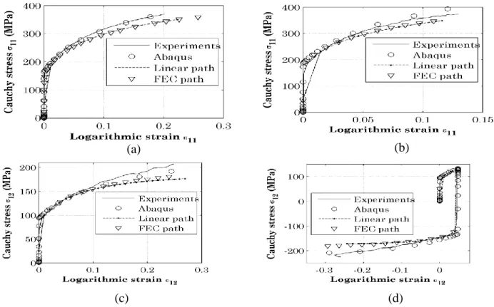
In Fig. 1, we compare the polycrystalline model results corresponding to two different ways of prescribing the loading path, namely the loading path extracted from the preliminary FE calculation „FEC path‟, and the direct application of propositional loading path „Linear path‟. Then, these polycrystalline results are compared to experimental data and Abaqus calculation.
For the four strain paths reported in Fig. 1, namely uniaxial tension, plane strain tension, simple shear, and Bauschinger (reverse) shear, the results of the polycrystalline model are the same for both definitions of the applied loading path, i.e. „FEC path‟ and „Linear path‟. This allowed us to validate our numerical algorithm. The difference between Abaqus results and those of the polycrystalline model is attributable to the material behavior adopted in the FE calculations. In the latter, the hardening is assumed isotropic, while the actual material anisotropy is accounted for in the polycrystalline model along with the associated texture evolution.
Fig. 1. Stress-strain response. (a) Uniaxial tension; (b) Plane strain tension; (c) Simple shear; (d) Bauschinger (reverse) shear.
(a) (b)
Indirect coupling: Application to rolling skin pass processes
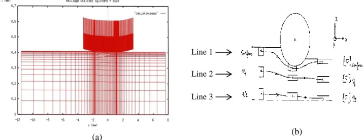
The mesh of the metal sheet and the roll are represented in Fig. 2a, while the strain lines are defined in Fig. 2b. Note that the rolling calculations are performed using the finite element code LAM3 with stationary method.
Once again, the material behavior is assumed elasto-plastic with isotropic hardening, with the hardening curve given experimentally.
Fig. 2. (a) Representation of the mesh of the metal sheet and the cylinder; (b) Position of strain lines.
For the polycrystalline model, the identified material parameters are reported in Table 2. Table 2 : Identified material parameters for a high strength low alloy steel.
Parameters [MPa] [nm] [microns] Grains
Value 120 90 3.25 20 5000
where 0 is the initial critical shear stress, g the parameter related to the mean free path of 0 dislocations, y the critical annihilation distance of dislocations and c D the average grain size.
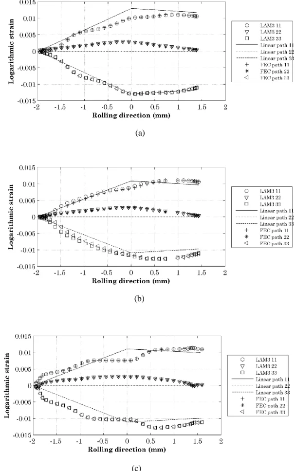
In Figs. 3 and 4, we compare, on a skin pass process, the polycrystalline model results corresponding to the two above-described techniques of loading path application, namely the indirect coupling strategy with the associated loading path extracted from the preliminary FE calculation „FEC path‟, and the direct application of propositional loading path „Linear path‟. These polycrystalline results are also compared to the LAM3 FE calculations (see Figs. 3-4).
From Fig. 3, we can observe that the indirect coupling method along with the associated loading path allows us to follow the strain evolution of the material under roll gap, while the linear loading path method only gives a rough approximation of this evolution. Similar observations can be drawn from Fig. 4, where the indirect coupling method is shown to provide stress evolutions in better agreement with the LAM3 FE results. The difference between the polycrystalline model results and those yielded by the LAM3 FE calculations is also due to the fact that in the latter, the material is assumed isotropic, while in the former, its anisotropy is accounted for along with the associated texture evolution.
Line 1 Line 2 Line 3
Fig. 3. Strain evolution along the rolling direction for each strain line. (a) Line 1; (b) Line 2; (c) Line 3.
(a)
(b)
Fig. 4. Stress evolution along the rolling direction for each strain line. (a) Line 1; (b) Line 2; (c) Line 3. (a) (b) (c)
Conclusion
In this work, we developed a method of indirect coupling between the FE codes Abaqus and LAM3 and the polycrystalline plasticity model. This method consists in performing a preliminary FE calculation, from which the loading history at some appropriately selected material points is extracted and recorded. The latter will serve to define the loading path to be applied in the subsequent polycrystalline model simulation.
In order to validate this strategy and the associated numerical algorithm, it was first applied to simple loading paths (uniaxial or plane strain tension, simple or Bauschinger (reverse) shear) and then to more complex strain paths that are extracted from skin pass rolling simulations. It is shown that the indirect coupling strategy has several advantages. As compared to a linear loading path method, it can adequately represent the phenomena that occur in a metal sheet under the roll gap.
However, the drawback of this coupling is that it relies on a preliminary FE calculation, in which the material behavior is represented by a phenomenological law. Accordingly, the accuracy of the subsequent micromechanical simulation will depend on the choice of the earlier phenomenological model.
In future works, the texture evolution of the material throughout its loading history will be compared to experimental results.
References
[1] J. Segurado, R. A. Lebensohn, J. Llorca, and C. N. Tomé, “Multiscale modeling of plasticity based on embedding the viscoplastic self-consistent formulation in implicit finite elements,”
Int. J. Plast., vol. 28, no. 1, pp. 124–140, 2012.
[2] H. Zhang, X. Dong, Q. Wang, and Z. Zeng, “An effective semi-implicit integration scheme for rate dependent crystal plasticity using explicit finite element codes,” Comput. Mater. Sci., vol. 54, pp. 208–218, 2012.
[3] E. Scacciatella, “Intégration d‟un modèle de comportement élastoplastique à transition d'échelle dans un code de calcul de structures par éléments finis,” Ph.D. Thesis, Université de Metz, 1994.
[4] P. Zattarin, “Etude de l‟intégration d'un modèle polycristallin dans un code d'élements finis en élastoplasticité,” Ph.D. Thesis, Université de Metz, 2000.
[5] G. Franz, F. Abed-meraim, and M. Berveiller, “Strain localization analysis for single crystals and polycrystals : Towards microstructure-ductility linkage,” Int. J. Plast., vol. 48, pp. 1–33, 2013.
[6] J. P. Lorrain, “Critère de ductilité basé sur la perte d‟ellipticité du module tangent élastoplastique deduit d'un modèle autocohérent,” Ph.D. Thesis, Ecole Nationale Supérieure d‟Arts et Métiers, 2005.
[7] G. Franz, “Prédiction de la limite de formabilité des aciers multiphasés par une approche micromécanique,” Ph.D. Thesis, Ecole Nationale Supérieure d‟Arts et Métiers, 2008.
[8] S. R. Kalidindi and L. Anand, “An appoximate procedure for predicting the evolution of crystallographic texture in bulk deformation processing of FCC metals,” Int. J. Mech. Sci., vol. 34, pp. 309–329, 1992.