THÈSE
En vue de l’obtention du
DOCTORAT DE L’UNIVERSITÉ DE TOULOUSE
Délivré par l'Université Toulouse 3 - Paul Sabatier
Présentée et soutenue par
Ramon ANDREU ALTAVA
Le 17 février 2020
Calcul du Profil Optimal d'un Aéronef dans les Phases de
Descente et d'Approche
Ecole doctorale : AA - Aéronautique, Astronautique Spécialité :
Unité de recherche : Thèse dirigée par
Daniel DELAHAYE et Thierry MIQUEL
Jury
M. Damian RIVAS, Rapporteur M. Eric FERON, Rapporteur Mme Itoh ERI, Examinatrice M. John HANSMAN, Examinateur M. Panagiotis TSIOTRAS, Examinateur M. Daniel DELAHAYE, Directeur de thèse M. Thierry MIQUEL, Co-directeur de thèse
Contents
List of Acronyms xiv
R´esum´e xxiii Abstract xxv 1 Introduction 1 1.1 General Introduction . . . 2 1.2 Thesis contributions . . . 4 1.3 Outline . . . 5
2 State of the Art 6 2.1 Introduction to Flight Management System . . . 7
2.1.1 FMS role in the cockpit . . . 7
2.1.2 Flight Deck Evolutions on Airbus Aircraft . . . 8
2.2 FMS Vertical Profile Computation . . . 10
2.2.1 Vertical path construction . . . 10
Contents v
2.2.2 Approach Path . . . 11
2.2.3 Step-Down versus Continuous Descent Operations . . . 11
2.2.4 Theoretical Descent Path . . . 12
2.2.5 FMS Predictions and Guidance on the Vertical Plane . . . 13
2.3 Energy Management . . . 15
2.3.1 Definition . . . 15
2.3.2 High and Low Energy Management in Approach . . . 16
2.4 From FMS Theory to Standard Operating Procedures . . . 17
2.5 Optimal Control Theory . . . 20
2.5.1 Numerical Methods Applied to Optimal Control Problems . . . 22
2.6 Trajectory Optimization Literature Review . . . 24
2.6.1 Research Approach . . . 27
2.7 Basics of the A* algorithm . . . 28
2.7.1 Variants of the A* algorithm . . . 29
2.8 Conclusion . . . 30
3 Mathematical Model 31 3.1 Aircraft Equations of Motion . . . 32
3.1.1 Time-dependent equations of motion . . . 32
3.1.2 Distance-dependent equations of motion . . . 33
3.2 Performance Models . . . 36
3.2.1 Navigation Database (NDB) . . . 36
3.2.2 Performance Database (PDB) . . . 37
3.2.3 Operational Constraints . . . 38
3.3 Airbus FMS Performance Model . . . 39
3.4 Performance Computational Model Validation . . . 40
Contents vi
3.6 Optimal Control Theory . . . 45
3.7 Conclusion . . . 46
4 Optimal Arrival Trajectories with A* Algorithm 47 4.1 The A* algorithm . . . 48
4.2 Implementation of A* to trajectory optimization . . . 48
4.3 Search space generation . . . 50
4.4 Search space pruning . . . 51
4.5 Node generation process . . . 52
4.5.1 Design of the approach phase . . . 55
4.6 Data structures of open and closed lists . . . 57
4.7 Control variables discretization . . . 58
4.7.1 Energy share factor (ESF ) . . . 58
4.7.2 Airbrakes extension . . . 60
4.7.3 Total flight path angle (γT) . . . 61
4.7.4 Flap configuration changes . . . 61
4.7.5 Discretization error quantification and sensitivity analysis . . . 61
4.8 The heuristic function . . . 63
4.8.1 Properties of the heuristic . . . 63
4.8.2 Definition of the heuristic for trajectory optimization problems . . . 64
4.8.3 Manhattan-distance based heuristic . . . 66
4.8.4 Flight Performance Heuristic . . . 67
4.9 Conclusion . . . 69
5 Results and discussions 71 5.1 Test parameters . . . 72
Contents vii
5.2.1 Trajectory computation using BADA model . . . 75
5.3 Case study II: Los Angeles (KLAX) arrival . . . 80
5.3.1 Selection of the arrival procedure . . . 80
5.3.2 Trajectory comparison with a certified FMS . . . 82
5.3.3 Assessment of the trajectory in A320 flight simulator . . . 86
5.4 Case study III: Aircraft high-energy condition . . . 89
5.4.1 Aircraft high-energy condition in approach . . . 89
5.4.2 Flight strategy comparison . . . 90
5.5 Discussion of the results . . . 93
6 Energy-Limit Trajectories 96 6.1 The energy-limit trajectory concept . . . 97
6.1.1 Purpose of the function . . . 97
6.1.2 Mathematical formulation . . . 98
6.2 Case study at KLAX airport . . . 101
6.2.1 Initial parameters of the simulation . . . 101
6.2.2 Operational Assessment in the flight simulator . . . 104
6.2.3 Visualization of the energy-limit trajectory . . . 107
6.2.4 Conclusion . . . 110
7 Conclusion 112 7.1 Achievements . . . 113
7.2 Enablers for this type of flight operation . . . 113
7.3 Perspectives and future work . . . 114
7.3.1 Flight operations perspective . . . 114
7.3.2 Model improvements . . . 115
Contents viii
7.3.4 From the conception towards the industrial application . . . 116
7.4 Wrap-up . . . 117
APPENDICES 118
A Appendix A: Reference frames and equations of motion 118
A.1 Reference frames and equations of motion . . . 119
B Appendix B: Atmospheric Model 122
B.1 The atmospheric model . . . 123
C Appendix C: Gas Emissions Model 125
C.1 Gas emission model . . . 126
List of Figures
2.1 Airbus Cockpit evolution. Source: Airbus Photolib repository. . . 9
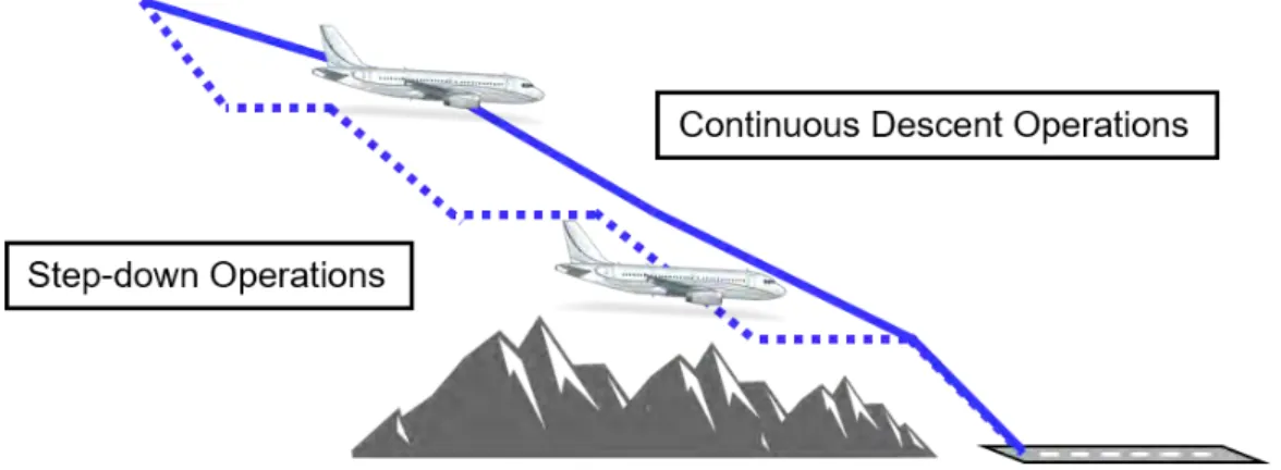
2.2 Traditional Step-Down Operations (dashed line) compared with Continuous Descent Operations (CDO) (solid line) . . . 11
2.3 Typical Flight Management System (FMS) Vertical Profile . . . 13
2.4 FMS sub-mode request depending on altitude error . . . 15
2.5 Reservoir analogy applied to aircraft Energy Management [1]. . . 15
2.6 Typical definition of stabilization point. . . 17
2.7 Vertical deviation on Primary Flight Display (PFD) . . . 19
2.8 Optimal Control Problems classification . . . 21
3.1 Representation of total flight path angle (γT). . . 35
3.2 Glide Slope beam limitation on final approach. . . 37
3.3 Models contained in a Performance Database (PDB) . . . 39
3.4 Altitude (upper) and speed (bottom) profile. . . 41
3.5 Profile comparison between PSIMU and A* developed model. . . 42
3.6 Fuel and time comparison between PSIMU and A* developed model. . . . 42
List of Figures x
4.1 A* progressive search space generation. . . 50
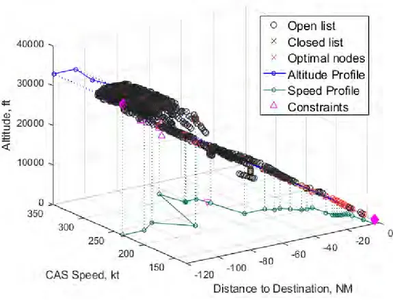
4.2 The search space at completion of the algorithm run. . . 51
4.3 Node generation in the presence of constraints. . . 52
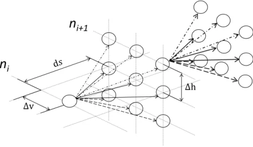
4.4 Neighborhood zone defined around an already existing node (gray-stripped node), which is at the center of the ellipsoid. The next node ni+1, generated
from the current node ni, falls in the zone. . . 53
4.5 Issues associated to the neighborhood area in the vicinity of a constraint. . 54
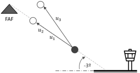
4.6 Several strategies for flight path construction on final approach. . . 55
4.7 Several strategies for flight path construction on final approach: u1 idle thrust on glide, u2 constant speed on glide and u3 constant speed idle thrust. 56
4.8 Impact of 10% energy share increments on altitude and speed for ESF > 0.1. The speed target is 250 knots; small values of ESF lead to long distances while higher values yield shorter distances. . . 59
4.9 Impact of 10% energy share increments on altitude and speed for ESF < 0. The speed target is 300 knots; small negative values of ESF lead to long distances while higher values yield shorter distances. . . 59
4.10 Airbrakes and flap control lever on Airbus aircraft. . . 60
4.11 Impact of discretization in node generation process. Comparison of A* and corrected A* calculations to Runge-Kutta integration. . . 62
4.12 Triangle inequality property of consistent heuristics. . . 64
4.13 Comparison of three type of segments: geometric (dashed line), level-off plus idle (solid line) and level-off plus full airbrakes extension (dotted-dashed line). 65
4.14 Fuel consumption and time flight performance comparison. . . 65
4.15 Comparison between Manhattan (solid line) and euclidean distance (dash-dotted line) . . . 66
4.16 Flight performance heuristic using Base of Aircraft Data (BADA): com-putation of altitude and speed profiles. For each node of the graph, the heuristic estimation is the cost from the current node to the target node. Linear interpolation to obtain this value. . . 67
4.17 Fuel evolution of flight performance heuristic using BADA. . . 68
List of Figures xi
4.19 Admissibility criterion of the heuristic function. . . 69
5.1 APPR ILS-18R. Source: NavBlue. . . 74
5.2 BOOVE4 Standard Terminal Arrival Route (STAR). Source: NavBlue. . . 75
5.3 KDFW case study: Altitude and speed profile. . . 76
5.4 KDFW case study: Fuel consumption and flight time. . . 76
5.5 KDFW case study: Control variables. . . 77
5.6 KDFW case study: Lateral path. . . 78
5.7 KDFW case study: Vertical visualization. . . 78
5.8 Flight plan preparation for KDFW arrival procedure. . . 79
5.9 Gas emissions comparison for KDFW case. . . 79
5.10 APPR ILS-24L. Source: NavBlue. . . 81
5.11 SEAVU2 STAR. Source: NavBlue. . . 82
5.12 Altitude and speed profile comparison between the reference profile com-puted by the FMS and the optimal one comcom-puted by the A* algorithm. . . 83
5.13 Control variables values comparison between the reference profile computed by the FMS and the optimal one computed by the A* algorithm. . . 83
5.14 KLAX case study: Lateral path visualization. . . 84
5.15 KLAX case study: Vertical path visualization. . . 84
5.16 FMS and A* gas emissions comparison for KLAX case study. Note that, for confidentiality reasons, the computed values can not be disclosed. . . . 85
5.17 Flight plan preparation for KLAX arrival procedure. . . 86
5.18 Auto-flight and thrust levers setting for the simulation tests. . . 87
5.19 Altitude profile comparison between the computed trajectory and the actual one flown in the flight simulator. . . 87
5.20 Speed profile comparison between the computed trajectory and the actual one flown in the flight simulator simulator. . . 88
5.21 Flight strategy 1: Altitude and speed profiles. The aircraft is too fast and too high. Flap configuration extensions are marked with numbers on the altitude profile. Priority given to deceleration. . . 90
List of Figures xii
5.22 Flight strategy 1: Flight control values. The extension of airbrakes is
min-imized while flap extensions are anticipated. . . 91
5.23 Flight strategy 2: Altitude and speed profiles. The aircraft is too fast and too high. Flap configuration extensions are marked with numbers on the altitude profile. Priority given to descent. . . 92
5.24 Flight strategy 2: Flight controls values. Airbrakes extended while required and flap extensions are delayed. . . 92
6.1 Non-stabilized approach as a result of strong tailwinds. . . 98
6.2 Influence of wind in the calculation of the trajectory. . . 102
6.3 Altitude and speed profile for the energy-limit trajectory. . . 102
6.4 Control variables for the energy-limit trajectory. . . 103
6.5 Energy-limit flight controls sequence. A, B, C and D represent the sequence of actions to change from clean to landing configuration. . . 104
6.6 EFIS and MCDU display during the simulation tests. . . 105
6.7 Energy-limit strategy sequence. . . 106
6.8 Operational use of the energy-limit trajectory. Here, the minimum distance computed by the energy-limit trajectory is displayed as the radius of the circle centered at the stabilization gate. . . 107
6.9 Visualization of the energy-limit trajectory through the energy-limit arc. . 108
6.10 Energy-arc (red-dashed arc) seen from the top. For a given aircraft altitude and speed, a stabilized approach is possible as long as the aircraft is beyond the arc. . . 109
6.11 Energy-arc in a 3-D environment. The altitude profile shown in blue repre-sents the last trajectory that stabilizes the aircraft. As soon as the aircraft traverses the energy-arc, the approach is non-stabilized. . . 109
7.1 Schema of an artificial neural network. . . 116
A.1 Forces applied on aircraft during descent. . . 119
List of Tables
2.1 Aircraft state at the stabilization point. . . 16
4.1 Comparison of operation costs for typical data structures. . . 57
5.1 General simulation parameters for the case studies. . . 72
5.2 Case study I: Aircraft initial and final state. . . 73
5.3 List of constraints with waypoint labels for KDFW case. . . 73
5.4 KLAX case study initial and final conditions. . . 80
5.5 List of constraints with waypoint labels for KLAX case. . . 80
5.6 Initial and final states used for the computation of the high-energy case study. 89 6.1 Parameters of the simulation. . . 101
List of Acronyms
ACARS Aircraft Communication Addressing and Reporting system
ADS Automatic Dependent Surveillance
ADS-B Automatic Dependent Surveillance-Broadcast
AGL Above Ground Level
AI Artificial Intelligence
AIP Aeronautical Information Publication
AIRAC Aeronautical Information Regulation And Control
ALT A* Landmark Triangle inequality
AOC Airline Operational Control
AP Approach Profile
APPR Approach Route
ARINC Aeronautical Radio Incorporated
ATC Air Traffic Control
ATCO Air Traffic Controller
ATM Air Traffic Management
BADA Base of Aircraft Data
CAT Commercial Air Transportation
CDA Continuous Descent Approach
CDO Continuous Descent Operations
CFIT Controlled Flight Into Terrain
List of Acronyms xv
CI Cost Index
CTA Controlled Time of Arrival
DP Dynamic Programming
EFB Electronic Flight Bag
EFIS Electronic Flight Instrument System
EI Emission Indices
EPP Extended Projected Profile
ESF Energy Share Factor
FAF Final Approach Fix
FAS Final Approach Segment
FCA Final Capture Altitude
FCU Flight Control Unit
FG Flight Guidance
FL Flight Level
FM Flight Management
FMA Flight Mode Annunciator
FMS Flight Management System
FPA Flight Path Angle
GNSS Global Navigation Satellite System
GPP Geometric Path Point
GPS Global Positioning System
HMI Human-Machine Interface
IAF Initial Approach Fix
IAS Initial Approach Segment
ICAO International Civil Aviation Organization
IDA* Iterative-Deepening A*
IF Intermediate Fix
ILS Instrument Landing System
IMC Instrument Meteorological Conditions
IRS Inertial Reference System
IS Intermediate Approach Segment
ISA International Standard Atmosphere
JPS Jump Point Search
LCD Liquid Crystal Display
List of Acronyms xvi
LPA* Lifelong Planning A*
MCDU Multi-Purpose Control Display Unit
MCTS Monte Carlo Tree Search
MFD Multi-Function Display
ND Navigation Display
NDB Navigation Database
NextGEN Next Generation
NLP Non-Linear Programming
OCP Optimal Control Problem
PDB Performance Database
PF Pilot Flying
PFD Primary Flight Display
PNF Pilot Non-Flying
RTA* Real-Time A*
SARAH Stabilized Approach Recovery with Automatic Handling
SDP Soft Dynamic Programming
SESAR Single European Sky ATM Research
SOP Standard Operating Procedures
STAR Standard Terminal Arrival Route
SWIM System-Wide Information Management
TAT Total Air Temperature
TBO Trajectory Based Operations
TDP Theoretical Descent Path
TECS Total Energy Control System
TEMO Time and Energy Management Operations
ToD Top of Descent
TP Trajectory Predictors
TSP Thrust Setting Parameter
UAS Unmanned Aerial System
UAV Unmanned Aerial Vehicle
VD Vertical Display
Nomenclature
βT ,< Altitude gradient [◦K/m]
δ Pressure ratio [-]
∆ISA Temperature difference [◦K]
δab Airbrakes position [-]
∆LG Landing gear extension [-]
˙
E Energy rate [kg/s]
˙
Eks Specific kinetic energy rate [m/s]
˙
Eps Specific potential energy rate [m/s]
˙
ETs Specific total energy rate [m/s]
˙
V Aircraft acceleration [m/s2]
γ Aerodynamic flight path angle [rad]
γT Total flight path angle [rad]
κ Adiabatic index of air [-]
µ Thrust specific fuel flow (BADA) [kg/(min · kN )]
φ Bank angle [rad]
ρ Air density [kg/m3]
θ Temperature ratio [-]
a Speed of sound [m/s]
CD Drag coefficient [-]
CL Lift coefficient [-]
CI Cost Index [kg/min]
D Aerodynamic drag force [N ]
ds Distance span [m/s2]
List of Acronyms xviii
Ek Specific kinetic energy [m]
Ep Specific potential energy [m]
ET Specific total energy [m]
ESF Energy Share Factor [-]
F F Fuel flow [kg/s] g0 Gravitational acceleration [m/s2] h Barometric altitude [m] hCST R Altitude constraint [ft] M Mach number [-] m Aircraft mass [kg] p Pressure [Pa]
p0 Standard pressure [Pa]
ptropo Pressure at troposphere [Pa]
R Real gas constant for air [m2/(K · s2]
S Wing surface area [m2]
T Temperature [◦K] t Flight time [s] T0 Standard temperature [◦K] T hr Thrust force [N ] V True airspeed [m/s] Vw Wind airspeed [m/s] VAP P Approach Speed [kt]
VCAS Calibrated airspeed [kt]
VCST R Speed constraint [kt]
VF E Maximum flap extended speed [kt]
VLS Lowest selectable speed [kt]
VM O Maximum operating speed [kt]
List of Acronyms xix
In memory of my father who inspired me to pursue a career in aviation. Your are the star that has been guiding me all along.
Acknowledgments
First of all, I would like to thank the main contributors to this PhD, who are no other than my PhD academic supervisors Daniel and Thierry and industrial supervisors Jean-Claude and Pierre. Thank you very much for your precious time, the quality of the discussions and your constructive feedback. You have certainly inspired, enriched and improved the quality of this work.
Then, I would like to thank the Airbus management team, Gilles, Nicolas and Michael for all your valuable support, which has made me grow professionally and personally during these last years. Many thanks to all members of the navigation board who showed interest in the project. In particular, I would like to thank Laurent A for your devoted dedication and constructive feedback in preparing symposiums and external communications. In the same line, I would like to thank all FMS experts and systems leaders for your time, meaningful discussions and all suggestions targeting to improve the value of this PhD. Here, I am thinking about Sylvain R, Brigitte, Julien R and Thomas P.
It has already been four years since I arrived to the FMS team, four years of professional and personal growth thanks to the people who composed the team. My special thanks go to Esteban for his quality time and for sharing his coding skills. Definitely, I have learned a lot from your ideas and your contribution has made me progress on the topic. People make places interesting beyond the intrinsic technical value. Therefore, I would like to highlight memories from the times of the FMS core team: Pierre, Xavier M, Arnaud, Thomas K, Pau, Julien R, Damien, Nicolas C, PX, Beby, Lucille, Sylvain R, Brigitte, Elodie, Gaetan and Jyoti. Thank you for the created atmosphere, I have definitively learned something from each of you. People moved, although the good atmosphere and continuous learning
List of Acronyms xxi
has been maintained thanks to people like Guillaume, Jorge, Sylvain P, Fabien G, Didier, Anne Marie, Xavier C, Sophie, Marine, Julie, Rahul, Suraj... just to mention a few. Thank you all. Also, thanks to the transversal support provided by the assistant team composed by V´eronique and Fran¸coise. I hope that this inspiring atmosphere of the FMS family is maintained, so others can experience the same I had experienced during the last years. It has been four years of amazing technical experiences but, above all, four years of continuous learning and exchange thanks to all of you.
I would like to also thanks to all the Optim and machine learning team at ENAC for all interesting conversations. Beyond that, you have helped me to grow and reduce my 10K running average time. In the same line of though, I thank all my PhD colleagues with whom I have exchanged lots of ideas. Also, I would like to thank you the full Airlines Sciences plateau for hosting me along this project and the interesting discussions around algorithm and aviation, special thanks to Bertrand and Clement. Thanks to my previous colleagues from SII, in particular to Laureline for your wise advices and to Nicolas C for your interest in the topic. Finally, thanks to the Gazelec Navigation football team, a prove that success is not measured by prizes but by the time spent together.
Last but not least, thanks to my family and friends for all your support and patience. In particular, thanks to my parents, the values and inspiration that you transmit have helped me to become what I am today. Thank you very much with all my heart. Finally, to my love Elena, who has always been supportive with me. You have been my solid support in all moments and big part of the success is thanks to you. Thanks for being always there.
List of Publications
Publications
• R. Andreu Altava, J.C. Mere, D. Delahaye, T. Miquel and P. Neri. “Preliminary As-sessment of Fuel-Efficient Permanent Arrival Profiles”. Journal of Guidance, Control and Dynamics (submitted). December 2019.
• R. Andreu Altava, J.C. Mere, D. Delahaye and T. Miquel. “Graph-Search Descent and Approach Trajectory Optimization Based on Enhanced Aircraft Energy Man-agement”. AIAA Aviation Forum. Dallas, United States, 17-21 June 2019.
• R. Andreu Altava, J.C. Mere, D. Delahaye and T. Miquel. “Flight Management System Pathfinding Algorithm for Automatic Vertical Trajectory Generation”. 37th Digital Avionics System Conference. London, United Kingdom. 24-28 Sept 2018.
Patents
• R. Andreu Altava and J.C. Mere. “Distance minimale pour dissipation de l’´energie lors d’un atterrissage”. Airbus Operations SAS. (Filed dossier). Reference: 16088. Filing date: 25-11-2019.
• R. Andreu Altava and J.C. Mere.“Proc´ed´e et dispositif pour g´en´erer en temps r´eel une trajectoire verticale optimale destin´ee `a ˆetre suivie par un a´eronef”. Airbus Operations SAS. Filing number: 1873084. Filing date: 17-12-2018.
R´
esum´
e
Le contexte actuel de croissance du trafic a´erien, qui double tous les quinze ans, pose des probl`emes environnementaux et remet en cause le d´eveloppement durable de l’aviation. De plus, d’autres facteurs comme l’entr´ee en vigueur de nouveaux d´ecrets relatifs aux questions environnementales, la volatilit´e des cours du p´etrole et aussi la concurrence ex-acerb´ee du march´e des compagnies a´eriennes conduisent au fait que les sujets de recherche li´es `a l’optimisation fine du profil de vol de l’avion et `a l’am´elioration de l’efficacit´e des op´erations a´eriennes sont devenus des enjeux majeurs pour l’aviation.
Le syst`eme de gestion du vol, ou FMS selon l’acronyme anglais, est un syst`eme de navigation embarqu´e, courant dans tous les avions de transport commercial, qui permet `a l’´equipage de g´erer le plan de vol lat´eral et vertical. Du fait que les syst`emes avioniques aient des performances limit´ees, les algorithmes embarqu´es font des calculs sur la base d’hypoth`eses tr`es conservatrices. Ceci conduit `a des ´ecarts notoires entre les calculs du FMS et le profil r´eellement vol´e par l’avion dans un environnement dynamique du vol. L’objectif de cette th`ese est donc de d´evelopper une fonction bord int´egr´ee au concept de poste de pilotage des futurs cockpit Airbus, permettant de g´en´erer des trajectoires optimis´ees mais aussi tenant compte de l’environnement dynamique de l’avion. Pour cela, cette nouvelle fonction bord qui a ´et´e d´evelopp´ee adapte la strat´egie et le profil de vol de fa¸con r´eguli`ere pour minimiser le coˆut global de l’op´eration.
Les principes de gestion ´energ´etique d’un a´eronef sont utilis´es pour optimiser le profil vertical de vol dans les phases de descente et d’approche dans le but de r´eduire la consom-mation carburant, les ´emissions de gaz `a effet de serre et potentiellement le bruit g´en´er´e par les moteurs et les surfaces a´erodynamiques. La fonction propos´ee est bas´ee sur les
List of Acronyms xxiv
principes de la programmation dynamique et plus particuli`erement sur l’algorithme A*. Elle cherche `a minimiser une fonction de coˆut en traversant un espace de recherche g´en´er´e au fur et `a mesure que l’algorithme avance dans ses calculs. Non seulement la trajec-toire r´esultante est optimale mais aussi relie la position courante de l’avion avec le seuil de piste de l’a´eroport d’arriv´e ind´ependamment du mode de guidage et des conditions ´
energ´etiques, ce qui est une nouveaut´e par rapport au FMS. Les r´esultats sur simulation montrent que la consommation carburant est r´eduite de 13% et que les ´emissions de gaz `
a effet de serre de 12%. De plus, l’algorithme propose une strat´egie de vol pour dissiper l’exc`es ´energ´etique dans le cas de sur-´energie, o`u l’avion est trop haut en altitude et/ou trop rapide en vitesse. La repr´esentativit´e op´erationnelle des profils calcul´es a ´et´e ´evalu´ee dans les simulateurs de vol Airbus. Ces tests sur simulateur d´emontrent que les profils calcul´es peuvent ˆetre suivis par l’´equipage avec les modes de guidage existants, mˆeme si une automatisation serait souhaitable vis-`a-vis de la charge de travail. Enfin, cette th`ese constitue une base solide pour la g´en´eration en temps r´eel de profils optimis´es de descente et d’approche afin d’automatiser l’ex´ecution de ces phases de vol.
Abstract
The continued increase of air traffic, which doubles every 15 years, produces large economic benefits but poses environmental issues that put at risk the sustainable development of air transport. Other factors such as jet fuel prices volatility, the introduction of new environmental regulations and intense competition in the airline industry, have stimulated in the last years research on trajectory optimization and flight efficiency topics.
The Flight Management System (FMS) is an onboard avionic system, standard in all transport aircraft, which is used by flight crews to manage the lateral and vertical flight-plan. Since current avionic systems are limited in terms of computational capacity, the computations performed by their algorithms are usually done on the basis of conservative hypotheses. Thus, notorious deviations may occur between FMS computations and the actual flight profile flown by the aircraft. The goal of this thesis is to develop an onboard function, which could be integrated in future Airbus cockpits, that computes optimal trajectories, readjusts the flight strategy according to the dynamic aircraft condition and minimizes operating costs.
Flight energy management principles has been used for optimizing aircraft trajectories in descent and approach phases with respect to fuel consumption, greenhouse gas and noise emissions. The proposed function has been developed on the basis of dynamic programming techniques, in particular the A* algorithm. The algorithm minimizes a certain objective function by generating incrementally the search space. The exploration of the search space gives the optimal profile that links the aircraft current position to the runway threshold, independently of the current flight mode and aircraft energy condition. Results show 13% fuel savings and a decrease of 12% in gas emissions compared with a
List of Acronyms xxvi
best-in-class FMS. Furthermore, the algorithm proposes the flight strategy to dissipate the excess of energy in situations where aircraft fly too high and/or too fast close to the destination runway. A preliminary operational evaluation of the computed trajectories has been conducted in the flight simulators. These tests demonstrate that the computed trajectories can be tracked with current guidance modes, although new modes should be required to decrease the workload of flight crews. In conclusion, this paper constitutes a solid background for the generation of real-time optimal trajectories in light of the automation of descent and approach flight phases.
1
Introduction
This chapter describes the current commercial aviation context and introduces trajectory optimization topic as a manner of improving flight efficiency. The main contributions and the outline of this thesis are also exposed at the end of the chapter.
1.1. General Introduction 2
1.1
General Introduction
Air traffic has experienced a continuous growth in the last decades and is expected to be doubled by 2030 [2]. According to Airbus global market forecasts [3], 33.000 aircraft will enter into service in the next 20 years, doubling current global aircraft fleet. Eurocontrol forecasts four possible scenarios depending on the geopolitical situation in the 2040 time horizon concluding that, in the most likely scenario, traffic in Europe will be 1.5 times that of 2017 [4]. As a consequence, airspaces volumes will get increasingly congested, specially in continental areas, generating delays in the network. Besides, it is expected that Unmanned Aerial System (UAS) gradually integrate the same airspace. Jet fuel prices have presented high volatility in the last decades and are expected to increase in the short term. Airlines tough market competition makes them to seek for solutions that optimize their business routes, open new ones and propose associated services to increase their market share. Environmental issues are a big concern for the aviation community that aims to reduce noise and gas emission levels in order to make aviation sustainable in the long term [5]. In this context, a modernization of the Commercial Air Transportation (CAT) at all levels seems paramount to cope with the previously mentioned challenges. Major projects as Single European Sky ATM Research (SESAR) in Europe [6] and Next Generation (NextGEN) [7] in the United States foster research activities that provide operational solutions to modernize current Air Traffic Management (ATM) system. On one hand, NextGEN focuses on the use of Global Navigation Satellite System (GNSS) and augmentation systems in order to improve flexibility of airports operations and reduce the dependency on ground infrastructure and data communications whilst providing with new automation tools to improve en-route and terminal area operations. On the other hand, SESAR initiatives follows a similar roadmap whose main contribution aims at improving operation efficiency, providing a more flexible and optimal use of the airspace. In general terms, safety levels are expected to be improved, with a raising concern in cybersecurity and more specifically in data securing topics [8]. In parallel, CleanSky programme [9], launched by the European Commission, aims to foster environmentally friendly flight operations in order to enhance nowadays noise abatement procedures. The implementation of a System-Wide Information Management (SWIM) [10] platform to efficiently share flow information among all stakeholders is an important contributor to Trajectory Based Operations (TBO)[11]. In that context, airlines have a higher degree of freedom to plan the most suitable 4D Reference Business Trajectory (LCD), while being compliant with Controlled Time of Arrival (CTA) at several stages of flight. Similarly, Extended Projected Profile (EPP) [12] aims to down-link FMS aircraft intended trajectory to ATC centers so that ground situation awareness is improved and airlines have better chances to fly their intended routes [13]. Thus, an efficient air traffic system is of common
1.1. General Introduction 3
interest to airlines, manufacturers, authorities and service providers in order to face current and future challenges [14].
The natural tendency in commercial aviation community has been to automate those prone-error tasks, sometimes repetitive and tedious (with higher probability of making mistakes), and the role of pilots smoothly transitions from piloting to monitoring tasks. Technology is currently available to support this tendency. On one hand, on-going stud-ies on Artificial Intelligence (AI) [15] and machine-learning techniques may construct the bridge towards the new generation of aircraft, which relies on automation as its first mean. It is a novel paradigm as, nowadays, avionics logics are defined based on a series of scenarios and it is responsibility of the pilot to cope with the situation when an event out of this logic appears. On the other hand, ground infrastructures and communica-tions with airborne means have evolved. For instance, on-boarded Automatic Dependent Surveillance-Broadcast (ADS-B) equipment is prepared to send parts of the flight-plan to the Air Traffic Control (ATC), a basic enabler for 4D operations. It seems a logic evolu-tion that proven technologies in unmanned vehicles are implemented in certified aircraft for commercial purposes in the coming years. The challenge here is to implement these technologies to support the growing demand while safety levels are maintained, if not improved.
Trajectory optimization has been a topic of interest for years in the research commu-nity, most of the projects with a focus on flight planning, weather avoidance and trajectory prediction for ATM. However, new challenges highlight the need to go a step further and propose novel paradigms and operations that adapt, on a real time basis, flight strategy to the surrounding environment so that better predictability and savings could be achieved. From an airlines perspective, flight planning is an essential part of their business as it per-mits to minimize operation costs. Current flight operations are full of uncertain events, the most common being aircraft deviations from their routes imposed by Air Traffic Con-troller (ATCO) and weather conditions during flight. In order to face uncertainty, airlines start to include data from past flights in their flight planning algorithms, thereby they can anticipate those events in future flights. This approach works quite well for flight planning purposes and could be combined with deterministic on-boarded automation to enhance flight operations efficiency.
In this thesis, aircraft energy management principles are applied to optimize aircraft descent and approach paths, which can potentially generate large savings in terms of fuel consumption, delays, noise and gas emissions whilst reducing the number of non-stabilized approach and go-around events. The concept may be seen as an extension of present CDO, which can be compatible with nowadays aviation framework. Additionally, these trajecto-ries are computed accounting for the dynamic environment in which the aircraft evolves.
1.2. Thesis contributions 4
These trajectories define the optimal flight strategy to be followed by pilots in order to manage aircraft energy, within reasonable boundaries, in an efficient way. Therefore, the research of this thesis aims to improve FMS design with respect to the construction of descent and approach paths, and to provide an optimal and permanent trajectory that accounts for the current aircraft position independently of its energy condition. For the purpose of clarity, the permanent trajectory is defined as the trajectory linking the run-way threshold to the current aircraft position, independently of current flight modes and aircraft energy condition.
1.2
Thesis contributions
The primary contributions of this thesis are:
• A generalized algorithm that computes, for any arrival procedure containing any set of constraints, the optimal descent and approach path of a commercial aircraft. On the basis of the A* algorithm, this solution corresponds to the global optima of a certain objective function, in most cases, fuel consumption. The trajectory is optimal and permanent, which means that the calculation reaches the current aircraft position regardless of current guidance mode or aircraft energy condition.
• In approach phase, when the aircraft is close to the runway threshold and in high-energy condition, which means it flies too high and/or too fast, the algorithm pro-vides a dynamic re-computation of flap extensions, landing gear and airbrakes de-ployment, as it is required to dissipate the excess of energy and perform a stabilized final approach.
• An extension of the algorithm to compute the energy-limit trajectory, which is the upstream trajectory that stabilizes the aircraft according to the current energy state in the minimum ground distance. The provision of this information to flight crews improves the energy awareness with the aim of reducing the number of non-stabilized approaches and go-around procedures.
• The analysis of the results suggests that traditional fixed speed descent paths, which are based on Mach/CAS coupling provided by pilot-entered Cost Index (CI), could be improved thanks to the variable selection of the optimal speeds. It means a transition from optimized speed profiles to optimized energy profiles, which decreases discontinuities occurrences on the vertical flight-plan.
• Relevant fuel savings, which are of the order of 13%, and reduction of greenhouse gas emissions for the analyzed case studies.
1.3. Outline 5
On one hand, the main scientific contribution of this thesis is the demonstration that dynamic programming, in this case implemented by means of a version of A* algorithm, is a pertinent approach to highly-constrained Optimal Control Problem (OCP)s. In practice, these constraints are used for the incremental construction of the search space, represented as a graph, and to prune those flight strategies which do not satisfy the published flight procedure. Moreover, the curse of dimensionality can be beaten through the use of mean-ingful heuristic functions, which can be defined by means of known information of the problem or state-of-the-art predictors such as neural networks. On the other hand, this thesis proposes an important contribution to the industry, since it reopens the debate about the generation of more efficient trajectories than those generated by current FMS. Besides, the methodology proposed aims to compute an optimal and permanent trajectory, whose flight strategy could be followed manually by flight crews or automatically by ap-propriate guidance laws. The automation of labor-intensive flight phases, such as descent and approach, may pave the way of more automated systems in the light of efficient flight operations.
1.3
Outline
The document is structured as follows: chapter 2 exposes best-in-class FMS path con-struction in descent and approach phases and a literature review of trajectory optimization studies, with emphasis on Optimal Control and graph search techniques. Then, chapter 3 formulates mathematically the problem and presents two aircraft performance models used by the algorithm for the calculations. Furthermore, chapter 4 describes in detail the implementation of the algorithm on the basis of the A* algorithm, which generates optimal trajectories in descent and approach phases. This chapter also includes a review of the properties of well-defined heuristic functions and proposes some heuristics for trajectory optimization problems. Chapter 5 presents three different case studies, whose results are discussed and compared with those of a state-of-the-art FMS. A preliminary operational evaluation of the computed trajectories on flight simulators is also presented. In addition, chapter 6 presents another case study for which energy-limit trajectories are computed. Finally, chapter 7 summarizes the contributions of the thesis, outlines directions for future work and suggests recommendations in light of an industrial application.
2
State of the Art
This chapter is structured in different parts. The first one introduces the role of FMS in nowadays cockpits with focus on how reference descent and approach paths are generated and tracked in the current operational framework. The second part proposes a review of optimal control methods to solve trajectory optimization problems. Then, the literature review serve as the basis for the justification of the research approach proposed in this thesis. Finally, the chapters ends with the introduction of the main principles of the A* algorithm and other path-finding variants.
2.1. Introduction to Flight Management System 7
2.1
Introduction to Flight Management System
2.1.1
FMS role in the cockpit
To summarize, the FMS is a complex avionic system integrated in the Auto-Flight System (ATA22), whose principal aim is to reduce pilot workload. Depending on the standard, also known as the software version, embedded in the FMS, functional content may vary. It contains all functionalities that are used to perform a basic function. The main functions [16] of the FMS are briefly described hereinafter:
• Navigation: In most aircraft families except A350, Flight Management (FM) com-putes the aircraft position based on data coming from different sources, such as Global Positioning System (GPS), Inertial Reference System (IRS) and ground-based beacons (radionavigation). Nominal operations usually rely on the combination of GPS signal with inertial data, since inertial drifts over time are corrected by the GPS itself.
• Flight Planning: This function is responsible for the construction of a flight plan based on pilot’s entered data via Multi-Purpose Control Display Unit (MCDU) Multi-Function Display (MFD), data retrieved from Navigation Database (NDB) or data sent by the company via Aircraft Communication Addressing and Reporting system (ACARS) or datalink.
• Lateral and Vertical Guidance: The FM module computes and sends guidance commands to the Flight Guidance (FG) module, which sends the orders to flight controls computers with the consequent deflection of wing surfaces, which modify the attitude of the airplane.
• Performance computation: This function embedded in the FM partition en-closes aerodynamic and engine performance models. A closed-loop computation is performed between the vertical and the lateral path defined in the flight path, since the lateral path depends on the speed profile constructed by the integration of the equations of motion. Furthermore, this module computes target speeds, vertical predictions along the flight plan and the construction of a reference vertical profile, which will be detailed in the next chapter.
• Datalink: It constructs, receives and interprets Airline Operational Control (AOC), ATC and Automatic Dependent Surveillance (ADS) messages conveyed via ACARS protocol through the dedicated equipment.
2.1. Introduction to Flight Management System 8
• Provision of information to display systems: The FMS conveys data via Aero-nautical Radio Incorporated (ARINC) 429 protocol to the Electronic Flight Instru-ment System (EFIS), which processes and displays that information on PFD and Navigation Display (ND) screens. Moreover, the system acts as an Human-Machine Interface (HMI) between the pilot and aircraft systems.
The equipment was put into service in 1982 [17], when it was on-boarded in Boeing 757 and 767 aircraft. In 1983, A310 became the first Airbus1 jet to integrate the system, becoming an avionics standard equipment for the following generations of aircraft. The introduction of FMS brought great benefits to the aviation community, specially for air-lines, which experienced relevant fuel cost savings. The system decreased the workload and contributed to reduce flight crew to two members, removing the flight engineer post from the cockpit. In that flight deck configuration, the role of the pilot was no longer lim-ited to pure piloting tasks but to manage the flight through this system. In some way, the appearance of FMS supposed a change player in aviation as pilots were not only required to focus on piloting skills but also on other avionics systems. New functional contents have been introduced since then into FMS standards, accentuating the role of the pilot as a flight manager.
Later on, FMS was able to request flight information to AOC through ACARS or, latterly introduced, datalink communication. Operationally, pilots request flight plan, performance, wind and temperature data to the dispatch centre, which is sent and con-firmed by the pilot upon manual action. Current FMS contains a series of functions to check the validity of the data, triggering alerting messages in case a discrepancy is found or a safety risk is encountered. Part of the pure tasks done by pilots, as entering parameters into the FMS, were progressively delegated to the dispatch centers. The gain was twofold; pilot workload was alleviated and prone-error tasks were reduced.
2.1.2
Flight Deck Evolutions on Airbus Aircraft
Flight decks on Airbus aircraft have evolved during the last decades due to the introduction of new technologies, moving from mechanical to electronic instruments. Advancements in avionics systems have permitted to remove the flight engineer from the cockpit, as those functions were performed in the FMS with the information being displayed to the pilot when needed. Formerly steam cockpits 2.1(a) consisted of a vast quantity of analogue dials and gauges, which were substituted by glass cockpits 2.1(b), these consisting of a series of Liquid Crystal Display (LCD) screens to display the information to the pilot.
1At that time the contract was signed by A´erospatiale on behalf of the European consortium Airbus
2.1. Introduction to Flight Management System 9
Early glass cockpit, for instance in A300, combined first versions of EFIS for attitude and navigation information with traditional mechanical gauges for airspeed, variometer and altitude. Then, full-glass cockpits 2.1(c) replaced traditional instruments, whose unique use is limited to back-up instrumentation, by electronic ones. Following this evolution, A380 and A350 cockpits presented larger displays 2.1(d) than their predecessors, an un-equivocal sign that monitoring tasks are increasingly relevant in nowadays pilot role. This evolution in Airbus cockpits can be seen in Fig 2.1.
(a) A300 steam cockpit. (b) A310 early glass cockpit.
(c) A320 full glass cockpit. (d) A350 Cockpit with large displays.
Figure 2.1: Airbus Cockpit evolution. Source: Airbus Photolib repository.
Regarding the avionic systems, best-in-class FMSs embarked in Airbus aircraft have been continuously improved over the years, adding new functional content at each standard delivery with the aim of reducing pilot workload and operating costs for airliners [18]. These novel functions have reduced the workload of flight crews, whose role is gradually transitioning from piloting to system management and monitoring. In this sense, the auto-pilot can be engaged several seconds after taking-off and, theoretically, flight crews can fly in managed modes until the start of the approach phase. Hence, take-off and landing are the unique flight phases in which the intervention of pilots is mandatory [8].
This thesis focuses on descent and approach flight phases for a series of reasons, which are not related with pure optimization of the flight. In this sense, studies have shown that
2.2. FMS Vertical Profile Computation 10
greater benefits in terms of fuel reduction are obtained when optimizing cruise and climb flight phases instead of descent and approach. According to [19], around 49% of fatal accidents occur during approach and landing phases. This is probably due to the fact that pilots have more tasks to manage during these flight phases, increasing workload and stress, which are contributing factors to loss of awareness events. The surrounding environment is complex as they are restricted by ATC, which provide radar vectors that bring aircraft out of their intended flight plans. In these scenarios, pilots have to manage the energy state of the aircraft in order to avoid as much as possible unstabilized approaches, which result in a workload increase. For this purpose, this thesis proposes a decision-aid tool that permits to generate a trajectory that connects the runway to the aircraft position and whose computation is based on optimal energy management, which reduces noise and fuel consumption. It decreases pilot workload and could eventually automatize descent and approach phases, reducing the likelihood of initiating a go-around.
2.2
FMS Vertical Profile Computation
2.2.1
Vertical path construction
FMS computes a reference path once the arrival procedure is entered into the system, flying it as long as managed modes are activated. For the sake of simplicity, FMS separates the lateral and vertical path construction, both referenced through aircraft ground speed and distance to destination for each waypoint. This thesis maintains this hypothesis with the consideration that the lateral path is already known and provided by an external function that performs the optimization. As for the vertical profile, FMS performs two types of computations; an off-line part where the reference profile is constructed and an on-line part where FMS predicts aircraft state all along the flight plan. FMS computes a vertical trajectory that complies with all procedure-constraints and that is optimized with respect to a certain CI defined by the airline, which can be defined as the ratio between time and fuel costs. In general, time cost is attributed to maintenance, delays, marginal depreciation, leasing costs and personnel while fuel cost is subjected to market price fluctuations and may vary significantly among geographic sectors. Vertical path is composed of a descent profile, called Theoretical Descent Path (TDP) and an Approach Profile (AP), both computed backwards from runway threshold to cruise altitude. A trajectory in the vertical plane can be defined as a combination of segments that define an altitude and speed profile. FMS construction takes into account flight envelope limitations as well as operational constraints related to instrumental flight procedures defined in the Aeronautical Information Publication (AIP), which are coded within the NDB using A424
2.2. FMS Vertical Profile Computation 11
international standard.
2.2.2
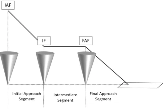
Approach Path
The AP starts at runway threshold and finishes at deceleration point, which delimits the start of deceleration towards approach speed. The AP is formed by three segments: Final Approach Segment (FAS), Intermediate Approach Segment (IS) and Initial Approach Segment (IAS). The FAS is constructed from the runway threshold to the Final Capture Altitude (FCA) or Final Approach Fix (FAF), depending on the type of procedure, while the IS goes from the FAF to the Intermediate Fix (IF). Then, the IAS is cosntructed from the IF to the Initial Approach Fix (IAF), which is the entry point to the procedure as published in the approach chart. The deceleration point is usually located in the middle of the IAS. Aerodynamic configuration points are located at specific characteristic speeds computed by the performance module. FAS construction depends on the type of approach; precision approaches usually impose a slope of approximately -3◦ whilst non-precision approaches are defined by altitude minima. Furthermore, the construction of the AP, specially regarding the IS and the IAS, differs between Continuous Descent Approach (CDA) and classical step-down approaches.
2.2.3
Step-Down versus Continuous Descent Operations
Conventional step-down operations are those where aircraft deceleration is done in a level-off segment usually between the range of 3000 - 5000 feet in order to increase deceleration efficiency, while in CDO profiles, aircraft decelerates along the path as it descends. The comparison of both profiles is observed in Fig. 2.3.
Figure 2.2: Traditional Step-Down Operations (dashed line) compared with CDO (solid line)
2.2. FMS Vertical Profile Computation 12
This is the main goal of CDA function, which is an enabler of CDO. The main advantage of this type of approach is that aircraft descent is continuous and avoids deceleration segments at low altitudes, which has an impact on noise, pollutant gas emissions and, in some cases, fuel consumption [20]. Regarding fuel consumption, large debate has been generated about the fact that CDA sometimes consume more fuel than classic approaches, since idle ratings are higher in a certain flap configuration than in clean configuration. Aircraft deceleration is more efficient in a level-off segment than in CDO, and depending on the arrival procedure could lead to long approach phases as the deceleration is started at high altitudes (e.g. 8000 feet). However, CDO reduce considerably noise emissions.
2.2.4
Theoretical Descent Path
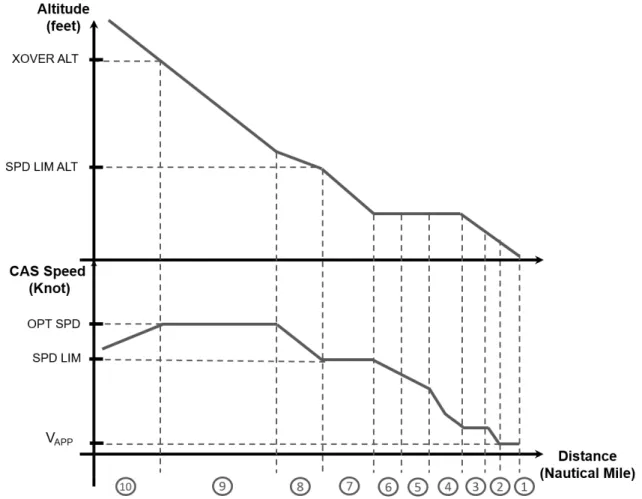
Once the altitude and speed profiles are defined for the approach part, TDP is constructed from deceleration point until cruise altitude, where the Top of Descent (ToD) is located. This path consists of a concatenation of idle and geometric segments, the latter being those generated when an altitude constraint restricts the construction of the [idle] path. In gen-eral, geometric segments require auto-thrust adjustments to maintain a speed target while the elevator guides the aircraft through the vertical path. In contrast, idle segments set auto-thrust to idle while the elevator maintains the target speed. The transition between geometric to idle path is defined by the Geometric Path Point (GPP), which corresponds to the last encountered constrained waypoint. Geometric segments are constructed with a constant (ground) flight path angle. For doing so, a flight path comparison method is used by the FMS to define the type of segment depending on the altitude constraints and aircraft descent capability. In the nominal case, geometric segments require extra thrust to maintain the flight path. Half-airbrakes segments are constructed in case the aircraft needs extra drag to satisfy the altitude constraint. Finally, if half-airbrakes are not sufficient to satisfy that constraint, a vertical discontinuity is created in the flight path, also known as a too steep segment. The optimal descent speed (Mach/CAS) is computed by the FMS depending on the CI value entered by the pilot. This speed is used for the whole descent except when any speed constraint applies. Decelerations from optimal speed to constrained speeds are performed through a defined Energy Share Fac-tor (ESF), a parameter that distributes the available energy (loss) between altitude and speed. The Mach/CAS optimal coupling divides the idle path into two segments; the first one (in the upstream direction) where the aircraft descends at constant optimal CAS until the crossover altitude is attained and the second, where the aircraft flies at optimal Mach speed until the cruise flight level. In order to avoid overshoot, a profile capture segment can be added before intercepting the cruise altitude, which slightly delays the ToD position.
2.2. FMS Vertical Profile Computation 13
Figure 2.3: Typical FMS Vertical Profile
Current vertical profile design is optimized with respect to a selected CI in case that no biases exist between the aircraft behaviour and FMS hypotheses. FMS assumes immediate profile recapture as soon as the aircraft is off-vertical path. However, if the aircraft is devi-ated from its intended lateral path, the vertical path is no longer valid as the computation is based on a lateral trajectory that is not being followed by the aircraft. This is why vertical managed modes (DES mode) cannot be engaged if the aircraft is not in lateral managed mode (Nav mode). Under these circumstances, pilots disregard FMS predictions as they are probably based on hypotheses different than the current condition. The profile is recomputed only in certain conditions, for instance, when a “direct to” action is taken by the pilot (i.e. FMS computes a straight segment to a waypoint assigned by the pilot). However, these recomputed trajectories do not attain aircraft position and pilots are re-sponsible for the proper management of aircraft state in order to reduce the altitude error, a process that may lead to inefficient energy management if the wrong flight strategy is selected.
2.2.5
FMS Predictions and Guidance on the Vertical Plane
Apart from the vertical reference profile, aircraft predicts forwardly its state along flight plan waypoints based on the same state integrators than for the vertical profile
computa-2.2. FMS Vertical Profile Computation 14
tion. Predictions are regularly updated to be consistent with aircraft condition but based on hypotheses that may be different than the aircraft actual behavior. These predictions provide to the pilot a good idea of aircraft intentions but shall be only interpreted as ad-visory information. In scenarios where aircraft is off-lateral path, predictions become less useful since they are based on hypothesis that may differ from the aircraft actual behavior over time.
Regarding the guidance part in descent and approach flight phases, FMS sends pitch and thrust targets to the guidance module, which is in charge of guiding the aircraft through the reference trajectory generated by the FM. However, due to uncertainties such as non-accounted degraded engine performances, unforeseen strong winds and other operational constraints imposed by ATC, aircraft may deviate from that vertical path. In that case, FMS requests a sub-mode engagement to the FG module with the assumption that the profile is recaptured as soon as possible, which depends on the altitude and speed errors with respect to the reference profile. In summary, three logics apply as resumed in Fig. 2.4:
(i) On path: In this scenario the aircraft tends to follow the vertical reference profile (TDP), FMS requests VPATH/SPD sub-mode where the altitude path is followed by the elevator and the speed target is maintained by the auto-thrust. In low altitudes, priority is given to the path rather to the speed. Under these circumstances, aircraft keeps the flight path and, in case of an unexpected tailwind, kinetic energy increases instead of deviating from the profile, which is then compensated by a pilot action.
(ii) Below path: When the aircraft is placed below the reference profile for any reason (usually early descent or head wind gust), the FMS requests VS/SPD sub-mode where the aircraft rejoins the profile with a fixed vertical speed target, while the auto-thrust adjust thrust to maintain the target speed.
(iii) Above path: In this situation, the aircraft tries to rejoin the vertical profile as soon as possible. For doing so, SPD/THR sub-mode is requested by the FMS, where the elevator controls the speed (speed target plus a delta for steeper descent) and the engines are set to idle. Interception of the reference profile is displayed on ND, through a pseudo-waypoint that assumes half-airbrakes extension for a quicker interception.
These modes are only engaged when lateral NAV [managed] mode is engaged. Pilots monitor FMS predictions as they give an idea whether a constraint is going to be missed or satisfied. Additional pilot actions such as airbrakes extension in descent, and flap configuration changes or landing gear deployment in approach may be required in case those sub-modes logics are not sufficient.
2.3. Energy Management 15
Figure 2.4: FMS sub-mode request depending on altitude error
2.3
Energy Management
2.3.1
Definition
In flight operations, the term energy management refers to the continuous exchange that occurs between potential and kinetic energy. According to the law of conservation of energy in physics, energy is neither created nor destroyed but transformed from one form into another. The level of energy of an aircraft is defined through basic parameters such as airspeed, airspeed trend, altitude, drag and thrust [21].
2.3. Energy Management 16
Considering the total energy of the aircraft as the sum of kinetic (Ek) and potential
energy (Ep), chemical energy from fuel can be transformed into mechanical through thrust
whereas aerodynamic drag produces a continuous exchange between mechanical and heat energy, which impacts on the aircraft total energy state. The reservoir analogy proposed by [1] is a good representation of the energy exchanges that take place in an airplane: as observed in Fig. 2.5, throttle levers and drag devices such as airbrakes, flaps and landing gear control the flow of energy, which is then distributed between kinetic and potential reservoirs through the elevator.
2.3.2
High and Low Energy Management in Approach
Pilots ensure that the energy level is appropriate with regards to the flight phase, correcting it if necessary. High-energy occurs when the aircraft is too fast, too high or both, while in low-energy situations the aircraft is below its vertical path or target speed [22]. These situations frequently occur due to wind errors or ATC instructions bringing the aircraft off-path in order to manage the surrounding traffic and may require pilot intervention. In managed modes, different guidance modes are engaged to correct deviations based on aircraft position with respect to the reference profile. On one hand, when aircraft is above path, auto-thrust sets thrust to idle while the elevator keeps a speed target. This mode, called SPD/THR, allows to perform a steep descent and using airbrakes contributes to reduce the vertical deviation. On the other hand, a low vertical speed is maintained by the elevator while auto-thrust keeps the target speed. This mode, called VS/SPD, needs additional thrust to keep the flight path and target speed is usually lowered to be close to the optimal glide speed, defined in Airbus lexicon as greendot, which maximizes the lift-to-drag ratio. In approach phase, good energy management prevents pilots from aborting landing. Pilots have several strategies to correct the energy level of the aircraft and the outcome depends on their skills.
Aircraft state Distance, NM -2.96
Altitude, ft 1000 AGL Speed, kt VAP P
Confaero Full + Landing gear
Table 2.1: Aircraft state at the stabilization point.
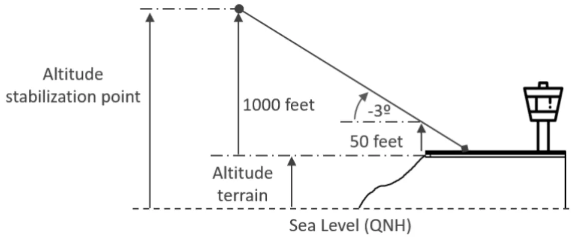
An approach is said to be stabilized if the aircraft is on glide slope flying at final ap-proach speed in landing configuration at a height of 1000 ft Above Ground Level (AGL)
2.4. From FMS Theory to Standard Operating Procedures 17
in Instrument Meteorological Conditions (IMC) or 500 ft in Visual Meteorological Condi-tions (VMC) [23]. This is usually called the stabilization point and is defined as per the parameters defined in table 2.1 and the construction given in Fig. 2.6. Energy misman-agement have a direct impact on flight operation efficiency and sometimes on safety, since unstabilized approaches require to initiate a go-around procedure [24].
Figure 2.6: Typical definition of stabilization point.
Low-energy states are solved by correcting altitude or speed with extra thrust. In high-energy situtations, it is more complex as pilots have the choice of deploying air-brakes, anticipating flaps or extending landing gear to overcome the event. In addition, some of these decisions are irreversible, since flaps or landing gear cannot be retracted except in go-around procedures. That brings pilots to a situation where they have to esti-mate, based on their experience, the best policy that limits the impact on flight efficiency. Airlines are interested in decision aid and automated tools that propose pilots with safe and optimal trajectories, since pilot workload is reduced focusing their attention in tasks such as monitoring and communication.
2.4
From FMS Theory to Standard Operating Procedures
Current Standard Operating Procedures (SOP) rely on FMS to provide position and an effective flight planning to pilots, whose information is displayed either on the EFIS (CDS for A380/A350), consisting of two LCD screens; ND and PFD; or on the MCDU (MFD for A380/A350). MCDU is used for long-term management while EFIS displays information for piloting purposes. The HMI of the system with the pilot is done via the MCDU/MFD.
In an ideal scenario, pilots follow FMS reference profile either manually or automati-cally with the Auto-pilot (AP) and Auto-Thrust engaged [25]. In most operations,
spe-2.4. From FMS Theory to Standard Operating Procedures 18
cially in congested airports, pilots do not usually fly in managed modes but in selected or manually. According to data analysis performed by Airbus customer support teams [21], 99% of aircraft tune a speed target. This technique is usually applied by ATCOs to ensure aircraft separation and assign time gains or delays, as necessary. Radar vectoring is another technique highly applied in dense airports as traffic flows are easily managed and predictability is improved. These radar vectors modify aircraft lateral route with the consequence operational impact for the pilot. Imposed vertical speeds are seldom used by ATCOs but by pilots to monitor easily the rate of descent of the aircraft with respect to their mental calculations. Any ATCO instruction has a direct impact on the optimality of the flown trajectory as it restricts aircraft motion. Nowadays, a common ATC practice is to clear an aircraft for a certain airspace volume, usually bounded by two altitude con-straints. In the worst case, aircraft speed is imposed but it can still optimize the altitude profile. Apart from the above exposed reasons, aircraft leave their vertical trajectory for a set of typical reasons listed hereinafter:
• Clearance Altitude: ATC may not clear an aircraft to descend, i.e. the pilot is not allowed to dial down Flight Control Unit (FCU) altitude to proceed with the descent. Instead, a level-off segment is maintained by the aircraft until ATC provides clearance for a lower altitude. In this scenario, the profile is not recomputed when the ATC clearance is obtained and the aircraft will be usually above the profile.
• Holding pattern: Similar to the previous scenario, ATC may request one aircraft to perform a holding pattern or pilots may request ATC to perform it for some reason (e.g. not prepared for landing). In this case, the aircraft may continue its descent if clearance was already obtained. In most cases, the aircraft will be located above the profile as well.
• Wind error: It stands for a wind that was not forecast and consequently was not entered into FMS wind page for profile construction. Usually, flight plans are computed several hours before departure so that winds may change in this period of time. Wind gusts or turbulences induce aircraft speed to increase or decrease depending on the wind direction (headwind, tailwind, crosswind or vertical gusts). This speed difference with respect to the theoretical descent speed, even if temporary, puts the aircraft above or below the TDP.
• Too Steep Path:This type of segment constructed by the FMS occurs when an altitude constraint cannot be satisfied even with half airbrakes extension hypothesis. The heavier the aircraft, the less descent capability. It results in a discontinuity in the vertical path, which locates the aircraft above path as soon as the constraint is overflown.
2.4. From FMS Theory to Standard Operating Procedures 19
• Other causes: This category can include simplistic models, not accounted perfor-mance degradation due to aircraft aging (engine perforperfor-mance, fuel flow estimation, aerodynamics). Basically, inappropriate fleet management and monitoring may re-sult in non-accounted performance degradation. This causes a discrepancy between FMS models and actual aircraft performance, leading to inaccurate computations. To avoid it, most airlines perform one-to-one optimization for each aircraft of their fleet, which reduces aircraft exploitation costs.
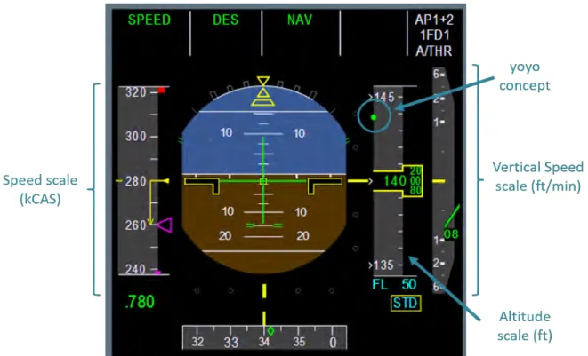
Altitude error is displayed on PFD and MCDU through the vertical deviation label. Figure 2.7 displays vertical deviation “yoyo” concept, a green circle displayed on the alti-tude scale that shows the deviation from the TDP based on the current aircraft altialti-tude. Vertical deviation accurate value is displayed on FMS Progress page. Pilots are aware of aircraft energy state and estimate the best flight strategy to perform a stabilized ap-proach, acting on flight control surfaces consequently. Thus, they are fully responsible for managing the total energy of the aircraft. This study proposes a decision-aid tool that computes the optimal flight strategy for a stabilized approach taking into account the current aircraft energy state. The advantages of this approach are numerous, since it decreases non-stabilized approaches and go-around procedures, flight crews workload during approach at the same time as some criterion is optimized.