HAL Id: hal-01633650
https://hal.archives-ouvertes.fr/hal-01633650
Submitted on 19 Jun 2018HAL is a multi-disciplinary open access archive for the deposit and dissemination of sci-entific research documents, whether they are pub-lished or not. The documents may come from teaching and research institutions in France or abroad, or from public or private research centers.
L’archive ouverte pluridisciplinaire HAL, est destinée au dépôt et à la diffusion de documents scientifiques de niveau recherche, publiés ou non, émanant des établissements d’enseignement et de recherche français ou étrangers, des laboratoires publics ou privés.
Hot Forming Process Analysis of Ti6Al-4V Alloy:
Experiment, Behaviour Modelling and Finite Element
Simulation
Vincent Velay, Hiroaki Matsumoto, Vanessa Vidal, Luc Penazzi, Fabien
Nazaret, Yves Marcel, Maxime Bouillane
To cite this version:
Vincent Velay, Hiroaki Matsumoto, Vanessa Vidal, Luc Penazzi, Fabien Nazaret, et al.. Hot Forming Process Analysis of Ti6Al-4V Alloy: Experiment, Behaviour Modelling and Finite Element Simulation. ICSAM 2015 - 12th International Conference on Superplasticity in Advanced Materials, Sep 2015, Tokyo, Japan. p. 183 - 189, �10.4028/www.scientific.net/MSF.838-839.183�. �hal-01633650�
Hot forming process analysis of Ti6Al-4V alloy: experiment, behaviour
modelling and Finite Element simulation.
V. Velay
1,a ,H. Matsumoto
2,b ,V. Vidal
1,c ,L. Penazzi
1,d ,F. Nazaret
3,e ,Y.
Marcel
4,fand M. Bouillane
5,g1Université de Toulouse; INSA, UPS, Mines Albi, ISAE; ICA (Institut Clément Ader), Albi, France 2Advanced Materials Science Faculty of Engineering, Kagawa University, Japan
3AUROCK, 54 rue Gustave Eiffel, Albi, France
4Methods & Process, PRODEM - BONNANS Group, Cornebarieu, France 5Methods & Process St-Eloi, AIRBUS, Toulouse, France
a [email protected],b[email protected],c[email protected],d [email protected],e[email protected],f[email protected],g
Keywords: Titanium alloy, Behaviour Modelling, Hot Forming, Finite Element Simulation, Micro-structural observations.
Abstract. The present investigation aims at evaluating and understanding the thermo-mechanical
be-haviour of a titanium alloy under hot forming conditions. In this work, several considerations are ad-dressed. First, Scanning Electron Microscopy observations are performed to assess the evolutions of (α− β) phases, grain size, defects regarding the thermo-mechanical loadings from different static and dynamic tests (various temperatures and strain rates). Hence, the relationships between mechanical properties and micro-structure evolutions in such conditions allow a first assessment of the deforma-tion mechanisms in link with the macroscopic stress-strain curves. Afterwards, a behaviour model formulation associated to an identification procedure of the parameters of the constitutive equations is proposed. Finally, several tests performed under hot forming conditions and conducted on an in-dustrial press are compared to Finite Element calculations. Results are compared and provide some interesting improvement ways in order to investigate the influence of the process parameters on the final shape of the part.
Introduction
Ti-6Al-4V alloy is widely used in sheet metal forming processes, complex parts can be formed if favourable conditions are considered (high temperature greater than 900◦C and low strain rates less
than 10−3s−1). In such conditions, a high formability of the material is obtained associated with su-perplasticity mechanisms. However, such conditions (high temperature and very long forming stage) are very binding. Therefore, new forming strategies seem to be interesting to analyse (high strain rates and low temperature levels)[1]. Moreover, grain refinement can be introduced [2, 3], it is recog-nized as a method for revealing the superplasticity at lower temperatures and higher strain rates. The objective of the present investigation is to consider an ultra-fine grained micro-structure of Ti-6Al-4V alloy with an initial α-grain of 3µm. The mechanical behaviour of this typical micro-structure is studied by performing different mechanical tensile tests from a temperature range between 550◦C and
730◦C. The results are analysed by using the stress-strain curves and the induced micro-structural
evo-lutions. Afterwards, a behaviour model using appropriate constitutive equations is presented [4, 5, 6], an identification strategy of the model parameters is discussed [7]. Finally, the behaviour model is implemented in a Finite Element Code in order to simulate the behaviour of a realistic industrial part under hot forming conditions. The results provided by the numerical simulations are compared with the shapes formed with an industrial press.
Experimental Investigation
The section is dedicated to the the mechanical characterization of the Ti-6Al-4V alloy, it includes sev-eral tensile tests and some micro-structural observations. It constitutes a preliminary stage to under-stand the deformation mechanisms which have to be considered in the constitutive laws of a behaviour model.
Material. A plate with a thickness of 3 mm was hot-rolled to provide the Ti-6Al-4V alloy sheets.
The Ti-6Al-4V plate has an equiaxed (α+β) micro-structure with an average α grain size of 3µm. The
α phase ensures excellent properties at low temperature and high strain rate [2] whereas β precipitation
contributes to the accommodation mechanism for stress-concentration at grain boundaries.
Testing. The mechanical tests consider a temperature range between 550◦C and 730◦C and
dif-ferent strain rates from 10−4s−1 to 10−2s−1. Different tensile tests are performed, all the mechanical tests are conducted on servo-hydraulic testing machine. However, in order to perform valid mechan-ical tests from the very small deformations (at the beginning of the test) to the very large ones (till the failure of the specimen), various equipments are required. First, for the small deformation case, an induction furnace specially designed for the flat specimens is considered. It allows an accurate mea-surement of the strain levels by using an extensometer but it is limited to a strain range of 20%. For the large deformation case, another equipment is used, it considers a heat resistive furnace with three heating zones controlled by S-thermocouples ensuring a temperature homogeneity of the sample. It allows to perform tensile tests till the failure of the specimen and the maximal elongation, depending on the test conditions, can be reached. In the case of the small deformation conditions, both strain controlled loadings are performed. On the one hand, a monotonic loading is conducted till a deforma-tion of 10% for different temperatures and different strain rates. On the other hand, the same tensile tests are performed at a strain rate of 10−4s−1 followed by a strain dwell time of 600s. Fig. 1 shows the strain-stress curves obtained at a strain rate of 10−2s−1 and T = {550, 730}◦C and the stress
re-laxation during strain dwell time after a deformation of 10% at a strain rate of 10−4s−1.These results allow an accurate measurement of the evolutions of the elasticity modulus and the yield stress with the temperature . The relaxation curves exhibit a viscous effect very important at these temperature levels. The residual stress measured at the end of the dwell time can be defined as a non viscous stress corresponding to the yield stress and a possible prior hardening. In the case of the large deformation conditions, the strain measurement by the use of an extensometer is not possible due to the very large elongation of the samples. A non linear cross-head displacement is considered in order to obtain a constant strain rate at the center of the specimen. The time variation of the applied displacement u(t) is provided by u(t) = l0(eεt˙ −1) [8, 9] where l0is the initial gauge length, ˙ε is the target strain rate and
t is the time. Afterwards, the true strain εtand the true stress evolution σtare deduced. Fig. 2 illustrates
the strain-stress curves obtained for the very large deformation conditions at T ={550, 730}◦C and
different strain rates. A significant strain rate sensitivity is observed, this phenomenon increases with the temperature. Indeed, a stress range decrease of around 70% is obtained at T = 730◦C and only
25% at T = 550◦C. The maximal elongation increases as the temperature increases and the strain
rate decreases, the values are within the same range order except at T = 730◦C and the strain rate of
10−4s−1 where a very important elongation is noticed (See Fig. 3). Several micro-structural observa-tions are performed. The main objectives are to quantify the (α + β) phase evoluobserva-tions with the test conditions. Both kinds of tests are considered, for the first one (static test), only a heating time were performed, the exposure time to the test temperature can be related to the strain rate level considered in the mechanical test. The second kind (dynamic test) concerns the samples used in the mechanical tests described above. This analysis leads to the following conclusions. First, any phase evolution is observed for the static tests whatever the temperature level and the exposure time to the temperature. Second, the same conclusions can be formulated for the dynamic tests at T ≤ 650◦C. However, a α
0 0.02 0.04 0.06 0.08 0.1 0 100 200 300 400 500 600 700 True strain
True Stress [MPa]
T=550°C; dε/dt=10−2s−1 T=730°C; dε/dt=10−2s−1 0 100 200 300 400 500 600 700 800 900 0 50 100 150 200 250 300 350 400 450 Time [s] Stress [MPa] T=730°C T=650°C T=550°C
Fig. 1: Tensile tests perfomed at T ={550, 730}◦C and a strain rate of 10−2s−1 (left); Stress relax-ation during strain dwell time after a prior strain of 10% and a strain rate of 10−4s−1(right)
True Strain (%)
0 5 10 15 20 25 30 35 40 45 50
True Stress (MPa)
0 100 200 300 400 500 600 700 T=550°C 10-3 s-1 10-4 s-1 10-2 s-1 True Strain (%) 0 50 100 150 200
True Stress (MPa)
0 50 100 150 200 250 300 T=730°C 5.10-4 s-1 10-2 s-1 10-3 s-1 10-4 s-1 5.10-3 s-1
Fig. 2: Strain-Stress curves for the large deformation conditions at T ={550, 730}◦C and different
strain rates 0.0001 0.0005 0.001 0.005 0.01 0 25 50 75 100 125 150 175 200 Strain rate (s−1) Elongationt (%) 550°C 650°C 730°C
10
−2s
−110
−3s
−110
−4s
−1T=730°C
Fig. 3: Maximal elongation evolution with the strain rate at different test temperature (left); tensile test specimens after deformation at T = 730◦C (right)
Behaviour Modelling
This section is devoted to the presentation of the constitutive laws and the use of the experimental results to determine the model parameters.
Constitutive Laws. First, a strain rate partition (Eq. 1) is considered under large deformation
conditions and the elasticity law uses the Jaummann objective rateσσσ of the Cauchy stress (Eq. 1). The▽
constitutive laws includes a von Mises yield criterion f (Eq. 2) to define the elastic domain, an isotropic hardening R (Eq. 2) to describe the monotonic plastic behaviour and viscoplastic flow ˙p to take into
account the strain rate sensitivity of the material at high temperature. Both kind of formulations are expressed, a first one (Eq. 3) in order to describe the high strain rate behaviour (between 10−4s−1 and 10−2s−1) and a more complex one able to consider a wide range of strain rates (Eq. 3). The following equations summarizes the behaviour model:
d dd = ddde+ dddp; σσσ =▽ EEE : (ddd − dddp) (1) f (σσσ, R) = J (σσσ)− R − σ0; R = Q(1− e−bp) (2) d ddp = 3 2p˙ S SS J (σσσ); p =˙ ⟨ f K ⟩n ; p =˙ ⟨ f K1 ⟩n1 + ⟨ f K2 ⟩n2 (3) where J (σσσ) = √ 3
2SSS : SSS and SSS is the deviatoric part of the Cauchy Stress σσσ.
Identification methodology. Several parameters have to be identified, they depend on the
tem-perature. The one-dimensional form of Eq. 1-3 allows the model parameter identification using tensile tests described in the previous section (see Fig.1). Through the elasticity tensorEEE, the Elasticity mod-ulus E can be determined from the tensile tests using the strain measurement performed with the extensometer. The assessment of the elasticity modulus is easy to make at T = {550, 650◦C}, but
more complex at T = 730◦C because of the elasticity limit of the material which becomes very small.
The evolution of the elasticity limits with the temperature can also be determined by the same tests. For each temperature level (T = {550, 650, 730}◦C), the measured values provided by the strain-stress
curves are E ={80200, 70000, 58000}MP a and σ0 ={125, 40, 20}MP a for the elasticity modulus
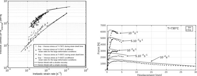
and the yield stress respectively. Depending on the viscosity law considered, Fig. 4-left allows to de-termine the parameters K and n for the first law, and Ki and ni, (i = 1, 2) for the second one. In this
latter case, the stress relaxation are used and a very broad range of strain rates can be reached. The internal stress σinternal is the non-viscous stress and corresponds to the asymptotic stress obtained at
the end of the strain dwell time. Moreover, the values provided by the tensile test performed under large deformation conditions are added to Fig. 4 and allow to consider higher strain rates. Last, the hardening parameters Q and b are also assessed by using the tensile test under small deformation con-ditions. The last stage of the identification process is performed at the scale of the sample [7]. This step requires the implementation of an inverse analysis combined to a FE simulation and an optimisation toolbox. Fig. 4-right illustrates the final results by a comparison of the force-displacement curves at
T = 730◦C and different strain rates provided by FE simulations and experimental tests under large
deformation conditions.
Hot Forming Simulation
The previous behaviour model is implemented in the ABAQUS Finite Element code in order to repro-duce hot forming simulation of an industrial part (countersplice part) as illustrated in Fig. 5. Several forming temperatures are considered (T = {550, 650, 730}◦C). The sheet is compressed between a
matrix and a punch. The simulations are divided into several steps. First, the initial conditions consider a uniform temperature and a constant contact friction during all the simulation. Then, in the step 1, the gravity field (active in all the steps) is applied on the sheet, followed by an imposed displacement of the punch to perform a pre-deformation (step 2). Afterwards, when the contact between the punch, the sheet and the matrix is active, a forming force of 150 kN allows to produce the part (step 3). At the end, both spring back effects are modelled, the first one at the forming temperature (step 4) and the second one at the room temperature (step 5). For each temperature, a punch speed of 0.1 mm/s
10−8 10−6 10−4 10−2 100 100
101 102 103
Inelastic strain rate [s−1]
Viscous Stress (
σ
−
σinternal
) [MPa]
Exp − Viscous stress at T=730°C during strain dwell time Exp − Viscous stress at T=730°C at different strain rates for the large deformation conditions Exp − Viscous stress at T=550°C during strain dwell time Exp − Viscous stress at T=550°C at different strain rates for the large deformation conditions Norton Model with a double viscosity Norton Model with a simple viscosity
Displacement [mm] 0 5 10 15 20 25 30 Force [N] 0 1000 2000 3000 4000 5000 6000 7000 T=730°C 10-4s-1 10-2s-1 5.10-3s-1 10-3s-1 5.10-4s-1 - Sim o Exp
Fig. 4: Evolution of the viscous stress with plastic strain rate (left); Reaction force versus applied displacement for the test performed under large deformation conditions at T = 730◦C, experiment
and Finite Element Simulation (right)
is considered for the forming stage. Fig. 5a illustrates the different parts and the restrained displace-ment assumed for the simulation steps, the matrix and the punch are considered as rigid bodies. Fig. 5b and Fig. 5c describe distance (in mm) from node to surface in contact through the COPEN vari-able at T = 550◦C and T = 730◦C respectively. The results show an important distortion of the
sheet at T = 550◦C compared to the forming temperature of 730◦C. These simulations have to be
compared to experimental forming tests which were performed by PRODEM Company. These anal-ysis are presently investigating, they consist in comparing the final shape of the part with those given by the finite element simulations after spring back at the room temperature. Fig. 6 shows the results performed at T = 550◦C and T = 730◦C. The first observations show a part successfully formed
at T = 730◦C and an important distortion at T = 550◦C as predicted by the numerical simulations
(see Fig. 5b,c). These observations have to be quantified by performing flatness measurements of the deformed sheet. The results will be compared with the simulations.
Maximal distortion: 4.27 mm Maximal distortion: 0.43 mm Punch Restrained displacements Ux=Uy=0 at step 5 x y z Sheet Matrix
Restrained displacements Ux=0 from step 1 to step 4
(c) (b)
(a)
Fig. 5: Modelling of the different parts (Punch, Matrix and Sheet) (a); Spring back effect after step 4 at T = 550◦C (b) and T = 730◦C (c)
Summary
The present investigation aims at evaluating and understanding the formability of Ti-6Al-4V alloy under hot forming conditions (T ={550, 650, 730}◦C. Different tensile tests are performed in order
to evaluate the mechanical behaviour from the small deformations to the very large elongations. They are used to identify constitutive behaviour equations able to take into account several phenomena like the strain rate sensitivity and isotropic hardening when this latter occurs. Last, the behaviour model is introduced in the ABAQUS Finite Element software and hot forming operations of an industrial part
T=730°C T=550°C
Fig. 6: Comparison of the final shape after hot forming operation at T = 550◦C and T = 730◦C
are simulated . The results provide an important distortion of the part formed at T = 550◦C whereas
the shape obtained at T = 730◦C is accurate. This investigation is in progress and the numerical results
will be compared to those obtained by experimental forming tests performed at PRODEM company. The preliminary analysis seems to be in a good agreement with the numerical results.
Acknowledgement
The authors gratefully acknowledge the French Midi Pyrénées Region for its financial support.
References
[1] E-L Odenberger, R. Pederson and M. Oldenburg, Thermo-mechanical material response and hot sheet metal forming of Ti-6242, Mat. Sci. and Eng. A489 (2008) 158-168.
[2] H. Matsumoto, K. Yoshida, S-H. Lee, Y. Ono and A. Chiba, Ti–6Al–4V alloy with an ultrafine-grained microstructure exhibiting low-temperature–high-strain-rate superplasticity , Mat. Let. 98 (2013), 209-212.
[3] H. Matsumoto, V. Velay, A. Chiba, Flow behavior and microstructure in Ti–6Al–4V alloy with an ultrafine-grained α-single phase microstructure during low-temperature-high-strain-rate su-perplasticity, Mat. and Des., Vol.66 B5 (2015) 611-617.
[4] J. Lin and T.A. Dean, Modelling of microstructure evolution in hot forming using unified con-stitutive equations, J. of Mat. Proc. Tech. 167 (2005) 354-362.
[5] J. Lin, Selection of material models for predicting necking in superplastic forming, Int. J. of Plast. 19 (2003) 469-481.
[6] B. H. Cheong, J. Lin and A.A. Ball, Modelling of hardening due to grain growth for a superplastic alloy, J. of Mat. Proc. and Tech. 119 (2001) 361-365.
[7] V. Velay, H. Matsumoto, L. Sasaki and V. Vidal, Investigation of the mechanical behaviour of Ti-6Al-4V alloy under hot forming conditions: Experiment and modelling, Mat. und werk. 45(9) (2014) 847-853.
[8] P. N. Comley, ASTM E2448 - A unified test for determining SPF properties, J. of Mat. Eng. and Perf.: 17 (2008) 183-186.
[9] W. Pan, M. Krohn, S. Leen, T.H. Hyde and S. Walloe, A sigmoidal model for superplastic de-formation, J. of Mat. Des. and Appl. 219 (2005) 149-162.