HAL Id: hal-01709501
https://hal.archives-ouvertes.fr/hal-01709501
Submitted on 25 Apr 2019
HAL is a multi-disciplinary open access
archive for the deposit and dissemination of
sci-entific research documents, whether they are
pub-lished or not. The documents may come from
teaching and research institutions in France or
abroad, or from public or private research centers.
L’archive ouverte pluridisciplinaire HAL, est
destinée au dépôt et à la diffusion de documents
scientifiques de niveau recherche, publiés ou non,
émanant des établissements d’enseignement et de
recherche français ou étrangers, des laboratoires
publics ou privés.
Thermal barrier coatings adherence and spallation:
Interfacial indentation resistance and cyclic oxidation
behaviour under thermal gradient
Julien Sniezewski, Vanessa Vidal, Philippe Lours, Yannick Le Maoult
To cite this version:
Julien Sniezewski, Vanessa Vidal, Philippe Lours, Yannick Le Maoult. Thermal barrier coatings
adherence and spallation: Interfacial indentation resistance and cyclic oxidation behaviour
un-der thermal gradient.
Surface and Coatings Technology, Elsevier, 2009, 204 (6-7), pp.807-811.
Thermal barrier coatings adherence and spallation: Interfacial indentation resistance
and cyclic oxidation behaviour under thermal gradient
Julien Sniezewski
⁎
, Vanessa Vidal, Philippe Lours, Yannick Le Maoult
Université de Toulouse, Mines Albi – Institut Clément Ader, Campus Jarlard, 81013 Albi – France
a b s t r a c t
Keywords: TBC Spallation Thermal gradient Indentation In situinvestigationOne of the most critical damage of Thermal barrier coatings (TBC) results from the spallation of the yttria stabilized zirconia (YSZ) layer. The toughness of the interface between the bond coat (BC) and the top coat (TC), measured using indentation technique, is the main parameter that controls the adherence of the zirconia layer. Cyclic oxidation tests, with and without through thickness thermal gradient, are performed and monitored to investigate spallation mechanisms and overall TBC durability.
1. Introduction
Added to internal cooling system applied to blades, vanes and other parts of gas turbines, TBC can decrease the component service temperature down to more than 150 °C. As a consequence, the turbine inlet temperature can be significantly increased to improve engine efficiency while reducing Nox emission with no impact on components durability[1]. Usually, TBC consists of yttria stabilized zirconia deposited by air plasma spraying or electron beam physical vapour deposition. Prior to applying the TBC, the base material, typically nickel base superalloy, is coated with an alumina forming BC composed of NiAl, (Ni,Pt)Al or MCrAlY
[1,2]. Previous studies[2,3]showed that the oxidation of the bond coat and the complex high thermo-mechanical stresses are the major factors generating the degradation of the TBC. Those stresses result partially from the thermal variation that establishes through the thickness of the multi-materials system. The occurrence of such thermal gradients may specifically provoke spallation and enhance the overall damage of the multi-material[4]. Spallation resistance of the TBC is largely controlled by the fracture toughness of the bond coat/top coat interface, a zone where cracks initiate, propagate and coalesce, leading to the loss of adherence of the TBC.
Several methods have been proposed to measure the interfacial fracture toughness of TBC, including “pull-out techniques”[5], notched coatings in 4-point bending[6,7], and various indentation techniques
[8]. In this paper, focus is placed on a method based on Vickers interfacial indentation to determine the apparent fracture toughness of the interface between the substrate and the TBC. Basically the method consists to determine, for as-processed and isothermally oxidised
specimens, the critical load required to produce the smallest interfacial crack (seeSection 3).
In addition, cyclic oxidation is performed using a dedicated oxidation equipment able to impose a controlled thermal gradient through the specimen thickness[9]. Specifically, the oxidation/spallation testing equipment includes the possibility to monitor in situ, using various optical means such as high resolution, infrared and rapid cameras, the evolution of the material surface while thermally cycled or shocked. 2. Materials and testing conditions
Two types of sample were investigated. Substrates are AM1 and AM3 single crystal Ni-base superalloy disks with respective diameters of 10 and 25 mm and 2 mm thick. Disks are coated with β-(Ni, Pt)Al BC and ZrO2-8 wt.% Y2O3TC deposited by EB-PVD. The thickness of the TC was respectively 175 µm on AM3 substrate (Fig. 1) and 150 µm on AM1 substrate.
Cyclic oxidation tests are performed in laboratory air on coated AM3 substrate subject or not to a thermal gradient. Experiments with thermal gradients are carried out at four BC/TC interface temperatures, namely 1156, 1171, 1181 and 1195 °C. For all tests, the thermal gradient within the ceramic layer is similar, close to 90 °C. Experiments without thermal gradient are performed at 1220, 1200, 1180 and 1160 °C. The typical oxidation cycle characteristics are given inTable 1respectively for tests with and without thermal gradients.
Interfacial indentation measurements are carried out on “as-depos-ited” AM1 un-aged sample and samples oxidised at 1150 °C for different times: 30, 60 and 110 h; in order to evaluate the evolution of toughness as a function of ageing time. For each sample, a series of indentation are performed using various loads. For statistical and reproducibility purposes, a minimum of three indentations is performed for each load.
Using SEM observations, the diagonal of Vickers indent imprints (2b) and the length of the interfacial cracks (2a) produced by the application ⁎ Corresponding author. Ecole des Mines d'Albi Carmaux, Campus Jarlard, 81013 Albi –
France. Tel.: +33 6 67 09 98 30; fax: +33 5 63 49 32 42. E-mail address:Julien.sniezewski@enstimac.fr(J. Sniezewski).
of a load P, are measured (Fig. 2). Then, a mean value of the length crack for each indentation load (P) is calculated.
Note that measured crack length (2a) includes the diagonal of the indent at the interface.
3. Experimental methods
3.1. In situ thermal gradient controlled cyclic oxidation test
During service cycle, the thermal insulation of the TBC generates a temperature gradient through the thickness of the coating. In order to reproduce as close as possible those conditions of materials utilisation, a cyclic oxidation equipment has been designed and implemented. The experimental mean is composed of a sample-holder, a shuttle-furnace, a CCD-camera, a cooling-unit and a control-unit. It is able to impose and adjust the thermal gradient within the investigated specimens thickness during the oxidation phase. This gradient is generated using a specific sample-holder including the circulation of a cooling fluid. The various possible configurations are illustrated inFig. 1. The temperatures of the sample top face, the interface and the sample back face are represented by continuous and dotted line. The versatility of the equipment allows three configurations:
- for a given top face temperature, the value of the thermal gradient can be adjusted,
- for a given interface temperature, the top face and back face tempera-ture can be adjusted,
- for a given magnitude of the thermal gradient, the top face tempera-ture (and consequently the back face temperatempera-ture) can be adjusted. The equipment is entirely automated. This is ensured by the implementation of a computer-aided shuttle-furnace whose motion on top and out of specimen results in the required programmed thermal cycle, including a large range of achievable temperature profiles. Indeed, the experimental mean can reproduce commonly used cycles including a 20 min heating from room temperature to 1100 °C–1150 °C, a 1h high temperature exposure and a 20 min cooling; or perform more specific cycles with higher heating and cooling rates and higher oxidation temperatures.
In situ monitoring of the cooling phases is performed using a camera that detects possible spallation events for each cycle. The focal length of the camera can be changed which allows to view either the whole surface of the specimen or smaller zones to investigate finer details of spallation mechanisms. Images of the camera are directly recorded by a computer and are straightforwardly treated using image analysis software. The mass resolution of the technique (i.e. ∆m) can be calculated considering that the smallest detectable spall accurately corresponds to the size of an elementary pixel of the camera detector.∆m can be written as (Eq.(1)):
Δm = dspecimend focal
! "2
δxδyξoρo ð1Þ
where dspecimen, dfocal, δxand δyare respectively the distance from the camera to the specimen, the focal length of the camera, and the sizes of a pixel. ξoand ρostands for the coating thickness and density. Mass resolution for 200 µm thick TBC is 0.0468 mg.
3.2. Indentation tests
The measurement of the adhesion between substrates and coat-ings has been an area of interest for many years, for instance in “Metal/Thermally Grown Oxide (TGO)” systems[10].
In TBC, typical spallation damages induced by thermo-mechanical stresses, generally locate at the interface between the BC and the TC. As Fig. 1. Various conditions of oxidation with thermal gradient for 175 µm thick EB-PVD TBC sample.
Table 1
Details of the thermal characteristics of the various tests performed. Heating rate Cooling rate Time to stabilisation
Exposure time at oxidation temperature for each cycle With thermal gradient 2 °C ·s− 1 1.6 °C·s−1 12 minutes 48 minutes Without thermal gradient 8.5 °C·s−1 8 °C·s−1 3 minutes 57 minutes
Fig. 2. SEM micrograph showing a typical crack pattern after interface indentation (2a is the length of the crack and 2b the diagonal of the indent).
previously discussed, those in-service failures are related to the loss of adhesion between the BC and the TP which originates from the interfacial TGO and the development of residual stresses in the TBC[11]. The loss of adhesion can be experimentally appreciated by determining the resistance of the interface to initiate and propagate cracks when locally loaded using a Vickers indent applied with various gradually increased forces. The generated cracks, resulting from the application of a critical load, show semi-circular shape. For bi-materials, a simple model basically based on a rule of mixtures to quantitatively measure the apparent toughness of the interface, is proposed in [12]. The methodology relies on the determination of the threshold force or critical load Pcrequired to initiate a crack with a critical size ac. If the applied load is lower than Pc, only the indent resulting from the indentation is observed. If it is higher than Pc, a crack originating from the indent is formed. The length of the crack increases with the applied loads. For very high load, the complete TBC delamination can occur. Then, from the values of Pcand crack length, the apparent interfacial toughness (Kca) is calculated by using the relation:
Kca= 0; 015 Pc a3 = 2c E H ! "1 = 2 i ð2Þ
where Pcis the critical load producing a crack with length ac, E is the Young modulus, H the hardness and i stands for parameters related to the interface.
In our case, where indentation is performed precisely at the BC/TC interface, the hardness and the elastic modulus of both materials are included in the calculation of the ratio (E/H)i:
E H ! "1 = 2 i = E H
# $
1 = 2 S 1 + HS HR % &1 = 2 + E H# $
1 = 2 R 1 + HR HS % &1 = 2 ð3Þwhere subscripts S and R stand respectively for the substrate and the coating. Young modulus and hardness used for the calculation are:
- Ebond coat= 200 GPa[2], - Etop coat=53,3 GPa[14],
- Hbond coat=9.4 GPa (experimental measurement), - Htop coat=3.8 GPa[14].
Note that to transpose the approach developed in [12] for bi-materials to the case of TBC systems, it must be considered that the thickness of the TGO on which the indentation is performed is much lower that the size of the indent imprint. This reasonably allows to neglect the influence of the TGO. In addition, the method does not take into account the possible metallurgical evolution of both the BC and the TBC during high temperature exposure. However, at least in the frame of the approach essentially comparative developed in the paper and as far as the interface is only involved in the mechanical response of the system, the method can be beneficially used to estimate the apparent interfacial toughness.
4. Results and discussion
Cycles to failure of TBC (NR), corresponding to a surface fraction spalled of 50%, are plotted against the interface temperature inFig. 3for both conditions corresponding to tests with and without thermal gradient. Plot shows a non-linear decrease of NRas the oxidation temperature increase. At the highest interface temperature, circa 1200 °C, no significant difference is observed and NRis very similar in both cases (10 cycles). For lower interface temperatures, NRincreases drastically (for instance, from 21 to 83 for an interface temperature of 1160 °C) if a thermal gradient is established through the TBC. Considering that, for a given interface temperature, the higher temperature imposed to the TBC when exposed to the thermal gradient should decrease the lateral compliance of the coating because of an enhanced sintering, this result is somewhat unexpected. However, this can be satisfactorily explained by the differences: i) in the cooling rate, higher for specimens tested without gradient and prone to induce higher stress within the multilayered material[13]and also ii) in the heating rate, lower for specimens tested without gradient and leading to an overall lower exposure time at high temperature.
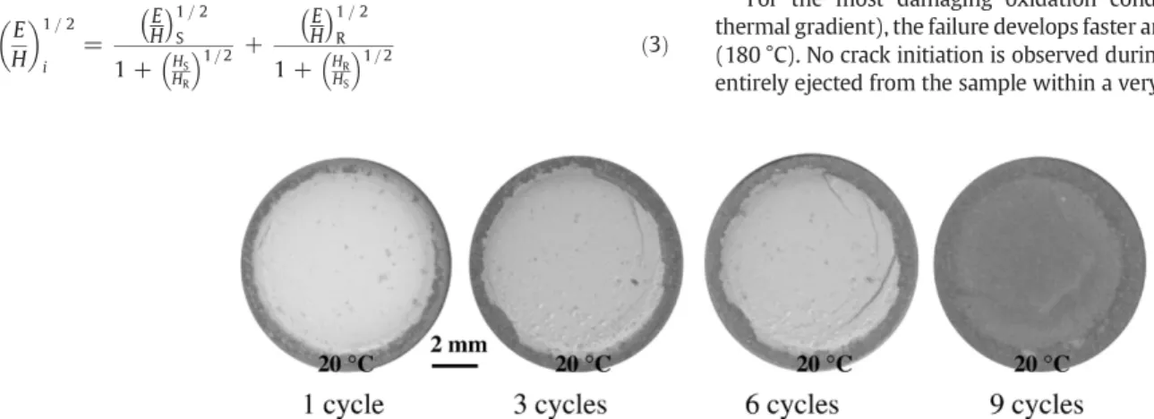
Fig. 4shows the failure morphology of a TBC resulting from successive cycles for a specimen oxidised at 1180 °C without thermal gradient. Failure initiates upon cooling on specimen edges by developing cracks at temperature higher than 200 °C. Cracks subsequently propagate to provoke the complete spallation of the TBC following the ninth cycle.
At lower temperature (100 °C), cracks also initiate at the centre of the sample and small spalled particles are observed into the ceramic thickness. Full spallation occurs very abruptly (less than 0.13 s) at 90 °C where the coating is ejected with high kinetic energy at some centimetres from the sample.
For the most damaging oxidation condition (1220 °C without thermal gradient), the failure develops faster and at higher temperature (180 °C). No crack initiation is observed during cooling and the TBC is entirely ejected from the sample within a very short time. This reveals Fig. 3. Number of cycles to failure as a function of the temperature at the interface
between the bond coat and the top coat.
that the stress level required to provoke spallation is significantly lower. In all cases, coating failure results from crack propagation originated at the BC/TC interface as previously discussed in the literature[4]. SEM observations show that the TGO remains essentially adherent to the TBC but some small parts of alumina are inlayed in the BC. As a result of the increase in alumina thickness during oxidation and associated diffusion processes and growth stress development, the oxide layer damages by the coalescence of voids and the propagation of micro-cracks. This is the main parameter affecting the alumina layer resistance and as a consequence the TBC adherence. The initial thickness of the alumina layer is 1μm and spallation occurs as the thickness reaches 4 to 7μm. The failure morphology of the TBC and its adherence is strongly dependent on the relative toughness values of the various components of the sample. Results indicate that the BC/TC interface is the critical point controlling the TBC resistance.
As presented before, measurement of the interfacial toughness evo-lution on different aged sample is performed using indentation technique.
Fig. 5presents the results of the indentation tests. Plotted in loga-rithmic scales are:
- the evolution of the indent diagonal (b) versus the applied load (P) for all tested specimens. Note that the whole data are used to plot a master curve: the so-called “apparent hardness line” (full line). - the evolution of the length of cracks (a) versus the applied load (P)
for each sample, also fitting single regression lines (dotted lines).
The linear relation between ln(b) and ln(P) shows a slope close to 0.5 which is in good agreement with the general standard formula relating the Vickers hardness (HV) of bulk materials to the ratio between the applied load P and the square of the Vickers imprint diagonal length. The critical load Pcto initiate cracking can be straightforwardly determined. Indeed, Pcis deduced from the intercept between the apparent hardness line Ln(b)–Ln(P) and the Ln(a)–Ln(P) lines.
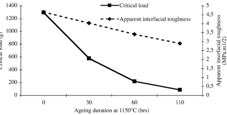
By using Eqs.(2) and (3), the apparent interfacial toughness (Kca) is calculated.Fig. 6represents the evolution of both Pcand Kcaversus the ageing time at 1150 °C.
Pc strongly decreases from the “as-deposited” sample to the
sample oxidised for 30h. This is related to the concomitant increase in oxide thickness, circa 4 µm, revealed by SEM. For longer ageing times, the critical load further decreases according to an exponential relationship. Correlatively, the apparent interfacial toughness also decreases with the ageing time, which can be explained by the morphology change caused by the hot time oxidation. It is important to note that the apparent interfacial toughness of aged TBC is globally lower than the values reported in the literature for bulk TC[15,16]
which can explain satisfactorily why failure preferentially occurs at the interface and not within the ceramic itself.
5. Conclusion
TBC has been characterized using two original techniques. Indentation tests, standing for a simple mean to estimate an apparent interfacial toughness were performed. Shown is that the toughness and thus the resistance to spallation decreases with the exposure time at high temperature in good correlation with the interface degradation caused by oxidation. Cyclic oxidation, with or without through thickness thermal gradient, were performed to investigate the resistance to spallation using a real time approach based on the in situ monitoring of the successive cooling sequences. The number of cycles to spallation drastically decreases as the temperature at the interface between the bond coat and the top coat increases as reported in the literature. Surprisingly, the establishment of a thermal gradient within the TBC does not enhance spallation. This unambiguously shows that the profile of the thermal cycle, i.e. the cooling and heating rate as well as the hot time, both different for the various test, have major effect on promoting TBC spallation. As a consequence, work is in progress to test TBC systems using same heating and cooling rates for specimens oxidised with and without thermal gradient to accurately discriminate the influence of the cha-racteristics of the thermal cycle and the presence of a thermal gradient through the TBC. In addition, it would be very pertinent, in order to relate the static approach developed to estimate the interfacial brittleness to the dynamic cyclic oxidation investigation, to investigate the evolution of the Fig. 5. Principle for the determination of the critical load required to initiate interface
cracking by Vickers indentation.
apparent interfacial toughness for materials, not only isothermally oxidised, but also cyclically oxidised, with and without thermal gradient. References
[1] U. Schulz, C. Leyens, K. Fritscher, M. Peters, B. Saruhan-Brings, O. Lavigne, J.M. Dorvaux, M. Poulain, R. Mévrel, M. Caliez, Aerosp. Sci. Technol. 7 (2003) 73. [2] A.G. Evans, D.R. Mumm, J.W. Hutchinson, G.H. Meier, F.S. Pettit, Prog. Mater. Sci. 46
(2001) 505.
[3] B. Goswami, S.K. Sahay, A.K. Ray, High Temp. Mater. Process. 23 (2004) 2. [4] A.G. Evans, J.W. Hutchinson, Surf. Coat. Technol. 201 (2007) 7905.
[5] S.Q. Guo, D.R. Mumm, A.M. Karlsson, Y. Kagawa, Scr. Mater. 53–9 (2005) 1043.
[6] H.A. Bahr, H. Balke, T. Fett, I. Hofinger, G. Kirchoff, D. Munz, Mater. Sci. Eng. A 362–2 (2003) 2.
[7] P.Y. Thery, Ph. D. Thesis, University Joseph Fourier, Grenoble 2007. [8] J. Yan, T. Leist, M. Bartsch, A.M. Karlsson, Acta Mater. 56–15 (2008) 4080. [9] J. Sniezewski, Y. Le Maoult, P. Lours, Mat. Sci. Forum 595–598 (2008) 1135. [10] Y.H. Qi, P. Bruckel, P. Lours, J. Mater. Sci. Lett. 22 (2003) 371.
[11] H.E. Evans, Int. Mater. Rev. 40 (1995) 1.
[12] D. Chicot, P. Démarécaux, J. Lesage, Thin Solid Films 283 (1996) 151.
[13] V. Teixeira, M. Andritschky, W. Fischer, H.P. Buchkremer, D. Stöver, Surf. Coat. Technol. 120–121 (1999) 103.
[14] S. Guo, Y. Kagawa, Ceram. Int. 32 (2006) 263.
[15] G. Dransmann, R.W. Steinbrech, A. Pajares, F. Guiberteau, A. Dominguez-Rodriguez, A.H. Heuer, J. Am, Ceram. Soc. 77–5 (1994) 1194.