HAL Id: hal-00509416
https://hal-mines-paristech.archives-ouvertes.fr/hal-00509416
Submitted on 12 Aug 2010HAL is a multi-disciplinary open access
archive for the deposit and dissemination of sci-entific research documents, whether they are pub-lished or not. The documents may come from teaching and research institutions in France or abroad, or from public or private research centers.
L’archive ouverte pluridisciplinaire HAL, est destinée au dépôt et à la diffusion de documents scientifiques de niveau recherche, publiés ou non, émanant des établissements d’enseignement et de recherche français ou étrangers, des laboratoires publics ou privés.
Coupled and uncoupled approaches for thin cold rolled
strip buckling prediction
Sami Abdelkhalek, Hamid Zahrouni, Michel Potier-Ferry, Nicolas Legrand,
Pierre Montmitonnet, Pascal Buessler
To cite this version:
Sami Abdelkhalek, Hamid Zahrouni, Michel Potier-Ferry, Nicolas Legrand, Pierre Montmitonnet, et al.. Coupled and uncoupled approaches for thin cold rolled strip buckling prediction. 12th ESAFORM Conference on Material Forming, Apr 2009, Enschede, Netherlands. pp.Pages 833-836, �10.1007/s12289-009-0547-0�. �hal-00509416�
* Corresponding author : Laboratoire de Physique et Mécanique des Matériaux - Ile du Saulcy - 57045 Metz cedex 01
France, Tel : +33 (0)3 87 31 53 82, Fax : +33 (0)3 87 31 53 66, email address : [email protected]
COUPLED AND UNCOUPLED APPROACHES FOR THIN COLD ROLLED
STRIP BUCKLING PREDICTION
S. Abdelkhalek
1,2*, H. Zahrouni
2, M. Potier-Ferry
2, N. Legrand
3, P. Montmitonnet
1, P.
Buessler
31
Ecole des Mines de Paris-ParisTech- CEMEF - UMR CNRS 7635 - BP 207 - 06904
Sophia-Antipolis - Cedex – France.
2
LPMM - UMR CNRS 7554 - ISGMP - Université de Paul Verlaine-Metz - Ile de Saulcy - 57045
Metz - France.
3
ArcelorMittal Research Maizières, R&D Industrial Operations - BP 30320 - Voie Romaine 57283
Maizières Les Metz -Cedex- France.
ABSTRACT: Severe thin strip cold rolling conditions usually induce heterogeneity of in-bite plastic deformation always translated to irregular stress field. This stress field may dwell sufficiently compressive in several out-of-bite areas to cause buckling (flatness defects) which generates stress reorganisation in rolled strip and probably affects the bite zone. Hence, out-of-bite buckling, in-bite elastic-(visco)plastic deformation and thermo-mechanical roll-stack/strip interaction may be strongly coupled. However, a completely coupled model providing realistic rolled strip shape specially when flatness defects occur is not easy to establish. This call for two ways of flatness defect modelling in thin strip rolling: with a completely coupled approach but using a simple buckling criterion, or using an uncoupled approach by chaining strip rolling model calculation with shell element models presenting good buckling computing capabilities. Our objective is the improvement of the flat product rolling – specialized FEM software Lam3/Tec3 [1] using Counhaye simple buckling criterion [3] and Asymptotic Numerical Method (ANM) for shell element model [9,10] respectively with coupled and uncouple approaches detailed in the present paper. These two approaches bring computed stress profiles to very good agreement with experiments and the most important result at this stage is the weak influence of buckling on in-bite stress and strain fields providing a more rigorous justification of the traditional decoupled methods [2,5-8].
KEYWORDS: rolling, finite element method, flatness defect, Buckling, asymptotic numerical method.
1
INTRODUCTION
Due to severe loading in cold rolling, roll stack deformation (flattening, elastic deflection, thermal crown) induces heterogeneous elongation across strip at bite outgoing. This heterogeneity generates residual stress and buckling, named flatness defect in this context. The latter is a major industrial concern in rolling as it is one main factor for quality product.
In addition, buckling implies stress reorganization, because stresses always saturate in buckled areas. This complete rearrangement of the stress field in the post-bite strip can be considered as a change in the boundary conditions of the plastic deformation in the bite. Hence, in-the-bite and out-of-bite stress fields may be strongly coupled.
Thus, mechanical problem includes coupling combining elastic roll stack deformation, strip elastic-(visco) plastic deformation and out of bite buckling. However, most authors [2,5-8] neglect bite/post-bite coupling excepting [3].
2
THIN COLD ROLLED STRIP
BUCKLING PREDICTION
2.1 COUPLED APPROACH
In a previous presentation [4], we introduced in Lam3/Tec3 [1], 3D finite element model adapted for rolling simulation, the Euler-type simple coupled buckling model criterion [3]. Since compressive stress generally saturates around a threshold value when buckling occurs in structure, it consists of an out of bite stress-relaxation algorithm. In fact, it is supposed that buckling will shorten a material element by λ wherever compressive stress exceeds σc. This
decreases the strain sent back after each Newton-Raphson iteration to the constitutive model solver, and therefore the compressive stresses (and as a consequence, the stresses in the tensile area, to maintain mechanical equilibrium). This tends to force iteratively the stress field to respect the buckling criterion (1).
2 2 if ; ( 1, 2) 0 i 3 f i c i i c i c i c σ σ σ σ i k E σ Eh σ δ σ π ì ï ï ï ï ï ï ï -ï ï = ³ = í ï ´ ï ï ï = < ï ï ï ï ï î = (1)
E is Young's modulus, k is a parameter representing the ratio between the material “buckling stiffness” and the Young modulus, h the strip thickness, and δ the wavelength (assumed similar to the compressive stress area dimensions). I and II are the components in the strip
plane deduced respectively from σI and σII. These latter
correspond to principal stresses expressed along the first and the second principal direction I and II which are defined by α angle in the laboratory reference frame. Note that, due to the steady state nature of the model, opposed to the non-steady state character of the waves, only the occurrence of waves can be predicted with a certain degree of certainty, not their severity. Furthermore, although buckling does not occur at element scale, here it is treated locally on each element reaching the critical stress estimated in (1).
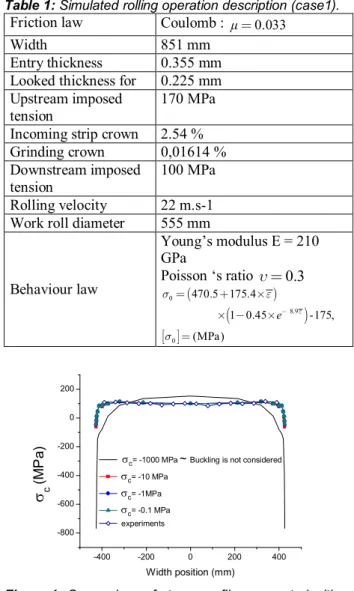
However, despite the simplicity and questionable assumptions of this model, figures 1 and 2 show, for particular rolling conditions (Table 1 : named “case 1”), that :
1. in this case (manifested flatness defect), neglecting the occurrence and effects of buckling results in a completely wrong stress profile;
2. the impact of buckling on the final stress state is to bring it much closer to experiments (measured with tensiometer roll).
3. Furthermore, we note an insignificant dependence of results on the more or less arbitrarily chosenσc
value. This supports the criterion (1) in spite of its approximations.
4. we noted that taking account or not of buckling and its stress relaxation effect doesn’t affect in-bite zone.
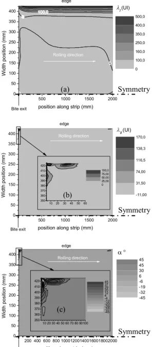
5. manifested flatness defects are identified as shown in figure 3, the wavy edge is visible, I > 0 and
angle α ≈ 0° near the edge (I = x); the significant
II value at the corner of the bite exit might denote
a tendency to have a superimposed oblique wave (α ≈ 30°). However, this simple model is unable to predict neither buckling mode nor post-buckling strip state.
2.2 UNCOUPLED APPROACH
Lam3/Tec3 coupled with a complete shell element buckling model seems certainly more relevant. However, it is very difficult to implement, and the absence of bite/buckling interaction (cf. [4]) justifies uncoupled ("chained") technique described as follows :
§ At first, rolling calculation is made using Lam3/Tec3 without buckling (using a horizontal symmetry plane) providing stress distributions as well as out-of-bite stress field.
§ This stress field is used as residual stress by a code based on asymptotic numerical method (ANM) [9,10] and shell element formulation for buckling plates caused by residual stresses to supply critical load, buckling mode and post-buckling state together with the new (and real) stresses distribution in strip.
Table 1: Simulated rolling operation description (case1).
Friction law Coulomb : =0.033
Width 851 mm
Entry thickness 0.355 mm Looked thickness for 0.225 mm Upstream imposed
tension
170 MPa Incoming strip crown 2.54 % Grinding crown 0,01614 % Downstream imposed
tension
100 MPa Rolling velocity 22 m.s-1 Work roll diameter 555 mm
Behaviour law Young’s modulus E = 210 GPa Poisson ‘s ratiou=0.3 ( ) ( ) [ ] 0 8.9 0 470.5 175.4 1 0.45 -175, (MPa) e e s e s -= + ´ ´ - ´ = -400 -200 0 200 400 -800 -600 -400 -200 0 200 s c (MP a ) Width position (mm)
sc= -1000 MPa~Buckling is not considered
sc= -10 MPa
sc= -1MPa
sc= -0.1 MPa
experiments
Figure 1: Comparison of stress profiles computed with and
without accounting buckling, and measured in experiments (far away enough from the bite).
-20 -15 -10 -5 0 5 10 15 -200 0 200 400 600 800 1000 1200 1400 1600 1800 C o n ta ct p re ss u re ( MP a )
Position along the edge streamline (mm)
With buckling Without buckling
Figure 2: Work roll/Strip contact pressure profile is not
2.2.1 Asymptotic numerical method formulation Considering Hu-Washizu functional, the stationary condition can be written in the following form
(
)
{
[
]
}
( )
1 HW : : : t u v t u e φ δS γ γ D S S δγ δγ dv gP δu -é ù = êë + - úû+ +-ò
% % (2)where D is the elastic stiffness tensor, S is the second Piola Kirchhoff stress tensor, γu is the compatible Green
Lagrange strain obtained from the displacement field and which can be decomposed into a linear and a quadratic part
γu =γl (u) +γnl (u,u). γ% is the enhanced part of the strain
independent of the displacement and assumed to be orthogonal to the stress field. Pe(δu) is the virtual work of
external load and g is a scalar load parameter. The latter gets critical value gc at bifurcation point when buckling
happens. 0 0 100,0 00 0 0 0 100,0 00 0 0 0 100,0 00 0 0 0 100,0 00 0 0 0 100,0 00 0 0 0 100,0 00 0 0 0 100,0 00 0 0 0 100,0 00 0 0 0 100,0 00 0 0 0 100,0 00 0 0 0 100,0 00 0 0 0 100,0 00 0 0 0 100,0 00 0 0 0 100,0 00 0 0 0 100,0 00 0 0 0 100,0 00 0 0 0 100,0 00 0 500 1000 1500 2000 0 50 100 150 200 250 300 350 400 lI(UI) edge Bite exit Rolling direction W id th p o s it io n (m m)
position along strip (mm)
0 100,0 160,0 250,0 350,0 400,0 500,0 500 1000 1500 2000 0 50 100 150 200 250 300 350 400 10 20 30 40 50 60 350 360 370 380 390 400 410 420 0 25,00 50,00 75,00 100,0 Bite exit edge Rolling direction lII(UI) W id th p o s it io n (m m )
position along strip (mm)
-11,00 31,50 74,00 116,5 138,3 170,0 200 400 600 800 100012001400160018002000 0 50 100 150 200 250 300 350 400 10 20 30 40 50 60 70 80 90100 350 360 370 380 390 400 410 420 -45 -37 -29 -20 -12 -4 4 12 20 29 37 45 Bite exit edge Rolling direction W id th p o s it io n (m m )
position along strip (mm)
-45 -32 -19 -6 6 30 45 45 a °
Figure 3: Flatness defect prediction. a : first principal
buckling strainλI, b: second principal buckling strain λII, c : angleα defining the eigendirections of the buckling strain λ .
The basic idea of the ANM consists in searching the solution path of the non-linear problem (2) under an asymptotic expansion form with respect to a control parameter ‘a’. This expansion is developed in the neighbourhood of a known regular solution (U0, 0) as
following:
(
)
2 0 1 2 2 0 1 2 0 1 0 1 ( ) ... ( ) ... , n n n n U a U aU a U a U g a g ag a g a g a u u u g g g = + + + = + + + = - + -(3) Where u U S g æ ö ç ÷ = ç ÷ ç ÷ è ø% and n is the truncation order of series.
Equation (2) can be written in the following simple form:
( , ) ( ) ( , ) 0
R U l =L U +Q U U -gF = (4) where L(.) is a linear operator, Q(. , .) a quadratic one, F the external load vector and R the residual vector. If we substitute (3) in (4) and equating coefficients of the same power of a, the non-linear problem (4) will be transformed into a sequence of linear problems as follows:
order 1:
( )
0 1 1 2 1, 1 1 1 t L U g F u u g = + = (5) order p (1<p<n) :( )
1(
)
0 1 1 1 , , 0 p t p p r p r r p p L U g F Q U U u u g g -= = -+ =å
(6)( )
0 . tL is the tangent operator which depends only on the initial solution.
2.2.2 Applications and results
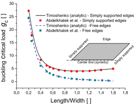
Several buckling academic applications and strip rolling cases had been analysed using ANM shell element model. Therefore, critical load (gc) analytical evolutions with
length/width ratio for free and simply supported edge cases where pure compression is considered (cf. [11]) are reproduced (cf. figure 4). Besides, for “case 1” (presented on table 1) out of bite stress fields become closer to experiments after buckling as mentioned in figure 5. Furthermore, figure 6 illustrates the rolled strip post-buckling state presenting wavy edges and longitudinal stationary waves near the bite exit. Moreover, we deduce correlation between the presented approaches in spite of their large differences.
(a) (b) (c) Symmetry Symmetry Symmetry
0,0 0,2 0,4 0,6 0,8 1,0 1,2 1,4 1,6 1,8 0 5 10 15 20 25 30 Sim ply supp orte d Sim ply supp orte d Edge b u ckl in g c ri ti ca l lo a d g c [ ] Length/Width [ ]
Timoshenko (analytic) - Simply supported edges Abdelkhalek et al. - Simply supported edges Timoshenko (analytic) -Free edges Abdelkhalek et al. - Free edges
Center line (symetry)
Figure 4: Critical load (gc) evolution with length/width ratio
for pure longitudinal compressive stress (-1 MPa) where simply supported and free edges are considered.
-400 -200 0 200 400 -800 -600 -400 -200 0 200
s
xx (MPa ) Width position (mm)LAM3/TEC3-MAN (uncoupled aproach) experiments
LAM3/TEC3 Standard version
Figure 5: Comparison of longitudinal stress profiles
computed with Lam3/Tec3 standard version and the uncoupled approach (Lam3/Tec3-MAN), and measured in experiments (far away enough from the bite).
-600 -400 -200 0 200 -400 -300 -200 -100 0 100 200 300 4 00 500 -4 -2 0 2 4 'def3.txt' 'def2.txt' Bite exit -600 -400 -200 0 200 -400 -300 -200 -100 0 100 200 300 4 00 500 -4 -2 0 2 4 'def3.txt' 'def2.txt' Bite exit -600 -400 -200 0 200 -400 -300 -200 -100 0 100 200 300 4 00 500 -4 -2 0 2 4 'def3.txt' 'def2.txt' Bite exit
Figure 6: Flatness defect of rolled strip for case presented
on table 1: wavy edges and longitudinal stationary waves near to the bite exit.
3
CONCLUSIONS
The flat product rolling – specialized FEM software Lam3/Tec3 has been complemented with a simple buckling model inspired by [3]. The computed stress profiles are therefore in very good agreement with experiments and the most important result at this stage is the weak influence of buckling on in-bite stress and strain fields. This was not expected, as out-of-bite relaxed stresses may be viewed as boundary conditions for the bite; but it provides a more
rigorous justification of the traditional decoupled methods of the literature using shell elements looked more adapted models for buckling. Here, decoupled method is adopted using Asymptotic Numerical Method (ANM) for shell element model which gives excellent buckling computing capability with more realistic results. Thus it looks much more precise and predictive buckling model, in particular allowing modelling of post-buckling.
ACKNOWLEDGEMENT
The authors are grateful to ArcelorMittal for its financial support, and for authorization to publish this work.
REFERENCES
[1] A. Hacquin, P. Montmitonnet and J.P. Guilleraut. A steady state thermo-elastoviscoplastic finite element model of rolling whith coupled thermo-elastic roll deformation. Journal of Materials Processing Technology, Vol. 60, pages. 109-116, 1998.
[2] H. Marchand. Modélisation de la planéité en sortie de laminage des produits plats (Modelling flatness in flat rolling). PhD Thesis, Ecole des Mines de Paris, 2000. [3] C. Counhaye. Modélisation et contrôle industriel de la
géométrie des aciers laminés à froid (modelling and industrial control of the geometry of cold rolled steels). PhD Thesis, Université de Liège, 2000.
[4] S. Abdelkhalek, P. Monmitonnet, N. Legrand, P. Buessler. Manifested flatness predictions in thin strip cold rolling. In 11thESAFORM conference forging and rolling, 2008.
[5] Y. Tosawa. Analysis of three dimensional deformation in strip rolling taken deformation of rolls into consideration. Advanced technology of plasticity, vol. 2, pages. 1151-1160, 1984.
[6] A. Bush, R. Nicholls and J. Tunstall. Stress levels for elastic buckling of rolled strip and plate. Ironmaking and steelmaking, vol. 28, pages 481-484, 2001. [7] F. G. Rammerstorfer, F. D. Fisher, N. Friedl. Buckling
of free infinite strips under residual stress and global tension. Journal of applied mechanics, Vol 68, pages. 399-404, 2001.
[8] F. D. Fisher, F. G. Rammerstorfer, N. Friedl and W. Wisser. Buckling phenomena related to rolling and levelling of sheet metal. International journal of mechanical sciences. Vol. 42, pages. 1887-1910, 2000. [9] H. Zahrouni, B. Cochelin and M. Potier-Ferry. Computing finite rotations of shells by an asymptotic-numerical method. Computer Methods in Applied Mechanics and Engineering, Vol. 175, pages. 71-85, 1999.
[10] E.H. Boutyour, H. Zahrouni, M. Potier-Ferry and M. Boudi « Bifurcation Points and Bifurcated Branches by an Asymptotic Numerical Method and Padé Approximants », International Journal for Numerical Methods in Engineering. Vol. 60, pages. 1987-2012, 2004.
[11] S. P. Timoshenko, J. M. Gere, Theory of elastic stability. Mc Graw Hill Book Company, Inc, New York, Second edition, 1961.