HAL Id: hal-01894281
https://hal.archives-ouvertes.fr/hal-01894281
Submitted on 12 Oct 2018
HAL is a multi-disciplinary open access
archive for the deposit and dissemination of sci-entific research documents, whether they are pub-lished or not. The documents may come from teaching and research institutions in France or abroad, or from public or private research centers.
L’archive ouverte pluridisciplinaire HAL, est destinée au dépôt et à la diffusion de documents scientifiques de niveau recherche, publiés ou non, émanant des établissements d’enseignement et de recherche français ou étrangers, des laboratoires publics ou privés.
Enhancement of Directivity of an OAM Antenna by
Using Fabry-Perot Cavity
W. Wei, K. Mahdjoubi, C. Brousseau, O. Emile, A. Sharaiha
To cite this version:
W. Wei, K. Mahdjoubi, C. Brousseau, O. Emile, A. Sharaiha. Enhancement of Directivity of an OAM Antenna by Using Fabry-Perot Cavity. iet microwaves, Antennas & Propagation, 2017. �hal-01894281�
Enhancement of Directivity of an OAM Antenna by
Using Fabry-Perot Cavity
W. L. Wei1, K. Mahdjoubi1, C. Brousseau1, O. Emile2, A. Sharaiha1
1 Institute of Electronics and Telecommunications of Rennes (IETR), University of Rennes 1, Rennes, France 2 Laser Physics Laboratory (LPL), University of Rennes 1, Rennes, France
kouroch.mahdjoubi@univ-rennes1.fr
Abstract—The circular phased antenna array is a common
way to generate waves bearing Orbital Angular Momentum (OAM) in the radio frequency band, but the directivity of this antenna is relatively low. To overcome this drawback, in this paper, we use a Fabry-Perot cavity to enhance the directivity of an OAM antenna based on a circular phased array of patch antennas. The Fabry-Perot cavity consists of a ground plane, an air cavity and a partially reflecting surface (PRS) made of metallic strips. Simulation results show that the OAM antenna achieves a directivity of 16.2 dB with an enhancement of 9.2 dB in E and H planes.
Index Terms—orbital angular momentum, Fabry-Perot
cavity, circular antenna array, patch antenna.
I. INTRODUCTION
Orbital angular momentum (OAM) has been proposed to improve spectral efficiency [1–4] in radio communications, by creating multiple sub-channels of propagation corresponding to the twisting degree of the electromagnetic wave.
Whereas the phase of a usual plane wave is constant on the wave front, the phase α of OAM waves undergoes a linear variation along the angular coordinate ϕ (roll angle): α = lϕ, where l is an integer called the “topological charge” or the order of the OAM mode.
In the radio frequency band, a circular phased array is a common technique for generating OAM waves [1, 5]. It is generally composed of N antennas, where each one is fed by the same signal with a ±2πl/N phase shift compared to its neighbor. Some practical constructions are proposed in [6–8].
In this paper, we present a method to enhance the directivity of an OAM antenna by using the Fabry-Perot (FP) cavity. A circular phased array of four patch antennas is used to generate waves bearing an OAM mode l = 1. This OAM-wave generator is embedded inside the FP cavity and works at a frequency of 2.5 GHz.
II. MODEL OF FABRY-PEROT CAVITY
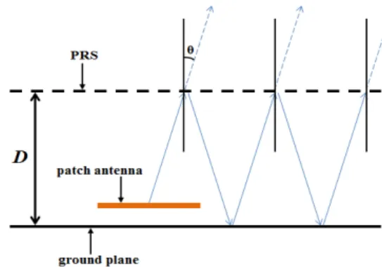
The model of the FP cavity is shown in Fig. 1. It is composed of a ground plane which eliminates the back radiation, a primary source (patch antenna) and a partially reflecting surface (PRS). When the internal wave rays emitted by the primary source arrive at the upper PRS, they are partially reflected back to the cavity and partially transmitted
out. Then, when the reflected rays arrive at the bottom ground plane, they are reflected again towards the cavity. Here we use a PEC ground plane and suppose that the rays are totally reflected at this surface.
To obtain a maximal directivity, the transmitted rays should all be in phase so that they can make a constructive interference. According to [9], the thickness of the FP cavity should meet the following requirement:
( )
(
)
02
1
4
cos
c
D
n
f
β
π
π
θ
=
+
+
(1) where c is the speed of the light in free space, f0 is the workingfrequency, β is the phase of the reflection coefficient of the PRS, n is an integer corresponding to the cavity mode number, θ is the incidence angle of the rays (see Fig. 1).
Fig. 1. Model of the FP cavity with PRS
III. ANTENNA DESIGN A. Phased Patch Array
Here we intend to use a circular phased array of patch antennas to generate the OAM wave [7]. For creating an OAM mode l = 1 with N = 4 antennas, the phase step between each element should be 2πl/N = π/2 radians = 90°.
Fig. 2. Configuration of the OAM antenna
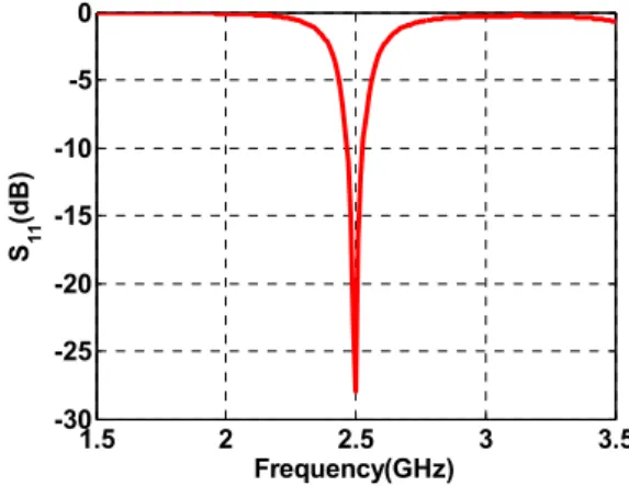
The configuration of the OAM antenna is shown in Fig. 2. The length and width of single patch antenna are 36.5 and 27.4 mm, respectively. The patch array is manufactured on a FR4 substrate with a thickness of 1.6 mm and a relative permittivity of 4.4. All the patch antennas are probe fed using the same signal but with an incremental phase shift between each patch. Fig. 3 presents the reflection coefficient of a single patch antenna, we can see that it is well matched around 2.5 GHz. When the radius of the patch array is 50 mm, the magnitude and phase patterns of the generated wave, observed on a circular area with a radius of 150 mm lying 50 mm above the patch array, are presented in Fig. 4 for the main polarization Ex
(see Fig.2). We can observe that the magnitude at the centre is much smaller than the surroundings and the phase rotates around the centre with a 2π phase shift in one turn. This shows indeed that both the amplitude and the phase of the generated wave correspond to a wave bearing an OAM mode l = 1.
1.5 2 2.5 3 3.5 -30 -25 -20 -15 -10 -5 0 Frequency(GHz) S 11 (d B )
Fig. 3. Reflection coefficient of single patch antenna
Fig. 4. Magnitude and phase patterns of the generated wave for the main polarization Ex
To show the influences of the array radius on the antenna directivity, Fig. 4 presents the E-plane radiation patterns with different array radiuses of 50, 80 and 110 mm. It can be observed that the OAM waves become more directive as the array radius increases, but naturally some side lobes appear. When the array radius keeps increasing, the side lobe becomes even comparable with the main lobe, which means a strong loss of energy. -30 -20 -10 0 10 0° 30° 60° 90° 120° 150° ±180° -150° -120° -90° -60° -30° R=50mm R=80mm R=110mm
Fig. 5. E-plane radiation patterns with different array radiuses B. Phased Patch Array in Fabry-Perot Cavity
It has been demonstrated that the FP cavity is able to enhance the directivity of an antenna [10, 11]. Along this way, we would like to embed the OAM antenna inside the FP cavity to improve its directivity of the main lobe, as shown in Fig. 6. Because the OAM waves are more directive with a bigger array radius, here we choose an array radius of 110 mm.
To realize a good directivity, the wave rays need to be reflected enough times inside the FP cavity, therefore the dimension of the ground plane and the PRS should be large enough. In our design, the ground plane and the PRS both have a dimension of 600 mm × 600 mm. The PRS is made of a set of periodic metallic strips which are manufactured on a FR4 substrate with a thickness of 1.6 mm and a relative permittivity of 4.4. The period and width of the strips are 20 and 4 mm, respectively.
Fig. 6. Configuration of the OAM antenna & FP cavity
According to (1), the cavity thickness depends on the working frequency, the phase of the reflection coefficient of the PRS and the incidence angle of the wave rays. From Fig. 5 we can see that when the array radius is 110 mm, the angle value corresponds to the maximum directivity is at ±15° for the main lobe, so the value of the incidence angle here is 15°. We simulated the PRS alone and found that the magnitude and phase of its reflection coefficient were respectively 0.944 and 0.9π. By substituting these values into (1), we can calculate that the thickness of the FP cavity for the cavity mode n = 0 is equal to 59 mm at a working frequency of 2.5 GHz.
We have varied the cavity thickness to optimize the antenna directivity, the results are shown in Table I. We can observe that the maximum directivity of the OAM antenna changes slightly with the cavity thickness, while the angle value corresponding to the maximum directivity maintains at 11°; the OAM antenna achieves a best directivity of 16.2 dB with a cavity thickness of 58 mm, which is the final value we have used.
TABLE I. MAXIMUM DIRECTIVITY VALUE AND POSITION OF OAM ANTENNA WITH DIFFERENT CAVITY THICKNESSES
Cavity Thickness (mm) Max Directivity (dB) Position (°)
59 14.6 11
58.5 15.7 11
58 16.2 11
57.5 15.5 11
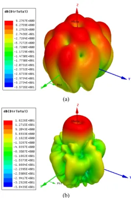
Fig. 7 presents the 3D radiation patterns of the patch antenna array (array radius equals to 110mm) with and without FP cavity. We can observe a null in the center which is one of the characteristics of the OAM waves. In addition, with the use of the FP cavity, the antenna directivity is enhanced and the side lobes are significantly suppressed at the same time.
To give a better view of the influence of the FP cavity on the OAM antenna directivity, we make a comparison of the E-plane radiation patterns in Fig. 8. It can be seen that with the use of the FP cavity, the antenna directivity increases in E-plane, from 7 to 16.2 dB. The maximum directivity is obtained for angle of 11°.
(a)
(b)
Fig. 7. 3D radiation patterns of the OAM antenna (array radius equals to 110mm): (a) without FP cavity; (b) with FP cacity
-20 0 20 0° 30° 60° 90° 120° 150° ±180° -150° -120° -90° -60° -30° without FP cavity with FP cavity
Fig. 8. Comparison of E-plane radiation patterns of the OAM antenna with and without FP cavity (array radius equals to 110mm)
IV. CONCLUSIONS
In this paper, we have presented a method to enhance the directivity of an OAM antenna by embedding it inside a FP cavity. This OAM antenna is based on a 4-element circular phased patch array with an array radius of 110 mm and works at 2.5 GHz. Influences of the FP cavity thickness on the antenna directivity are studied. The OAM antenna finally achieves a directivity of 16.2 dB with an optimized cavity thickness of 58 mm.
ACKNOWLEDGMENT
The authors would like to thank China Scholarship Council (CSC) (No. 201306090101) for scholarship support.
REFERENCES
[1] S.M. Mohammadi, L. Daldorff, J. Bergman, R. Karlsson, B. Thidé, K. Forozesh, T. Carozzi, and B. Isham, “Orbital angular momentum in radio – a system study,” IEEE Trans. Ant. Propag., vol. 58, no. 2, pp. 565–572, 2010.
[2] F. Tamburini, E. Mari, A. Sponselli, B. Thidé, A. Bianchini, and F. Romanato, “Encoding many channels on the same frequency through radio vorticity: first experimental test,” New. J. Phys., vol. 14, pp. 033001, 2012.
[3] J. Wang, J.Y. Yang, N. Ahmed, S. Dolinar, and A.E. Willner, “Terabit free-space data transmission employing orbital angular momentum multiplexing,” Nat. Photon., vol. 6, pp. 488–496, 2012.
[4] Y. Yan, G.D. Xie, N. Ahmed, M. Tur, and A.E. Willner, “High-capacity millimetre-wave communications with orbital angular momentum multiplexing,” Nat. Commun., vol. 5, 4876, 2014.
[5] B. Thidé, H. Then, J. Sjöholm, K. Palmer, J. Bergman, T.D. Carozzi, Ya.N. Istomin, N.H. Ibragimov, and R. Khamitova, “Utilization of
photon orbital angular momentum in the low-frequency radio domain,” Phys. Rev. Lett., vol. 99, pp. 087701, 2007.
[6] Q. Bai, A. Tennant, and B. Allen, “Experimental circular phased array for generating OAM radio beams,” IET Electron. Lett., vol. 50, no. 20, pp. 1414–1415, 2014.
[7] W.L. Wei, K. Mahdjoubi, C. Brousseau, and O. Emile, “Generation of OAM waves with circular phase shifter and array of patch antennas,” IET Electron. Lett., vol. 51, no. 6, pp. 442–443, 2015.
[8] A. Tennant, and B. Allen, “Generation of OAM radio waves using circular time-switched array antenna,” IET Electron. Lett., vol. 48, no. 21, pp. 1365–1366, 2012.
[9] K. Mahdjoubi, T.H. Vu, A.C. Tarot, and S. Collardey, “An overview on the design and properties of EBG antennas,” the 4th European Conf. on Antennas and Propagation (EuCAP 2010), Barcelona, Spain, pp. 1–3, April 2010.
[10] T. Akalin, J. Danglot, O. Vanbésien, and D. Lippens, “A highly directive dipole antenna embedded in a Fabry–Perot type cavity,” IEEE Microw. Wireless Compon. Lett., vol. 12, no. 2, pp. 48–50, 2002. [11] H. Boutayeb, K. Mahdjoubi, A.C. Tarot, and T. A. Denidni, “Directivity
of an antenna embedded inside a Fabry-Perot cavity: Analysis and Design,” Microw. Opt. Technol. Lett., vol. 48, no. 1, pp. 12–17, 2006.