HAL Id: tel-01228853
https://pastel.archives-ouvertes.fr/tel-01228853
Submitted on 13 Nov 2015
HAL is a multi-disciplinary open access
archive for the deposit and dissemination of sci-entific research documents, whether they are
pub-L’archive ouverte pluridisciplinaire HAL, est destinée au dépôt et à la diffusion de documents scientifiques de niveau recherche, publiés ou non,
Tobias Pössinger
To cite this version:
Tobias Pössinger. PhD THESIS Experimental Characterization, Modeling and Simulation of Magneto-Rheological Elastomers. Engineering Sciences [physics]. Ecole Polytechnique, 2015. English. �tel-01228853�
PhD THESIS
OFECOLE POLYTECHNIQUE
Submitted by:
Tobias PöSSINGER
in Partial Fulfillment of the Requirements for the Degree of DOCTOR OF PHILOSOPHY
SPECIALTY: Mechanics
Experimental Characterization,
Modeling and Simulation of
Magneto-Rheological Elastomers
Prepared at the
Sensorial and Ambient Interfaces Laboratory, CEA LIST,
and at the
Solid Mechanics Laboratory, LMS
Mr. Krishnaswamy RAVI-CHANDAR
Professor University of Texas at Austin Rapporteur Mr. Jean-Claude MICHEL Research Director
LMA, Marseille Rapporteur
Mr. Habibou MAITOURNAM
Professor ENSTA Paristech, Palaiseau Head of the Commitee Mr. Pedro PONTE CASTAñEDA Professor University of Pennsylvania Examiner Mr. Olivier HUBERT
Professor LMT, Cachan Examiner
Ms. Laurence BODELOT Assistant Professor Ecole Polytechnique, Palaiseau Examiner Mr. Nicolas TRIANTAFYLLIDIS Research Director LMS, Palaiseau Advisor Mr. Christian BOLZMACHER Research Engineer
CEA LIST Co-Advisor
Mr. Kostantinos DANAS
Research Scientist
Abstract
In this thesis, we study a class of active materials named Magneto-Rheological Elas-tomers (MREs) with a main focus on their coupled magneto-mechanical response up to large strains and up to high magnetic fields. With the purpose of achieving a coupled characterization of MREs behavior for the design of haptic interface devices, this work encompasses experimental, theoretical and numerical developments. The first part of this work is dedicated to aspects pertaining to sample fabrication. Isotropic and magnetic field-cured MREs, composed of soft silicone rubber and mi-crometric carbonyl iron powder, are manufactured using a reliable and repeatable process. A special sample geometry is designed in order to obtain both homogeneous mechanical and magnetic fields during the coupled-field characterization. The inter-facial adhesion between the iron fillers and the silicone matrix in MREs submitted to large deformations is investigated and a critical strain threshold is identified beyond which a primer treatment of the particles is needed to prevent debonding between the particles and the matrix.
The second part of this thesis focuses on the coupled magneto-mechanical charac-terization of MREs and involves both theoretical and experimental developments. Based on the general theoretical framework for transversely isotropic magneto-elastic continua proposed by Kankanala, Danas and Triantafyllidis [Kan04, Dan12, Dan14], the coupled magneto-mechanical constitutive laws for both isotropic and anisotropic MREs are used to determine experimentally the corresponding constitutive model’s material parameters. The actual characterization of MREs is conducted thanks to a specially designed and novel experimental setup allowing tensile tests up to large strains and under high magnetic fields. The experimental data thus obtained pro-vide the constitutive models for the isotropic and anisotropic MREs needed as input for the subsequent numerical simulations.
The third part of this work pertains to the experiments, modeling and numerical calculations for boundary value problems corresponding to the design of a haptic interface prototype. A coupled variational formulation for a non-uniform applied magnetic field, using displacement, magnetic vector potential and magnetization as independent variables, is proposed and subsequently applied to the solution of the boundary value problem of an MRE layer subjected to the spatially localized mag-netic field produced by an electromagmag-netic coil. The axisymmetric problem is solved numerically using finite element analysis. The device has been built and experimen-tal results are compared to numerical simulations, thus providing a benchmark for the validation of the axisymmetric simulations as well as a proof of concept for the design of haptic interface applications.
Acknowledgment
I would like to express my deep sense of gratitude to my supervisors at the LMS: Professor Nicolas Triantafyllidis, who indicated the right directions and helped me with his immense theoretical background in this for me new field of continuum mechanics. Professor Laurence Bodelot, who always was there for any questions with her accurate help and guidance during the three years of my doctoral thesis. It was a great pleasure to develop together all the experimental facility from scratch. Professor Kostas Danas, who introduced and guided me through the formulation of the FEM methodology and who was there with his exceptional knowledge on MREs if I had questions. I would also like to mention and thank Professor Patrick Le Tallec, head of the lab, who always showed an honest interest on the work of all the PhD students at the LMS.
In the same way, I would like to express my deep sense of gratitude to my supervisors at the CEA LISA: Dr. Christian Bolzmacher, who always supported me during this work with his great knowledge on smart materials and to keep in mind the technological application of MREs. I am especially indebted to the head of the lab (CEA LISA) and director of research at the CEA, Dr. Moustapha Hafez, for the generous funding I received, which was fundamental for my PhD studies.
I would also like to mention the very interesting weekly seminars at the LMS, the excellent courses at the Ecole Polytechnique and the well organized on-site assistance and courses of the doctoral school EDX and thank the people responsible therefore. Next, I would like to thank all engineers and technicians, who generously offered their great expertise and technical support: the mechatronic engineers Vincent De Greef, especially, and Jean-Christophe Eytard at the LMS, Laurent Eck at the CEA. The technicians from the machine shop François Lelong and Antoine Soler, the designing engineer Erik Guimbretiere and the research engineers and specialists in Scanning Electron Microscopy Alexandre Tanguy and Eva Héripré at the LMS. The research engineer and specialist in 3D printing Gwenaël Changeon at the CEA.
I would also like to thank the doctoral students and employees at the LMS and the CEA LISA for the helpful and friendly working atmosphere at both labora-tories. Particular thanks to Annick Latare and Alexandra Joly for their help on administration procedures, as well as to René, Harald, Hakim and the LMS soccer team.
I am very thankful to Professor Krishnaswamy Ravi-Chandar and research director Jean-Claude Michel that they generously took the time to report on my work, to Professor Habibou Maitournam chairing as well as to Professor Pedro Ponte Cas-tañeda and Professor Olivier Hubert completing an exceptional PhD committee.
Contents
Abstract i
Acknowledgment iii
1 Introduction 1
1.1 MREs among smart materials . . . 2
1.2 Classification within MREs . . . 3
1.3 Main MRE research topics and applications . . . 5
1.4 Physical phenomena in MRE behavior . . . 7
1.4.1 Mechanical behavior of MREs as particle-filled composites . . 7
1.4.2 Magnetic response of MREs . . . 10
1.4.3 Magnetic field-dependent modulus . . . 12
1.4.4 Deformation under magnetic field . . . 13
1.5 Approaches to the modeling of MREs . . . 19
1.5.1 Micro-mechanically based modeling of MREs . . . 19
1.5.2 Phenomenological continuum description . . . 19
1.6 Previous experimental characterizations of magneto-elastic properties at finite strain . . . 20
1.6.1 Overview of experimental studies on MREs . . . 21
1.6.2 Magneto-mechanical experimental characterization using con-tinuum models . . . 23
1.7 Scope and organization of the present work . . . 25
2 Materials and samples 27 2.1 Introduction . . . 27
2.2 Sample shape for coupled magneto-mechanical testing . . . 29
2.3 Materials and fabrication procedure . . . 34
2.3.1 Materials selection . . . 34
2.3.2 Fabrication procedure . . . 35
2.4.2 Scanning electron microscopy . . . 41
2.4.3 Macroscopic mechanical tests . . . 45
2.4.4 Discussion of results . . . 47
2.5 Conclusion . . . 50
3 Magneto-mechanical characterization 51 3.1 General theoretical framework . . . 51
3.1.1 Governing equations . . . 52
3.1.2 Free energy function for transversely isotropic MREs . . . 56
3.2 Constitutive parameter identification . . . 58
3.2.1 Reduced form of the free energy function . . . 58
3.2.2 Free energy density and response functions . . . 61
3.2.3 Different test cases . . . 62
3.3 Magneto-mechanical characterization setup . . . 66
3.3.1 Electromagnet . . . 66
3.3.2 Tension system . . . 68
3.3.3 Mechanical diagnostics . . . 70
3.3.4 Magnetic measurements . . . 73
3.4 Experiments and parameter identification . . . 76
3.4.1 Testing protocol . . . 77
3.4.2 Experimental results . . . 78
3.4.3 Parameter identification results . . . 90
3.5 Conclusion . . . 98
4 Numerical implementation 99 4.1 Introduction . . . 99
4.2 Total Lagrangian variational formulation of the fully-coupled magneto-mechanical problem . . . 100
4.2.1 General framework for a non-uniform applied magnetic load . 100 4.2.2 Framework for the prototype device simulation . . . 106
4.3 Axisymmetric FEM formulation . . . 108
4.3.1 Discretized variational principle . . . 110
4.3.2 Axisymmetric space . . . 112
4.4 Problem geometry/mesh, initial/boundary conditions and material
parameters . . . 121
4.5 Simulation results . . . 124
4.6 Experimental validation . . . 128
4.6.1 Haptic surface prototype . . . 128
4.6.2 Experiments . . . 130
4.7 Conclusion . . . 133
5 Conclusion and future work 135 5.1 Conclusion . . . 135
5.2 Future work . . . 137
A Appendix 141 A.1 Derivation of the traction response . . . 141
A.2 Coefficients of the force vector and the stiffness matrix . . . 144
Chapter 1
Introduction
Magneto-rheological elastomers (MREs) are smart materials composed of an elas-tomeric matrix filled with magnetic particles. The viscoelastic characteristics of the matrix combined with the magnetic properties of the particles allow these flexible composites to deform in response to a relatively low externally applied magnetic field. The rapid response, the high level of deformations and the possibility to con-trol these deformations by adjusting the field make these materials of special interest in modern engineering [Bus07]. Due to their unique properties, a variety of tech-nological applications in smart structures based on MREs can be envisioned: novel actuators, smart sensors, artificial muscles, sound control, shape control, product health or lifetime monitoring, etc. (see the review by [Har06]). Yet, no full charac-terization of the magneto-mechanical properties for finite strains and high magnetic fields has been undertaken so far, thus limiting the efficient design of such MRE-based devices.
In this chapter, after introducing MREs and where they stand among smart ma-terials in Section 1.1, a sorting in the class of MRE is proposed in Section 1.2 and the main research topics, as well as some examples of applications, are presented in Section 1.3. Next, physical phenomena involved in the behavior of MREs are discussed in more detail in Section 1.4, from general aspects of the behavior of filled composites to the behavior of MREs under magnetic field. Then we briefly review the different modeling approaches in Section 1.5, as one can find either microscopic-based models or phenomenological continuum descriptions. The latter approach is the theoretical basis for the developments done in this thesis and requires a careful experimental characterization of magneto-elastic material properties. Thus, we also analyze what has been done previously experimentally on this topic in Section 1.6. Finally, the scope of the present work is presented and the organization of the manuscript is detailed to guide the reader through the following chapters in Section 1.7.
1.1 MREs among smart materials
Different stimuli cause some materials called “smart”, “intelligent” or “active” to respond to their environment in a reversible manner, thus producing a useful effect. Common materials that formally have the label of being smart include piezo-electric materials, electro-strictive materials, magneto-strictive materials, electro-rheological materials, magneto-rheological materials, thermo-responsive materials and shape memory alloys. The applied driving forces for field-driven smart materials then can be broadly identified as mechanical fields, electrical fields, magnetic fields and thermal fields. Therefore, an important feature related to smart materials is that they encompass almost all fields of science and engineering.
While electro-active materials usually require high voltages for activation, econom-ically generated magnetic fields (permanent magnets, solenoids) can be used to stimulate magneto-active materials. As a branch of this kind of active materials, electro- and magneto-rheological materials consist of an insulating or non-magnetic matrix (either a fluid, a foam or an elastomer) into which electrically or magnetically polarizable particles are mixed, respectively [Har06].
The first explored [Rab48] and most common magneto-rheological (MR) materials have a fluid matrix. In these MR fluids, the interaction between dipoles, induced by an external magnetic field, causes the particles to form columnar structures par-allel to the uni-axially applied field. As the external magnetic field increases, the mechanical energy needed to yield these chain-like structures increases since it be-comes more and more difficult for the fluid to flow through these formed structures. The obtained field-dependent yield stress, which can be rapidly and reversibly con-trolled, has been exploited in a variety of vibration control or torque transfer devices [Car01, Ber12]. However, the drawback of MR fluids is the settling of their particles and the fact that the devices need to be enclosed. As a solution to this, magneto-rheological foams have been developed, in which the controllable fluid is contained in an absorbent porous matrix. Fluids in these smart devices are thus more resis-tant to gravitational settling. Additionally, no seals or bearings are required and a smaller quantity of fluid is needed [Car00].
A definite answer to the particles settling was the use of an elastomer as the ma-trix. The magnetic particles are mixed into the fluid-like polymer blend but remain locked in place within the cross-linked network of the cured elastomer. Hence, these composite materials are often considered as the solid analogs of magneto-rheological
1.2 Classification within MREs
fluids. The first researchers who conducted preliminary tests on these so-called magneto-rheological elastomers1 are Rigbi and Jilken [Rig83]. They studied the
be-havior of a ferrite elastomer composite under the combined influence of changing elastic stresses and magnetic fields and described the previously unknown magneto-mechanical effects2.
1.2 Classification within MREs
If magnetic fields are applied to the elastomer composite during processing, spe-cial anisotropic properties can be imparted to these materials. They are then called field-structured MREs and it has been observed that they are anisotropic in terms of mechanical, magnetic, electrical, and thermal properties [Car00]. More particularly, an applied uni-axial magnetic field produces chain-like particle structures3: at low
particle concentrations the particles initially form chains that slowly coalesce into columns, as shown in Figure 1.1, while at high concentrations the morphology be-comes slightly more complex, with possible branching between columns and a slight loss in anisotropy [Mar98, Boc12]. A bi-axial (e.g. rotating) field produces sheet-like particle structures [Mar00]. Finally, with the generation of triaxial magnetic fields during processing, a variety of isotropic and anisotropic particle structures can be created [Mar04].
MREs can be further classified according to their main constituents, i.e. the non-magnetic matrix and the non-magnetic filler particles as well as their inherent properties. They usually are composed of a solid, electrically insulating4 matrix, such as silicone
rubber, natural rubber, polyurethane or thermoplastic elastomers [Kal05, Hu05, Che07, Wei10, Kal11]. In fact, a great variety of matrix materials covering a wide range of properties in modulus, tensile strength or viscosity can be found on the market and in the literature. Within all these materials however, MREs based
1They are also often named magneto-active elastomers [Bus10] or magneto-sensitive elastomers
[Kar13]. Respecting the rule of anteriority, we will use magneto-rheological elastomers (MREs) as defined by Carlson and Jolly [Car00].
2The reader interested in a historical overview is referred to the thesis of Schubert [Schu14], who
presented a thorough summary in graphical form.
3In the following, MREs structured by an externally applied, uni-axial magnetic field are termed
field-structured, aligned or transversely isotropic whereas (isotropic) MREs designate com-posites with a random distribution of particles since no structuring field is applied during fabrication in this case.
4We will neither consider conductive or graphite-particle-doped MR elastomers nor the
phe-nomenon of magneto-electrical resistance within the scope of this thesis. The interested reader is referred to the papers of Bica [Bic11] and Ausanio et al. [Aus14], for example.
Figure 1.1: Scanning electron micrograph of a field-structured MRE with low
par-ticle concentration. The parpar-ticles appear as white dots aligned by the externally applied magnetic field in the elastomeric matrix appearing as the black back-ground.
on silicone rubber enjoy much popularity due to their excellent processability, to the good compromise between mechanical, thermal and aging properties, as well as to their widespread use in industrial applications. Furthermore, relatively soft matrices with low elastic moduli are achievable in silicon rubbers and tend to ease the magneto-mechanical interaction [Kal05, Gon07, Dig10, Schu14]. Let’s note also that the individual class of “soft magneto-rheological elastomers” has been claimed, which covers MREs whose matrix is elastically soft. This class includes magnetic gels consisting of magnetic particles dispersed in a gel-like polymeric matrix. Gel materials (fluid within a three-dimensional weakly cross-linked network) can indeed be much softer than classical elastomers. However, they usually have a wet and sticky consistency, and when agitated, these materials start to flow (thixotropy), thereby resulting in poor mechanical properties [Zri97, Rai08, Zub12].
Different types of magnetic filler particles have been used in MREs: magneto-strictive or magnetic shape memory particles, as well as hard or soft magnetic par-ticles. A number of researchers employed highly magneto-strictive particles, usually Terfenol-D [Due00]. This alloy of rare earth crystals is the most effective but a cost intensive magneto-strictive material, capable of showing reversible strains in the order of 10−3 in response to an applied magnetic field [Guy94]. Particles with
1.3 Main MRE research topics and applications
magnetic shape memory have also been used [Sche07] yielding both temperature and magnetic field-driven MRE composites. The dispersion of hard magnetic parti-cles in an elastomeric matrix, magnetized during fabrication, produces anisotropic, magnetically-poled MREs similar to a flexible permanent magnet [Koo12]. However, the most commonly used particles are made of soft ferromagnetic materials such as nickel, cobalt or iron and their alloys [Aus11, Ant11]. In particular, carbonyl iron powder (CIP) with spherical particles has been widely preferred in MREs fabrication [Kal05, Boes07, Dig10, Schu14]. Iron has indeed a high magnetic susceptibility and saturation magnetization, providing high inter-particle interaction forces, as well as a low remanent magnetization required in order to obtain quick and reversible con-trol by the magnetic field in MRE applications. The size of the magnetic particles further distinguishes MREs from ferro-elastomers or ferro-gels5. Standard
ferro-gels (as well as ferro-fluids) tend to include nano-sized particles which are magnetic mono-domains. They agglomerate easily and cannot be separated again once they have agglomerated. Following the definition in the review by Carlson and Jolly [Car00], MREs rather embed micron-sized particles possessing a high number of magnetic domains that, overall, are harder to magnetize [Car00, Mar06].
1.3 Main MRE research topics and applications
Considering the large amount of possible matrix-filler combinations in the litera-ture, many of the early experiments but also current research have been dedicated to the composition and processing of MREs together with the investigation of the ob-tained microstructures by optical microscopy [Far04a], scanning electron microscopy [Gon05, Chen07] or X-ray microtomography [Bor12]. The processing conditions and (field-)curing mechanisms are crucial parameters for the manufacturing in a labora-tory environment. More specifically, the mixed viscosity – a measure of the thickness of the blended composite constituents –, the temperature and the magnetic field will determine the competition between gravitational settling and the alignment of the particles during curing [Als07, Gue12]. The final structure of the MRE is therefore specific to each of these parameters, which complicates the comparison of experi-mental results in the literature.
Furthermore, extensive studies have been conducted to investigate the dynamic small strain behavior of MREs, especially the influence of an external magnetic
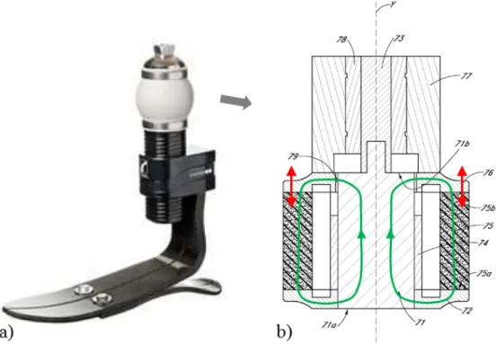
field on mechanical properties such as storage, loss and viscoelastic moduli [Shi95, Jol96, Gin00, Lok04, Kal05, Fan11, Kar13]. Since MREs have been shown to alter their dynamic moduli in response to the field, their performance as tunable vibra-tion absorbers and tunable stiffness devices has been widely studied and prototype applications have been developed [Eli02, Far04b, Cri09, Mar13, Kim14], such as a prosthetic foot [Tho13] shown in Figure 1.2.
Figure 1.2: a) Picture of a smart prosthetic foot device and b) cross-section of the
integrated tunable MRE spring [Tho13]. The motion (red arrows) resistance of the MRE spring (75) can be adjusted by the magnetic flux (green circuit) generated by the coil (74).
In parallel, a large body of research has been devoted to the investigation of the deformation of MRE materials exposed to a magnetic field. The attraction of mag-netically soft and mechanically flexible MREs by magnetic field gradients has been discovered early [Zri96] and the use of this effect in smart high-strain actuators has been proposed [Boes12, Bro12]. Figure 1.3 shows the example of an MRE device en-abling flow control [Ste13]. The deformations induced by a uniform magnetic field have also been studied early [Gin02] but the results are still rather contradictory up to now and cannot yet be explained clearly. We will come back to these aspects in the next section.
mod-1.4 Physical phenomena in MRE behavior
Figure 1.3: Schematic of a smart fluid valve [Ste13]. The flow (large arrows) of the
medium inside a channel (5) can be adjusted by attracting (6) the MRE material (2) by means of an electromagnet (3,4) or a permanent magnet (7).
eling of these materials. The approaches therein can basically be partitioned in micro-mechanical or structural models on the one hand and continuum or phe-nomenological models on the other hand. In the continuum approach that is the theoretical basis for what has been done in this thesis, the material constitutive behavior needs to be characterized with the help of magneto-mechanical experi-ments. In Section 1.6, a review on the available experimental data will show that the magneto-elastic coupled behavior up to high strain and high magnetic fields has not been well explored yet. Hence the design of smart devices capable of high defor-mations has been limited so far and very few applications allow the MRE material to deform up to 20 percent [Cri09, Tho13, Ste13].
1.4 Physical phenomena in MRE behavior
In this section, selected physical phenomena involved in MREs behavior are dis-cussed in more detail, mainly from an experimental point of view. To remain within the scope of this work, the focus is especially set on the quasi-static or low-frequency behavior of these materials while accounting for large strains and high magnetic fields.
1.4.1 Mechanical behavior of MREs as particle-filled composites
Some purely mechanical phenomena characteristic of particle-filled composites have to be clarified when investigating MREs, even before considering magneto-mechanical
aspects. It is well known that the highly nonlinear macroscopic behavior of filled polymers in response to a mechanical load is affected by matrix-filler and filler-filler interactions. Different phenomena have been experimentally observed6 and can be
linked to changes in the microstructure.
Figure 1.4: Illustration of the Mullins effect for a carbon black filled rubber
(par-ticle volume fraction Φvol ∼ 0.2) from [Mie00, Dor04]. Two virgin samples are
either uni-axially stretched directly up to high strain (dashed line) or cycled by increasing the strain amplitude after each set of cycles (solid lines). The stable upload curve for the set of cycles of lowest strain amplitude is highlighted in red. Under large deformations, a softening (characterized by a lower resulting stress for the same applied strain) and a permanent deformation between first and subsequent load cycles can be observed in filled rubbers and MREs. This phenomenon depends on the maximum strain applied and is called “Mullins effect” [Mul57, Mie00, Dor04, Coq06a, Dia09]. It is illustrated in Figure 1.4. The highest softening occurs after the first load cycle and leads to a stable response after few cycles (c.f. Figure 1.4, stable upload curve in red), aside from a smaller fatigue effect [Schu14]. The propensity of the Mullins effect, as well as the composite stiffness are increased with a higher
6The large strain constitutive behavior is described by stress-strain curves: usually, the applied
force f divided by the initial cross-section A0 is plotted versus the measured stretch λ or
engineering strain e = λ − 1. Since this response can be highly nonlinear, different stiffness measures are introduced in the literature. The static or elastic modulus is defined as the ratio of the stress and the corresponding strain, whereas the differential or tangent modulus is defined as the slope of the curve at the considered point.
1.4 Physical phenomena in MRE behavior
filler content (see Figure 1.5). Let’s note here that, in the MRE literature, the filler content is (with a small number of exceptions, e.g. [Als07]) expressed in terms of the particle volume fraction Φvol.
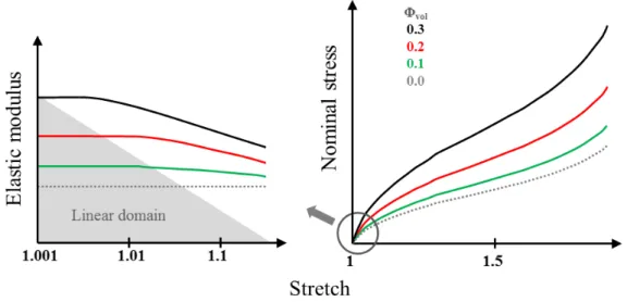
Figure 1.5: Qualitative summary of MREs elastic modulus E in the small strain
region on the left (from [Boeh01, Bel02]) and stable stress-strain behavior up to high strain on the right (from [Schu14]) for different particle volume fractions Φvol.
Along with the particle content, the particle size and shape have a significant influ-ence on the composite mechanical behavior. Below a critical particle size, usually in the nano-scale, the stiffness can be greatly enhanced whereas for a large particle size, above 10 microns, the filler influence can even be degrading [Leb02, Ram04]. Irregular and elongated particles can as well change the mechanical stress transfer throughout the material and thus the material stiffness, depending on their orien-tation within the host matrix [Fu08].
Another important aspect mainly influencing the mechanical strength is the inter-facial adhesion between the filler particles and the matrix [Dek83, Coq04, Fu08]. Indeed, at a critical stress level, debonding acts as a distinct failure phenomenon in a polymer containing rigid inclusions due to stress concentrations at the weak particle-matrix interface [Gen84, Cre01], which could be of great influence on the magneto-mechanical coupling in soft MREs.
Finally, filler networks such as the particle chains in field-structured MREs, as well as possible aggregates and agglomerates due to the fabrication process, further af-fect the composite mechanical behavior. Some amount of rubber can indeed get trapped inside the particle networks, leading to an increase of the effective filler
volume fraction and hence of the stiffness, as long as the filler network is not bro-ken down [Wan99, Yat01, Leb02]. Field-structured MREs also exhibit the highest mechanical stiffness when the load is applied in the direction of the particle align-ment [Bel02, Var05, Schu14], similar to what is classically observed in uni-directional fiber-reinforced composites [Cam10].
1.4.2 Magnetic response of MREs
Before investigating the macroscopic magnetic properties of MREs, important vari-ables, commonly used in the magnetics-related literature, will be reviewed for clarity. In vacuum, the magnetic field b0 = µ0h0 is proportionally related to the magnetic
permeability of free space µ0 = 4π10−7 [N/A2] multiplied by the externally applied
field h0. If a finite ferromagnetic7body is now exposed to this excitation field h0, the
body becomes magnetized and itself provokes a perturbation field h1, also known
as demagnetizing field or stray field [Guy94, Kan04]. The macroscopic magnetic constitutive relation then can be defined following the SI (Système International d’Unités) system of measurement as:
b= µ0(h0+ h1+ m) = µ0(h + m) , (1.1)
where b = b0 + b1 is the total magnetic field, also called magnetic induction or
magnetic flux density and expressed in Tesla [T = N/Am] and b1 = µ0(h1+ m) is
the magnetic perturbation field. h = h0+h1 is the total h-field, also called magnetic
field intensity or magnetic field strength, expressed in [A/m]. The state of magnetic polarization within the body is described by the magnetization field m [A/m]. The nonlinear relation between h and m for a ferromagnetic material can be determined experimentally and usually takes the form of a hysteresis loop (see Figure 1.6a). Hard magnetic particles and nano-scale soft ferro-particles can show an important hysteretic behavior [Lan04, Har06]. In the case of carbonyl iron particles (CIP) however, remanence magnetization and coercitive field are small (in the order of
7Within the many classifications for magnetic materials, three major groups can be distinguished,
namely diamagnetic (e.g. copper, χ ∼ −10−5), paramagnetic (e.g. aluminum, χ ∼ 10−5) and ferromagnetic (e.g. iron, χ 1) materials [Guy94]. Compared to the MRE filler particles, the elastomeric matrix, the surrounding air, etc. will be considered as non-magnetic for prac-tical purposes, but probably exhibit some very small paramagnetic or diamagnetic behavior.
1.4 Physical phenomena in MRE behavior
10−3 T, see definition in Figure 1.6a) and magnetic hysteresis is usually neglected
[Mar00]. The dimensionless volume susceptibility χ [−] corresponding to the initial slope of the m − h curve can then be introduced, as well as the following linear constitutive relations:
m= χh, b = µ0(1 + χ) h = µ0µrh= µh, (1.2)
where µr and µ are the relative and magnetic permeability of the body,
respec-tively.
Figure 1.6: a) Magnetic hysteresis loop for a ferromagnetic material (from [Dig10]):
the virgin sample is magnetized upon the application of the h-field (1) and asymp-totically approaches the saturation magnetization ms for high fields; decreasing
the h-field (2) to zero results in a non-zero magnetization called remanent mag-netization mr; the application of the field in opposite direction then leads to zero
magnetization for the coercitive field hc and the further decrease again saturates
the material. b) Qualitative summary of MREs magnetic properties for different Φvol (first quadrant, no hysteretic effects, from [Mar00]).
Standard approaches in the field of magnetics such as the superconducting quantum interference device (SQUID) magnetometer [Mar00, Kal05], the Faraday balance method [Vic02, Dig10], vibrating sample magnetometry [Lan04, Abr07], induction coil [Bos01, Dan12] and Hall effect measurements [Schu14] have been used to de-termine the magnetic response in MREs. It has been shown that the susceptibility of MRE composites is small compared to the bulk values of iron (see Figure 4.4 on page 40 in [Schu14]). Moreover, it has been observed, that the initial
susceptibil-ity as well as the saturation magnetization increase with increasing particle volume fraction (see Figure 1.6b). The latter is often assumed to be a linear function of the particle volume fraction and the saturation magnetization of the bulk particle mate-rial [Mar06, Dig10, Schu14]. The alignment of the particles in field-structured MREs further enhances the magnetic susceptibility of the material, when the magnetic field is applied in the particle chain direction [Dan12]. Finally, we note that in the few investigations of MRE magnetic properties during mechanical loading, a decrease of the magnetic susceptibility with the strain has been reported [Bos01, Lan03].
1.4.3 Magnetic field-dependent modulus
Under the influence of an applied magnetic field, MREs display a change of stiffness. This corresponds to the so-called magneto-rheological (MR) effect introduced by many researchers as the field induced change of modulus8. A lot of different results
are reported about the relative MR effect: from as low as a few percent [Boc12] up to more than a thousand percent [Ste07]. Due to the great variety of investigated materials, manufacturing techniques and testing conditions, it is difficult to compare objectively all these results. However, some tendencies regarding the field-dependent modulus can be outlined, that are closely related to the previously observed purely mechanical and magnetic phenomena:
• Generally speaking, the magneto-elastic interactions result from an overall competition between mechanical stiffness and magnetic interactions: the lower the composite’s stiffness, the higher the possible magneto-elastic effects. • The change in modulus usually increases with iron-filler content. An optimal
proportion of particles resulting from a competition between the stiffening of the material and the magnetic interactions (linear regime) is estimated between 20% and 30% particle volume fraction [Dav99, Gal12] and observed by trend in some experimental studies [Kal05, Dig10].
• The MR effect increases with increasing magnetic field; however, it saturates above a certain level of the applied magnetic field [Gin02, Kal05].
• The modulus increase tends to be highest in the small-strain region (0 − 5%) while it tends to decrease in the mid-strain region (∼ 15%) [Bos01, Bel02, Schu14].
8The absolute MR effect [M P a] is defined as the difference between the modulus for an applied
magnetic field and the modulus at zero field (either elastic or tangent) whereas the relative MR effect [%] is defined as the ratio between these two moduli.
1.4 Physical phenomena in MRE behavior
• The MR effect can be further enhanced in field-structured MREs [Bel02, Kal05, Var05].
1.4.4 Deformation under magnetic field
The coupled magneto-mechanical behavior can also be approached from another point of view, closely related to the field-dependent modulus and attributed to the very same mechanisms. The deformation exclusively due to an externally applied magnetic field can be defined as the free deformation of the MRE material. If such a deformation is restricted by imposed mechanical boundary conditions, additional work has to be expended to act upon the material, thus leading to a field-induced increase in stiffness. Experimental studies demonstrate deformations in the order of 10−4 [Gua08] up to 10−1 [Dig10], and report either stretching or contracting
of MREs along the uniform applied field [Mar06, Dan12]. This deformation due to the magnetic field is often referred to as magnetostriction. However, the term magnetostriction is rather ambiguous since it is also used in physics to describe another phenomenon, and the underlying mechanisms of such deformations have to be clarified. Henceforward, we will suppose that the applied magnetic field is static and will not consider phenomena due to time-dependent magnetic fields or deformations.
Influence of the field homogeneity on the material behavior
When characterizing MREs, a uniform field distribution within the sample should be achieved since field gradients can have an important influence on the behavior of MREs. If a magnetic material is placed in a non-uniform magnetic field, the material experiences a magnetic body force to decrease its interaction energy with the magnetic field. When a MRE composite is placed in a gradient of external magnetic field, these forces act on the filler particles. The (magnetically soft) par-ticles together with the polymer network are therefore displaced towards a higher amplitude of the field. Depending on the geometrical arrangement, elongation, con-traction, bending or rotation can be achieved and used to create motion [Zri96], for example in smart actuators [Ste13]. In experimental MRE characterization in contrast, one has to keep in mind that these parasite field gradients can lead to additional deformation of the material on top of the original MR effect. On the one hand, it is not trivial to generate uniform, external excitation fields (see Section 1.6).
On the other hand, even if we suppose that the externally applied field h0 is
per-fectly uniform, the magnetized MRE sample can further create field gradients within the specimen9. Magneto-static field equations and the corresponding boundary
con-ditions (see Chapter 3, Section 3.1) indeed prescribe the field distribution within a body, which strongly depends on its geometry, as illustrated in Figure 1.7. Only for ellipsoids of revolution and, as a special subset, for the sphere (all being finite) is the magnetization m as well as the perturbation h1 and hence the total magnetic field
buniform within the body. Thus, such bodies can be used for precise investigations
of magnetic materials [Osb45].
Figure 1.7: FEM simulation [FEMM] of the distribution of the magnitude of the
magnetic perturbation field |b1|in the first quadrant of the mid-symmetry plane
of: a) a cube (2D plane), b) a cylinder (2D axisymmetric) and c) a sphere inclusion (2D axisymmetric) surrounded by air and magnetized bottom-up along the mid-axis.
Deformation behavior under uniform magnetic field
Since the 19th century, the term magnetostriction has been used in physics to des-ignate the deformation caused by intra-granular spin-orbit interaction in crystalline ferro-magnets. A large piece of iron, for example, expands upon the application of a magnetic field though the saturation strain is in the order of 10−5 [Guy94]. This
mechanism is inherently present in the ferromagnetic filler particles of MREs. How-ever, the magnetostriction of the individual particles is several orders lower than the strains reported in MREs. Additionally, even if the applied field did create ap-preciable stresses in the stiff ferrous particles, these would not appreciably transmit
9Note that this will also influence the particle network when curing samples under magnetic field
1.4 Physical phenomena in MRE behavior
through the soft polymer matrix. Therefore, this mechanism is usually neglected in investigations of standard MREs [Mar06, Sto11] and the word magnetostriction often used in the MRE literature designates the observed macroscopic effect. Another mechanism that can arise at the microscopic scale is the rotation of the particles due to magnetic torques. Such torques apply predominantly to particles with an irregular, elongated shape and can produce strong magneto-elastic coupling. The particles indeed try to orient themselves parallel to the applied field, which tends to generate stretching of the sample in the field direction but can sometimes lead to an unstable configuration [Lan03, Lan04, Gal13a, Kar13]. Theoretically, because of their spherical shape, carbonyl iron particles cannot experience magnetic torques. However, particle aggregates can be present in MRE materials and are sometimes considered to contribute to the occurring deformations [Gua08, Sto11].
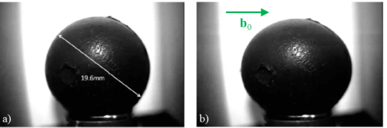
Figure 1.8: Photograph of an MRE sphere without a) and with b) an externally
applied uniform field b0 = µ0h0 = 1.2 T (green arrow). The applied field induces
an elongation in the direction of the field of 4.8% at saturation (E ≈ 0.7 MP a) [Dig10].
The remaining physical mechanisms are the magneto-dipolar interactions between the particles. To summarize, these interactions try to enhance the overall magnetic susceptibility of the body by diminishing the magnetic part of its energy, in compe-tition with the mechanical strain energy. The deformation of a MRE sample then seems to be the result of two contributions. On the one hand, determined by the overall geometry of the sample, the Maxwell stress at the discontinuity surface can induce an elongation of the MRE composite along the field. A significant strain of almost 5 percent for an MRE sphere has been reported ([Dig10], see Figure 1.8) and attributed to this so-called shape-effect, often described in terms of demagnetizing factors [Mar06, Mor09, Dig10, Zub12]. In the linear case of an ellipsoidal rigid body
(that has a uniform internal magnetic field b), if the material is isotropic or has its principal axes of magnetic anisotropy along the principal axes of the ellipsoid, the internal magnetic field b can be found analytically for a given externally applied uniform field h0. In this special case10, the internal perturbation field h1 can be
re-lated to the uniform magnetization m with the help of the so-called demagnetizing factor D as h1 = −Dm (see Figure 1.9).
Figure 1.9: Demagnetizing factor D of the oblate spheroid (0 < c < 1), the sphere
(c = 1) and the prolate spheroid (1 < c) depending on the spheroids aspect ratio and the direction of magnetization along the body’s principal axes from [Osb45]. On the other hand, the sample can change its length in the direction of the field to enhance the magnetic susceptibility determined by the local position of the particles relative to one another. As described earlier in the context of magneto-rheological fluids [Lem91] and more recently in the context of MREs [Bor01], a restoring force between a pair of particles subjected to an externally applied magnetic field tends
10Note that average demagnetizing factors for other geometries, e.g. the rectangular rod or the
1.4 Physical phenomena in MRE behavior
to align the particles with the field so that they form magnetic dipoles11. This
contribution is characteristic for MREs (shape-independent material property) and theoretically can lead to either contraction or elongation of the sample:
Figure 1.10: Schematic of the dipole interactions between a pair of particles for
different angles magnetized along e1 [Gal14].
• In isotropic MREs, the tendency is for dipole pairs aligned with the applied field (pair 1 in Figure 1.10) to approach each other, causing a contraction of the sample along the field. Dipole pairs perpendicular to the field (pair 5 in Figure 1.10) typically push each other away, reinforcing the contraction along the field, since the material is almost incompressible [Kan04, Mar06]. However, the complicated nature of the particle interactions for random, three-dimensional micro-structures could give rise to different types of coupling, and this effect seems to generate strains in the order of 10−3.
• In field-structured MREs, different possible magnetic and mechanical loading conditions further complicate the situation. If the magnetic field is applied parallel to the direction of particle chains, intuitively, there should be no or a very small deformational effect (due to possible shrinking during the fabrica-tion process). The particles have reached their preferred arrangement during curing and have been trapped in the solid matrix. If an applied mechani-cal load disturbs this state of equilibrium and changes the inter-particle dis-tances, the magnetic susceptibility decreases (as mentioned in Section 1.4.2).
For an applied pre-tension, possibly up to a certain strain threshold, the mag-netic interactions can try to restore the preferred state and the sample tends to be compressed [Coq04, Mar06, Dan12]. Conversely, for an applied pre-compression, the sample usually expands [Gin02, Dan12]. Typical values of strains in this case are in the order of 10−3.
• If the magnetic field is applied transverse to the structuring direction, the deformational effect can even be higher. Due to the presence of the particle chains normal to the applied field, the particles tend to move more significantly in order to form dipole-pairs aligned with the applied field, typically leading to an overall extension of the sample [Gua08, Dan12]. Typical values of strains here are in the order of 10−2.
Finally, note that under certain loading conditions, a uniform magnetic field can provoke extraordinary deformations of a MRE body, when a critical field is reached (onset of bifurcation). The instability of an elongated body subjected to a magnetic field transverse to its long axis can be interpreted as the well-known compass effect in magnetism [Moo68], whereby the body tends to align with the applied magnetic field (see Figure 1.11, [Rai08]). Instabilities due to a destabilizing torque are further favored when the sample’s magnetic susceptibility in the direction of the applied field is lower than the susceptibility perpendicular to the field, for example due to a field-structured particle network [Mar06, Dan14].
Figure 1.11: a) Schematic diagram and b) photographs of the deformation of a
circular membrane (1), glued along the outer boundary to a fixating panel (2) and subjected to a uniform magnetic field (green arrow) [Rai08].
1.5 Approaches to the modeling of MREs
1.5 Approaches to the modeling of MREs
The above-described complexity of the magneto-mechanical coupled behavior of MREs makes their mathematical modeling a difficult task. Geometrical non-linearities are introduced in association with the large deformations that these elastomer-based materials are capable of developing. Additionally, constitutive non-linearities due to the hysteretic behavior of the viscoelastic matrix as well as a hysteretic, satu-rating magnetic response further complicate the modeling of such composites. The approaches in the modeling of these materials can basically be partitioned into micro-mechanical or structural models on the one hand and continuum or phenomenolog-ical models on the other hand. They are briefly reviewed in the following.
1.5.1 Micro-mechanically based modeling of MREs
The first kind of model provides a micro-mechanical description of MREs. Usu-ally, the particles are considered as rigid spheres or spheroids distributed randomly [Bor01], or with a preferred alignment [Dav99, Yin06], within the elastomeric ma-trix. The magneto-mechanical interactions for a set of particles are then usually extrapolated in order to obtain the global expressions for a body. An interesting modeling approach is homogenization, that determines an effective macroscopic con-stitutive model for an MRE based on the properties of the constituent phases and their arrangement within the composite [Pon11]. The advantage of this type of models is that the mathematical expressions can provide insight into the underly-ing mechanisms responsible for the couplunderly-ing in MREs. An important disadvantage that may be mentioned is the complexity of these expressions, even when a series of simplifications is usually adopted (linear mechanical or magnetic behavior; only the fields of closely neighboring particles or isolated evenly distributed particle chains affect each other).
1.5.2 Phenomenological continuum description
The second kind of models is continuum models, that do not have to describe all the microstructural phenomena to accurately capture the material’s behavior. Since the magnetic particles are very small in comparison to the overall size of the investi-gated bodies, a continuous distribution of the particles or particle structures within the elastomer can be assumed. Some magneto-mechanical problems in MREs are solved in the framework of a relatively simple macroscopic theory, in which the
MRE composite is considered as a magnetizable elastic continuum, whose equations of magnetic and elastic state are uncoupled [Zri96, Rai08, Dig08]. Other models account for stress-induced changes in the magnetic behavior, but without a compre-hensive field theory, they are limited to one-dimensional (small) deformations or to particular geometrical shapes [Mar06, Zub12, Kar13]. Fully coupled non-linear field theories for MREs have also been developed based on only one underlying contin-uum [Dor03, Kan04, Bus08, Ogd11, Sax13]. Global balances of linear and angular momentum, energy and entropy production, plus the Maxwell equations, are used in order to find a system of partial differential equations, from which the stress, the strain, the displacement and the magnetic fields can be obtained. At the heart of these theories, a free energy density function that depends in a coupled fashion on mechanical deformations and magnetic fields describes the materials constitutive behavior and is identified with the help of experimental data. Originally formulated for isotropic MRE materials, they have been recently expanded to describe field-structured magneto-elastic continua [Bus10, Dan12]. Once the material parameters of these models have been identified, they can be easily implemented numerically to handle boundary-value problems in complex geometries and loading conditions [Dor05, Dan14]. The main problem at the moment, however, is the lack of an accu-rate experimental characterization for finite strains and magnetic fields in order to propose realistic, mathematically consistent forms for the free energy function.
1.6 Previous experimental characterizations of magneto-elastic
properties at finite strain
When characterizing MREs experimentally, the difficulty lies in the fact that (stan-dard) mechanical testing methods of elastomers [Cha94, MSC10], accounting for uniform mechanical fields within a test specimen, have to be combined with ex-ternally applied magnetic loadings inducing a uniform field distribution inside the sample. Further complicating this task, mechanical tests up to high strain and un-der high magnetic fields have to be accomplished to completely capture the behavior of MREs. To account for the magneto-elastic coupling, the magnetic material pa-rameters also have to be measured during sample deformation. Last but not least, different deformation modes should be evaluated to accurately identify the mate-rials constitutive behavior. One can find in the literature a large number of tests (quasi-static, large strains, high magnetic field) for various MRE materials. The first
1.6 Previous experimental characterizations of magneto-elastic properties at finite strain
studies regarding MREs approached their behavior in a purely experimental fashion without the idea yet of a general constitutive description in mind. In what follows, the most significant studies are classified according to the magnetic field generation. Unless otherwise indicated in Section 1.4.2, measurements of the magnetic properties – if done at all – are performed separately from mechanical ones (i.e. no coupling). Additionally, “strains” implies nominal strain and “magnetic field” designates the excitation magnetic field b0 = µ0h0 in [T ], if not otherwise specified.
1.6.1 Overview of experimental studies on MREs
Magnetic field created by permanent magnets
Probably the most simple way of applying an external magnetic field is through the use of permanent magnets. In such a setup, quasi-static double lap shear tests were performed by Shen et al. [She04] (strains up to 80%, magnetic fields up to 0.4 T ), and quasi-static compression tests by Farshad et al. [Far04a, Far05] (strains up to 30%, magnetic fields up to 0.4 T ). Schematics of these two experiments are presented in Figure 1.12a and b, respectively. Disadvantages that could be stated for this approach are that only fixed values of magnetic loads can be applied and that it is usually difficult to obtain a constant, homogenous field distribution with the help of these commonly rectangular-shaped permanent magnets.
Figure 1.12: Schematics of setups in which MREs are subjected to a magnetic field
generated by permanent magnets. a) Case of a double-lap shear test [She04]. b) Case of a compression test [Far04a].
Magnetic field created by solenoids
Static compression tests (up to 6.5% strain) under an externally applied magnetic field (up to 0.5 T ) created with a ring-shaped solenoid around the MRE specimen were performed by Kallio [Kal05]. However, due to the small length of the solenoid and the asymmetrical positioning of the sample inside it (see Figure 1.13a), non-uniform magnetic fields influenced the measurements. Bossis et al. [Bos01, Bel02], as well as Coquelle [Coq04] (see Figure 1.13b), also placed their MRE sample within a solenoid (magnetic fields of up to 0.15 T ). The elongated solenoid together with the central position of the long cylindrical sample ensured a uniform magnetic field in the region where the sample is placed. However, it blocked the access for ex-perimental diagnostics that would be needed to extract the necessary strain data characterizing field-structured MREs. Hence, only one-dimensional tensile stress-strain measurements (up to 25% stress-strain) were performed.
Figure 1.13: Schematics of setups in which MRE samples are placed within a
solenoid-generated magnetic field (green arrow). a) Case of a compression test [Kal05]. b) Case of a tension test [Coq04].
Magnetic field created by Helmholtz coil systems
Martin et al. [Mar06] designed an interesting Helmholtz coil system for deformation measurements on MREs (see Figure 1.14). Two paired solenoids create a homo-geneous magnetic field while providing access to the measurement region, despite being restricted to lower magnetic field values (up to 0.12 T ). The rectangular-shaped MRE sample (non-uniform internal magnetic fields b, b1 and mechanical
fields) is suspended from a cantilever and centered within the two coils. By adding weights to the cantilever, a constant mechanical pre-stretch could be imposed (on the sample attached on the bottom end) and a one-dimensional deformation upon the application of the magnetic field was recorded by the help of an optical apparatus.
1.6 Previous experimental characterizations of magneto-elastic properties at finite strain
Figure 1.14: a) Schematics of the Helmholtz coil uniaxial tension system designed
by Martin et al. [Mar06]. b) FEM visualization (2D axisymmetric, [FEMM]) of the distribution of the magnitude of the magnetic field |b0| generated by the
combination of both the upper and lower coils. Magnetic field created by open magnetic circuits
Another common way to perform experiments on MREs is to place the sample between the two poles of an electromagnet. Commonly, tapered pole shapes guide the nearly uniform and elevated magnetic field (above 1 T ), created by solenoids integrated in a high-susceptibility magnetic circuit, through an accessible air gap. In such a setup, double-lap shear tests (up to 10% strain, [Jol96, Gin99, Gin02, Kan07], see Figure 1.15), uniaxial deformation tests (up to 10% strain, [Kan07, Dig10]), and compression tests of an MRE cube (up to 10% strain, [Var05, Var06]) have been performed. Since this setting, adapted for uniaxial tensile tests, will be used in this study, a more detailed description of such an experimental setup can be found in Chapter 3.
1.6.2 Magneto-mechanical experimental characterization using continuum models
Just recently, some research groups have started working on a full magneto-mechanical experimental characterization for continuum models. During a PhD-thesis at the University of Glasgow, Schubert et al. [Schu13, Schu14] collected large-strain exper-imental data (up to 100% strain) for MREs under various deformation modes, both
Figure 1.15: Double-lap shear setup with the MRE sample located between the two
poles of an open electromagnetic circuit [Kan07]: a) photograph and b) schematic. without and with the application of external magnetic fields. Isotropic and field-structured MREs were prepared and tested under uniaxial compression and tension, pure shear and equi-biaxial tension (see Figure 1.16). However, due to the use of permanent magnets, the applied magnetic fields (up to 0.3 T ) were non-uniform and different in each setup. Furthermore, mechanical experimental issues were recorded (e.g. friction and buckling in compression tests and non-ideal deformation kinemat-ics in pure shear). Tough the purely mechanical response of isotropic MREs could be described by a common constitutive model (Ogden), data fitting to several trans-versely isotropic models were not successful, even in the purely mechanical case. As a consequence, neither did they proceed to characterize magneto-mechanical con-stitutive models nor did they measure magnetic material properties depending on sample deformation.
Figure 1.16: Photographs of MRE experimental setups for large strains under
mag-netic fields generated by permanent magnets: a) uniaxial compression, b) uniaxial tension, c) pure shear and d) equi-biaxial tension [Schu14].
1.7 Scope and organization of the present work
Finally, in the framework of the European project MOCOPOLY12 launched 2012 in
Germany, one objective is the continuum physics modeling, testing and parameter identification of MREs at the macroscopic scale. Preliminary quasi-static and dy-namic mechanical shear experiments for small deformations and low magnetic fields were conducted [Wal14] but no magneto-mechanical experimental results for finite strain have been published yet.
1.7 Scope and organization of the present work
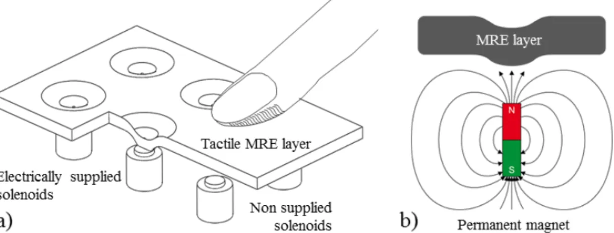
The goal of the present work is to characterize the behavior of MREs with a main focus on their coupled magneto-mechanical response up to large strains and under high magnetic fields. Having in mind the design of smart devices capable of high deformations, the phenomenological material model proposed by Kankanala, Danas and Triantafyllidis [Kan04, Dan12, Dan14] needs to be accurately identified and implemented in numerical analysis. Indeed, a large out-of-plane deformation could be achieved in response to a spatially localized magnetic field and used in haptic devices such as a tactile interface [Vid07]. For example, patterns can be displayed on a surface by placing a matrix of solenoids or permanent magnets underneath a soft MRE surface (see Figure 1.17), as already achieved with magneto-rheological fluids [Jan10, Bol11, Lee11] or electro-rheological elastomers [Kyu12].
Figure 1.17: Schematics of the working principle for tactile interfaces with patterns
created a) by a matrix of solenoids placed underneath a MRE layer or b) by a permanent magnet.
12Multi-scale, multi-physics modelling and computation of magneto-sensitive polymeric materials;
With the purpose of achieving a coupled magneto-mechanical characterization of MREs behavior for the development of a tactile interface, this work encompass experimental, theoretical and numerical developments. These topics are detailed in this manuscript as follows:
• In Chapter 2, aspects pertaining to the fabrication of MRE samples are pre-sented. Material selection, fabrication process of isotropic and field-structured MREs, as well as sample design and particle/matrix compatibility are dis-cussed.
• Chapter 3 covers the actual magneto-mechanical characterization. After intro-ducing the general theoretical framework for transversely isotropic magneto-elastic continua, the coupled magneto-mechanical constitutive laws for both isotropic and field-structured MREs are derived in order to determine the sets of material parameters to be identified in each case. The second part of this chapter is dedicated to the experimental characterization of MREs thanks to a specially designed experimental setup allowing tensile tests up to large strains and up to high magnetic field.
• In Chapter 4, the identified MRE material models are integrated into a finite elements numerical analysis. The existing theoretical framework is extended to the axisymmetric case so as to predict the behavior of MRE layers subjected to a spatially localized magnetic field and the obtained numerical results are compared to an actual prototype device.
• Finally, Chapter 5 provides concluding remarks as well as perspectives for fu-ture work regarding the specific subjects treated in this thesis.
Chapter 2
Materials and samples
In this chapter, after a brief reminder of the state-of-the art in this domain in Section 2.1, all the aspects pertaining to the fabrication of the samples are covered. In Section 2.2, first the design of samples adapted to a coupled magneto-mechanical characterization is discussed. Material selection and general fabrication procedures are then presented in Section 2.3. Additionally, the interfacial adhesion between particles and matrix is investigated in detail in Section 2.4 in order to settle upon whether a pretreatment of the particles is needed in the rest of the study. The chapter is closed by a conclusion in Section 2.5.
2.1 Introduction
Magneto-rheological elastomers (MREs) are typically composed of micron-sized mag-netizable particles dispersed in an elastomeric matrix. Within the class of elas-tomers, different stiffnesses can be targeted according to the intended use, from very soft silicone rubber for large-strain applications [Ber00] to relatively harder polybutadiene rubber [Sun08] for damping applications. Elastomers are made of macromolecular chains weakly bonded to each other. Their fabrication usually in-volves mixing two viscous liquids, the elastomeric non-bonded chains, often named Part A, and a catalyzer, named Part B, that triggers the cross-linking (also called vulcanization) of the macromolecular chains by creating bonds between them in order to obtain the final solid elastomer material. Depending on the elastomer formulation, cross-linking can be obtained via different chemical catalyzers (sulfur, platinum, ...) and can either happen at room temperature or require heating or even exposure to UV light during a specific curing time [Gen12].
The majority of fillers used in MREs are soft micrometric iron particles; magnetically “soft” meaning that they do not retain magnetization once the magnetic field is turned off. These particles are often spherical monodisperse carbonyl iron particles
(obtained by thermal decomposition of pentacarbonyl iron) of diameters ranging from 0.5 to 40 µm [Var06, Wan06, Boes09, Dan12], though the smaller end of the spectrum is favored to avoid degrading effects [Leb02, Ram04]. In MREs fabrication process, the micrometric particles are added to the uncured elastomer constituents and the obtained compound needs to be thoroughly mixed and degassed, before curing can be conducted in a mold of the desired shape.
Following the observation that particles arrange themselves in chain-like structures along the lines of the magnetic field in magneto-rheological fluids [Car00], researchers in the field of MREs have applied a homogeneous magnetic field to the elastomer composite during cross-linking. This also led to the formation of chain-like particle structures, which remained locked in place upon final curing [Car00, Kal05, Li08]. Hence the application or non-application of a magnetic field during curing gives the possibility to produce either transversely isotropic or isotropic samples, respec-tively.
As mentioned in the general introduction (Section 1.4.1), another important aspect influencing the strength of the composite material, especially under large deforma-tions, is the interfacial adhesion between the filler particles and the matrix material [Dek83, Fu08]. Indeed, at a critical stress level, debonding acts as a distinct failure phenomenon in a polymer containing rigid inclusions due to stress concentrations at the weak matrix interface [Gen84, Cre01]. In order to modify the particle-matrix interactions and more precisely to improve the interfacial adhesion for a given particle size, the modification of the surface properties of the system has been suggested [Zha07, Leg08]. Some studies showed the improved bond strength be-tween primed metallic surfaces and addition-cured silicone elastomers [Pei04], and different kinds of silane coupling agents have already been used in MREs at mod-erate deformations [Coq04, Coq06b, Wan06, Fan10]. A silane coupling agent or primer typically consists of two different reactive groups located at either end of the active molecule, one compatible with the filler particles and the other one with the elastomer matrix. Applied in a thin, theoretically monomolecular layer, the primer serves as an adhesion promoter between the two initially non-bonding sur-faces [Hab06]. Although the phenomenon of interfacial adhesion appears as a key property for the behavior of filler-soft elastomer composites, interfacial adhesion at high tensile deformations in soft MREs has rarely been investigated in detail. Finally, due to the scarcity of coupled magneto-mechanical characterization existing in the literature, there has been so far, to our knowledge, no typical or ideal sample
2.2 Sample shape for coupled magneto-mechanical testing
specially devised for such a coupled characterization (see Section 1.6 in the general introduction). Indeed, particular attention to the sample shape was only mentioned in studies investigating the shape effect (see Section 1.4.4, [Dig10]) under purely magnetic loading. Considering that coupled magneto-mechanical characterization is the main goal of the present study, the crucial topic of the sample shape is addressed in the next section of this chapter.
2.2 Sample shape for coupled magneto-mechanical testing
In order to ensure reproducibility in material testing, norms provide guidelines for sample shape design depending on both the tested material and the type of loading. Behind a sample’s shape for material properties evaluation lies the Saint Venant’s principle according to which the difference between the effects of two different but statically equivalent loads becomes very small at sufficiently large distances from the load [Sai1855]. Practically, this means that for long tensile samples, the stress is homogeneous in the gage area of the sample far away from the clamping. If the sample is to be shorter, stress localization at the clamping needs to be attenuated by smooth root-corner radii from the sample’s head to its gage area, hence yielding the well-known dog-bone (or dumbbell) samples for tensile testing. For elastomers tested in tension, the corresponding (equivalent) norms are the American ASTM D4121and
its European counterpart ISO 372. Some guidelines from the latter are reported in
Figure 2.1, where the maximum recommended thickness is 3 mm for ISO 37-1 and 2.5 mm for ISO 37-2. Additionally, the cross-section of both samples is rectangular since in polymer testing, samples are often punched out of large sheets of the material of interest.
Figure 2.1: Sample shape design guidelines from [ISO37] norm: a) ISO 37-1 and b)
ISO 37-2. Dimensions are in millimeters. Though not represented, both samples have a rectangular cross-section.
1Standard Test Methods for Vulcanized Rubber and Thermoplastic Elastomers-Tension. 2Rubber, vulcanized or thermoplastic - Determination of tensile stress-strain properties.
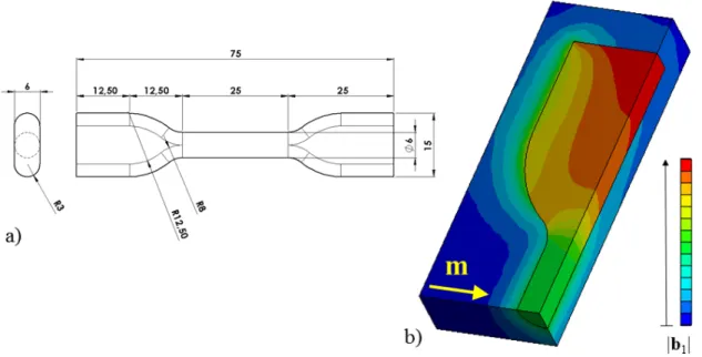
Provided that some of the samples are cured inside a magnetic field produced within a 82 mm air gap, there are restrictions regarding the length of the sample orienting the choice towards the ISO 37-2 dimensions (see Figure 2.1b). However, a 4 mm width might be too narrow for the markers that are done on the sample for video extensometry (see Chapter 3, Section 3.3.3) to be distant enough from the borders of the sample and hence to be free from edge effects. Thus, following the ISO 37-1 norm, the gage area and heads width of the ISO 37-2 norm are enlarged to 6 mm and 15 mm, respectively (as sketched in Figure 2.2a), in order to get a good compromise between the described restrictions and the need for a homogeneous state of strain and stress in the gage area of the sample during mechanical tensile tests. The sample thickness is set to the maximum of 3 mm.
Figure 2.2: a) Dimensions, in millimeters, of the flat dog-bone sample ensuring a
homogeneous state of stress in its gage area during mechanical tensile tests on MREs. b) 3D FEM simulations [ANSYS] showing the magnitude of the mag-netic perturbation field |b1| in a flat dog-bone magnetic sample magnetized (m)
transverse to its longitudinal axis.
However, as mentioned in the general introduction in Section 1.4.4, the shape of a body greatly influences the distribution of the total magnetic field b – even when submitted to a uniform external magnetic field b0. A numerical simulation,
per-formed with the commercially available Finite Element Method (FEM) software [ANSYS] and reported in Figure 2.2b, shows that the magnetic perturbation field
b1 (and thus b when the sample is magnetized by a uniform external magnetic field
b0) is unfortunately not homogeneous in the gage area of the flat dog-bone sample
![Figure 1.7: FEM simulation [FEMM] of the distribution of the magnitude of the](https://thumb-eu.123doks.com/thumbv2/123doknet/2797431.66061/25.892.152.785.362.591/figure-fem-simulation-femm-the-distribution-the-magnitude.webp)