Science Arts & Métiers (SAM)
is an open access repository that collects the work of Arts et Métiers Institute of
Technology researchers and makes it freely available over the web where possible.
This is an author-deposited version published in: https://sam.ensam.eu Handle ID: .http://hdl.handle.net/10985/11242
To cite this version :
Wael YOUNES, Eliane GIRAUD, Ahmed ZOUARI, Philippe DAL SANTO, Sjoerd VAN DER VEEN - Creep age forming of Al-Cu-Li alloy: Application to thick sheet forming of double curvature aircraft panel - 2016
Any correspondence concerning this service should be sent to the repository Administrator : archiveouverte@ensam.eu
aCorresponding author: wael.younes@irt-jules-verne.fr
double curvature aircraft panel
Wael Younes 1,a, Eliane Giraud2, Zouari Ahmed2, Philippe Dal Santo2 and Sjoerd van der Veen3
1IRT Jules Verne, Chemin du Chaffault, 44340 Bouguenais, France
2LAMPA, ENSAM, 2 boulevard du Ronceray, 49035 Angers Cedex 01, France
3Airbus Structures Research, Materials & Processes, 18 rue Marius Terce, 31300 Toulouse, France
Abstract. Creep-age-forming of a thick Al-Cu-Li sheet is studied. An industrial stamping press is used to form a double curvature panel at a reduced scale. This forming, which includes several relaxation steps, is modelled using ABAQUS. A material model describing an elasto-viscoplastic behaviour with anisotropy effect has been identified and implemented in ABAQUS using Fortran subroutine. The numerical model is validated by comparing experiments and numerical results in terms of deformed shapes and an improved forming cycle is suggested.
1 Introduction
In recent years, lightening aeronautical structures is one of the main axes of improvement. An interesting perspective is to add lithium to conventional aluminum alloys, which improves their mechanical characteristics and reduces their density [1]. The aluminum-copper-lithium alloy (Al-Cu-Li) is one of these materials recently developed. However, its formability by hot or cold sheet forming processes is not well known. Numerical simulations are generally used to predict the final shape of the formed parts. But, the quality of the prediction is directly linked to the material laws implemented in the codes which must describe as precisely as possible the alloy behavior under the thermomechanical process conditions.
Generally, the Creep-Age-Forming (CAF) process [2] includes four main stages: (i) the heating of the sheet until an ageing temperature (here, 150°C); (ii) the deformation of the sheet by applying a pressure on its upper surface using a punch; (iii) the ageing phase in which the sheet, always clamped between the die and the punch, is held at high temperature and stress relaxation occurs and (iv) the cooling of the sheet. Thus, during the forming cycle, two metallurgical phenomena occur: stress relaxation and age-hardening. It is therefore possible to underline the main advantages of this type of process: low springback (due to stress relaxation) and forming procedure simplification (due to the change of microstructure generated during the forming cycle).
In this study, the Al-Cu-Li alloy has been characterized under thermomechanical conditions representative of the forming cycle and modeled using classical laws (in first approach). A numerical model has then been developed using the ABAQUS software and
used to simulate the experimental forming of a double curvature panel performed on an industrial press. After the validation of this model by comparing experimental and numerical results, an improved forming cycle is suggested.
2 Characterization of the Al-Cu-Li alloy
2.1 Experimental procedureTwo types of experiments have been performed: tensile experiments and relaxation experiments. The testing conditions are given in Table
1
.Tensile tests have been performed on plate specimens at different strain rates. They allow identifying the yield locus criterion parameters and studying the strain rate dependence of the material behavior. Tensile specimens were taken from the quarter of the sheet thickness and in three directions α (0°, 45° and 90°).
Relaxation tests were carried on round specimens at different level of strains. The specimens are maintained during 8h at a given level of strain and the stress evolution as a function of time is registered. The holding time for the relaxation corresponds to the duration of the age-hardening treatment for the studied alloy.
For each type of experiments, a Gleeble 3500 was used. The specimen was heated by Joule effect at 10 K/s until the fixed temperature (150°C). The temperature was measured by a K-type thermocouple welded in the central part of the sample. The experiment was started after a holding time of 20s at the test temperature to ensure a homogeneous temperature in the specimen.
MATEC Web of Conferences
Table 1.Testing conditions
Tensile experiments Temperature (°C) 150 Strain rate (s-1) 10-1 10-2 5.10-3 Direction α (°) 0 45 90 0 45 90 0 45 90 Relaxation experiments Temperature (°C) 150 Strain rate (s-1) 10-2 Strain level 4% 8% 12% 16%
2.2 Experimental results and discussion
Experimental results are normalized by means of a reference state corresponding to the yield stress σ0 measured in the rolling direction.
2.2.1 Anisotropy and viscoplasticity
Normalized stress-strain curves obtained after tensile tests performed at 150°C with different strain rates are shown in Figure 1. The alloy exhibits strain hardening: stress increases continuously until the fracture of the specimen. The orientation α has not great influence on the material behavior. It seems however that the orientation of 45° leads to the lowest stress and highest strain at failure. It is also possible to notice that the alloy does not show a strong viscoplastic behavior: the same level of stress is reached whatever the considered strain rate.
2.2.2 Relaxation
Normalized stress-time curves obtained at 150°C after relaxation experiments at different strain levels are shown in Figure 2. The stress evolution shows two zones. The first zone is illustrated by a fast decrease in stress until a stable value 45% lower than the initial one. In this second zone, the stress keeps a constant value. The decrease rate of the stress in the first zone is the same for all tests: a period between 1500 and 1600 seconds is necessary to reach the second zone.
(a)
(b)
(c)
Figure 1.Normalized stress-strain curves obtained at 150°C for three orientations and with a strain-rate of (a) 10-1, (b) 10-2 and (c) 5x10⁻³ s-1
Figure 2.Stress relaxation as a function of time with different strain rate
Zone1
This evolution in two zones of stress as a function of time has already been observed in aluminum alloys [3]. As explained by Chen et al. [3], the stress drop is linked to a decrease of the dislocations speed, and the stabilization of the stress is due to the cessation of the dislocations movements since precipitates are formed in advance.
3 Forming of a double curvature panel in
Al-Cu-Li
(a)
(b)
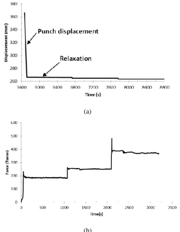
Figure 3. (a) Experimental punch displacement as a function of
time, (b) Experimental punch force as a function of time
The hydraulic press of IRT “Jules VERNE” has been used for stamping the double curvature panel. The sheet dimension is about: 1000x550x40mm. The forming process is performed in three sequences composed of a forming step followed by a relaxation phase (Figure 3.a). During the two first sequences, the displacement of the punch is monitored without restriction on the force. In the final stage, a limit force of 500T is fixed (which corresponds to the maximum performance of the press). A Coulomb friction coefficient of about 0.2 is ensured between the sheet and the die and between the sheet and the punch by applying a boron nitride powder on both sides of the sheet.
The measured punch force evolution during the forming process is shown in Figure 3.b and is in agreement with the three sequences describes above. The maximum force reached during the last sequence is of 480T (and not 500T as asked) due to the precision of the press control system. It is also possible to notice that the
threshold stress during relaxation phases is generally reached after 200s.
Figure 4. Experimental formed part
A picture of the formed part is shown in Figure 4. It is possible to note that the forming cycle applied on the sheet does not allow to fill completely the die and that the double curvature is not clearly visible: a strong springback occurs.
4 Numerical simulation of the forming
process
4.1 Material models
Two different models have been used: one for the forming phase and one for the relaxation phase of each sequence.
For the forming phase of each sequence, an elasto-plastic model with anisotropy criterion is used. The elastic behavior is described by a Young modulus previously identified as a function of temperature: a decrease of 7% of its value is found when the temperature increases from 25°C to 150°C. The plastic behavior is described using a tabulated law from the stress-strain curve obtained experimentally. The anisotropy criterion of Hill48 [4] has also been identified using the experimental data previously obtained.
For the relaxation phase of each sequence, a classical power law implemented in ABAQUS thru the Creep user subroutine has been used:
𝜀̇ = 𝐴𝜎𝑛 (1)
The module A and the exponent n were identified from the experimental tests.
The material model has been validated by simulating tensile experiments followed by a relaxation step at different level of strains.
4.2 Numerical model
A 3D model of the forming process (Figure 5) of the double curvature panel has been realized in ABAQUS. A half of the part is considered with a symmetry boundary condition along the Y-axis. The punch and the die have been modeled as discrete rigid surfaces. A displacement along the Z-axis has been imposed on the punch positioned above the piece. The die has been fixed below the sheet. After stamping, a displacement along the Z-axis has been applied in order to release the punch action on the sheet which allows the springback. A
MATEC Web of Conferences
C3D8H element type with full integration is used. The size of each element is about 13x13x7mm3. The
numerical forming steps and the Z-axis displacement conditions are controlled by specific amplitude curves that describe exactly the different forming stages programmed on the machine during the experimental test.
Figure 5. 3D model of the forming process
4.3 Numerical results
The simulated punch force evolution as a function of time is shown in Figure 6. A fill rate of only 99.67% has been obtained by following the experimental strategy of stamping. The fill rate is defined as the ratio of displacement allowing 100% of filling to the actual displacement.
Figure 6. Numerical force as a function of time
The final shape has been reached after three increasing forming phases, each followed by three relaxation steps as seen in Figure 6. A numerical springback value of 13.5mm has been evaluated by measuring the distance between the lower surface of the deformed sheet before and after the springback (Figure 7) while the measure of experimental shapes gives a springback value of 21 mm. This difference can be explained by the experimental measurement technique which must be improved and the actual material model that doesn’t take into account the kinematic hardening.
Figure 7. Springback after numerical forming and relaxation
5 Comparison between experimental
and numerical results
5.1 Force evolution as a function of time
A comparison between experimental and numerical force evolution is given in Figure 8. A good prediction of the effort is obtained with a maximum error of 5% in the final forming step.
Figure 8. Comparison between experimental and numerical
results
5.2 Contact zones on the upper surface
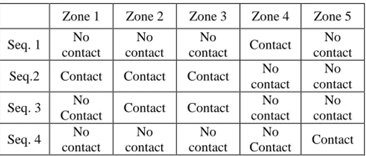
Figure 9 shows the contact play between the punch and the sheet for each sequence of the process. As summarized in Table 2, the contact play evolves continuously during the forming in different zones of the sheet (defined in Figure 10). During sequence 1, contact is present only in the central zone. During sequence 2, contact is present on the majority of the sheet except in the central zone and on the edges of the sheet. During sequence 3, some loss of contact occurs and the edges of the sheet are always not in contact. During sequence 4, the edges of the sheet are in contact with the punch.
Table 2. Contact play evolution
Zone 1 Zone 2 Zone 3 Zone 4 Zone 5
Seq. 1 No contact No contact No contact Contact No contact
Seq.2 Contact Contact Contact No
contact
No contact
Seq. 3 No
Contact Contact Contact
No contact No contact Seq. 4 No contact No contact No contact No Contact Contact Punch Die (fixed) Sheet Ysym 13.5 mm Lower surface (Before springback) Lower surface (After springback)
(a) (b) (c) (d)
Figure 9. (a) Seq.1, (b) Seq.2, (c) Seq.3, (d) Seq.4
These numerical results are compared to the experimental results. As visible in Figure 10, the boron nitride coatings is modified on some zones of the sheet, this is due to the contact with the punch. The confrontation between numerical and experimental results, in terms of contact zones, shows a good prediction of these zones by the simulation.
Figure 10. Experimental contact zones of the upper sheet
5.3 Contact zones on the lower surface
The observation of the lower surface of the sheet (i.e. the zone theoretically in contact with the die) does not shown a modification of the boron nitride coating except on the edges of the sheet (Figure 11.a). These contact zones are in agreement with the numerical results (Figure 11.b) and confirms that the filling is not complete.
(a) (b)
Figure 11. Contact zones on the lower part of the sheet, a-
experimental result, b- numerical result
6 Proposition of an improved forming
cycle
Based on the previous observations, two conclusions can be made:
(i) The forming cycle applied on the thick sheet has not allowed a complete forming of the double curvature panel. Thus, a modification of the forming cycle is necessary;
(ii) The numerical tool developed above is in good agreement with the experimental results. Thus, this model can be used to find the most appropriate forming cycle;
The principle of the new forming strategy is to relax the sheet during 1000s every time the maximum force of the press is reached (500T) until obtaining a filling rate of 100%.
An ABAQUS user subroutine UAMP has been developed to drive the loading force. The subroutine uses a numerical force sensor that has been defined at the punch reference point. When the force reaches the maximum set value, the punch velocity is set to zero allowing the material relaxation.
Figure 12. Numerical force evolution with the new strategy
The result of the simulation is provided in Figure 12 which shows punch force evolution as a function of time. It is observed that the force in the first step exceed 500T. This due to the large time increment that is automatically imposed by ABAQUS at the beginning of the analysis. But, it can be underlined that twelve forming/relaxation sequences are necessary to obtain the appropriate shape (with a limited springback).
Conclusion and perspectives
A double curvature panel has been realized by Creep-Age-Forming at 150°C on a 40mm thick sheet in Al-Cul-Li. A numerical model with ABAQUS software has been developed to predict the forming of this part following the forming cycle applied (i.e. several forming/relaxation sequences). A material model describing an elasto-viscoplastic behavior with anisotropy effect has been identified and implemented using Fortran subroutine. This model has been validated since numerical results are in good agreement with experimental results in terms of force punch and contact zones (punch/piece and die/piece). A new forming strategy has been finally proposed in order to obtain the best shape part.
Future works will consist in: (i) modeling kinematic hardening for a good prediction of the springback and (ii) developing a unified law to take into account the forming and relaxation phases in the process cycle control. Zone 3
Zone 5
Zone 1 Zone 4
Zone 2
MATEC Web of Conferences
Acknowledgments
This paper is part of the METAFOR project managed by IRT Jules Verne (French Institute in Research and Technology in Advanced Manufacturing Technologies for Composite, Metallic and Hybrid Structures). The authors wish to associate the industrial and academic partners of this project; respectively ACB, STELIA, AIRBUS, CONSTELLIUM, ENSAM.
References
1. R.J.H. Wanhill, Status and prospects for
aluminium-lithium alloys in aircraft structures, Int. J. Fatigue
16, 3-20 (1994).
2. L. Zhan, J. Lin and T.A. Dean, A review of the
development of creep age forming: Experimentation, modelling and applications, Int. J. Machine Tools &
Manufacture 51, 1-17 (2011)
3. J.F. Chen, J.T. Jiang, L. Zhen, W.Z. Shao, Stress
relaxation behavior of an Al- Zn–Mg–Cu alloy in simulated age-forming process, J. of Mat. Proc.
Tech. 214, 775-783 (2014).
4. R. Hill, A theory of the yielding and plastic flow of
anisotropic metals, Proc. Roy. Soc. Lond. Series A,