Science Arts & Métiers (SAM)
is an open access repository that collects the work of Arts et Métiers Institute of
Technology researchers and makes it freely available over the web where possible.
This is an author-deposited version published in:
https://sam.ensam.eu
Handle ID: .
http://hdl.handle.net/10985/11019
To cite this version :
Lazhar HOMRI, Jean-Yves DANTAN, Guillaume LEVASSEUR - Comparison of optimization
techniques in a tolerance analysis approach considering form defects - In: 14th CIRP Conference
on Computer Aided Tolerancing, Suède, 2016-05 - Procedia CIRP - 2016
Any correspondence concerning this service should be sent to the repository
Administrator :
[email protected]
14th CIRP Conference on Computer Aided Tolerancing
Comparison of optimization techniques in a tolerance analysis
approach considering form defects
Lazhar Homri*, Jean-Yves Dantan, Guillaume Levasseur
LCFC, Arts et Métiers ParisTech, ENIM, HESAM, 4 rue Augustin Fresnel, 57078 METZ CEDEX 3, France
*Corresponding author. Tel.: +33387375430; fax: +33 3 87375470. E-mail address : [email protected]
Abstract
In tolerancing analysis area, the most various existing approaches do not take form defects of parts into consideration. As high precisions assemblies cannot be analyzed with the assumption that form defects are negligible, the paper focuses in particular on the study of the form defects impacts on the assembly simulation and that by comparing two optimization algorithms (iHLRF and Quapro). The study is limited firstly to the cylinders. For the optimization, two main types of surfaces modelling are considered: difference surface-based method and real model. The compared models allow assessing the non-interferences between cylinders with form defects, potentially in contact. This is in the main issue to validate a tolerance analysis approach.
© 20© 2016 16 TThe he Authors. PublAuthors. Published by Elseished by Elseviervier B.V B.V.. This is an open access article
Peer-review under responsibility of the organizing committee of the 14th CIRP Conference on Computer Aided TolerancingKeywords:
Tolerance analysis; form defects, optimization, iHLRF, difference surface
1. Introduction
It is impossible to manufacture perfectly formed parts. There will always be inaccurate dimensions and imperfect surfaces. Although the inaccuracies and imperfections might be reduced till they are negligible the production cost would be raised prohibitively. However, the designer can allocate tolerances which state how much variation from the nominal shape can be tolerated if the part is to function satisfactorily.
Tolerance analysis of mechanical assemblies, essential part of design and manufacturing, is used to highlight their effects on assembly quality. The appropriate allocation of tolerances among the separate parts in an assembly can result in lower costs and higher probability of fit, reducing the number of rejects. Analyzing the cumulative effects of these tolerances on critical clearances or fits in the assembly is necessary to ensure the compliance of a product in terms of functional conditions [1,2].
To simulate the geometric deviations, various existing approaches (traditionally, statistical or by domains) consider mostly that form defects of individual parts in the assembly are neglected and are not taken into consideration. However, the non-consideration of form defects of parts could lead to noncompliant assemblies though all parts respect the geometrical specifications [3]. More generally, this consideration in the tolerancing activities, allows to highlight the form defects impacts when computing the probability of assembly and when assessing the quality and the cost of products [4,5].
This paper aims to highlight the impact of form defects consideration on the assembly simulation via mathematical optimization. In the following, we limit ourselves to cylinders example and cylindrical joints. Many different modes of form defects can be generated in these surfaces regarding to their two main features (axis and radius). In the first part of the article, an overview of the tolerance analysis issues and form defects consideration is given; the second
part deals with the consideration of form defects when assembly simulation. A comparison between two optimization algorithms applied on a cylindrical joint is proposed. An application of tolerance analysis approach taking form defects on an over-constrained mechanism is described at the end of the article. We put forward the following physical hypotheses:
• surfaces are considered with form defects and are identified by their meshes,
• no local strain in surfaces in contact,
• no deformable parts.
2. Mechanical tolerance analysis issues and form defects consideration
Geometrical deviation or variation is defined by a displacement between two any surfaces in a mechanical system. Each real surface can be modeled by a substitution surface. The model of substitution surfaces is based on the assumption that form defects are generally negligible. Generally, the relative position (position, orientation) between any two surfaces in the mechanical system is determined by the relative position between two substituted surfaces. The model will not be selected for surfaces modeling when dealing with form defects.
Skin model provides a global representation of the real surfaces including all deviations [6]. The representation of the skin model was investigated recently. A framework for skin model simulation was developed by Schleich [7]. Some examples of skin model representation can be found in [8].
For tolerancing activities, form defects are dealt in different existing models and are generated according to different techniques. Huang proposed a based decomposition method called Discrete-Cosine Transformation (DCT) to represent various manufacturing defect patterns with different modes [9]. Raja and Radhakrishnan introduced the Fourier series decomposition method based on Discrete Fourier Transform (DFT) for discrete objects [10] in order to describe the forms of a cylinder and identify specific types of defect shapes. Samper et al. [5,11] developed the Discrete Modal Decomposition (DMD), based on the eigen-shapes of natural vibrations of surfaces. In all reviewed techniques, a global generated form defect in a surface is defined by a random combination of the elementary modes.
The behavior modeling, an element key of tolerance analysis approaches, consists at the definition of the mathematical models which characterize the system behavior with deviations. Building a behavior model allows to know how features of mechanisms interact. Here, mathematical formulation (set of constraints) can be deduced from a simplified characterization of the behavior by a graph
[12]. These relations resulted from the topological loops of the graph. The mathematical representations include some specific dimensional parameters, gaps and tolerances. The behavior modeling of a planar joint taking form defects into consideration can be modeled by the concept of gap hull and the introduction of the difference surface concept [13]. Other matting solutions for circular or prismatic joints can be found in [4].
A tolerance analysis approach should define the mathematical formulation that can be able to take into account all the characteristics of the behavior model. Different methods have been proposed and are generally classified into two main categories: statistical approaches and deterministic approaches.
• Statistical approach: the goal is to compute the probability that all requirements can be satisfied under given individual tolerances [14,15].
• Deterministic approach: the goal is to
determine the dimensions and the tolerances such that any possible combination produces a functional assembly. We can for example mention the models based on geometrical constraints handling. Associated mathematical representations can thus be defined by domains [16], polytopes [17] or T-Maps®[18,19].
3. Form defects consideration in a cylindrical joint analysis
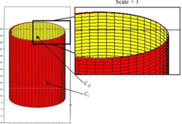
In this part, elementary form defects of cylinders are generated by translation application on the meshes- nodes of the surfaces. Different modes are thus built and a global form defect is expressed as a combination these elementary modes. The amplitudes of the modes are randomly defined. Fig. 1 illustrates a cylindrical pair joint including form defects. Cylinders are assigned by numbers 1 and 2 for the shaft (red) and the bore (blue) respectively.
For the assembly analysis, the same mesh size (same number of nodes) is considered. The nodes are here assigned by a one-to-one application between the two cylinders and are expressed in a given direction. Therefore, the nominal cylinders have different lengths so the longest cylinder is truncated and re-meshed in order to take into account only the functional surface in the contact.
the concept of clearance torsor (SDT) [20] aims generally to characterize the relative displacements between surfaces potentially in contact. The clearance torsor associated to this analysis is defined by (1):
{ }
O O 0 0 u v α β ½ ° ° = ® ¾ ° ° ¯ ¿ T (1)Where u v and , α β, define respectively the
translations at a point O and the rotations along x and y -axis.
Fig. 1. (a) Nominal surfaces, (b) surfaces with form defects
The contact between surfaces is assessed by mathematical optimization which consists to verify, by determining the clearance torsor components, if the two cylinders interfere with each other. Two types of surfaces modelling are considered for optimization: a real model defined by the real surfaces with their form defects and a difference surface-based model associated to the building of a “difference surface” which can takes into consideration all stacked form defects of surfaces in contact.
3.1. Surfaces modelling in a tolerance analysis approach
The main objective of the proposed difference surface-base method is to simplify the tolerance analysis approach by considering only superimposed form defects of the two cylinders when assessing the contact position. The distance can be thus computed between the points of the difference surface and one of the perfect cylinders I accordance with the following rule:
Rule: the nominal surface assigned by an even index is considered to define the difference surface with superimposed form defects; the nominal surface assigned by an odd index remains perfect.
In a second way, the real model can be also considered in a tolerance analysis approach. The two models are generally equivalents. The equivalence was recently proved for a 2D planar joint by Samper et al. [21]. Here, let C and 1 C two nominal cylinders in 2
contact and letN1∈C1and N2∈C2 . M and 1 M2
define the correspondent points in the cylinders with form defects as shown in fig. 2. We denote by Mdf
one point in the associated difference surface.
Fig. 2. Distance between surfaces with form defects consideration
The distances between surfaces considering the difference surface-based method and the real model
are respectively denoted by δ = N Mdf 1 df and
1 2 df
δ = M M . Analytically, the equivalence between
the two models can be expressed by (2):
1 1 2 1 2 r df df δ δ = = + + = + − = + = 1 2 1 2 2 2 1 2 1 2 M M M N N N N M N N u u N N N M (2)
The optimization problem introduced in this part allows determining the clearance torsor components (1) and requires the definition of the signed distance between cylinders, see fig. 3. Negative values of the distance represent the interferences between surfaces. Nevertheless, the occurrence of interferences in the initial configuration does not imply the non-assembly, but an analysis should be carried out. The signed distance denoted d is defined by the scalar product:
.
d=M M n1 2 (3)
Where n the outward pointing vector normal to the
surface C in the point 1 M . 1
3.2. Optimization problem : simple joint
The aim of this section is to deal with two optimization algorithms: iHLRF and Quapro. The algorithms will be compared in terms of computing time and of results accuracy.
Zhang and Kiureghian [22] developed the iHLRF algorithm by introducing a non-differentiable merit
function and by using the Armijo rule to select the step size in the linear search. Quapro algorithm is a linear quadratic programming solver proposed in the ATOMS module. It is based on the QR-decomposition method and the Chloesky factorization of the Hessian matrix of constraints for optimization [23].
Using these two algorithms, the above signed distance (3) is to be minimized or to made zero. Fig. 4 illustrates the application of the iHLRF algorithm on a simple cylindrical joint and considering difference surface-based model. The algorithm converges just after 8 iterations and the clearance torsor components are determined and controlled according to the numerical value of the signed distance.
Quapro allows determining all the components of the clearance torsor with a precision around 4
10 mm− . It includes a stopping criterion and converges in 80 iterations, which means 10 times more than iHLRF algorithm. The Quapro programming has the advantage that it not depends on a gradient calculation as iHLRF. It is here clear that the two algorithms converge similarly, a comparison between the computing time of the two algorithms in accordance to the meshes sizes is give in the fig. 5.
The fig. 5 shows that iHLRF algorithm has a linear computing time representation however it is difficult to predict the computing time of Quapro. The probability of assembly can be thereafter evaluated via a Monte Carlo method with an appropriate numbers of simulations equal to 1000 points randomly generated and that for two cases of ISO fits, see Table 1.
Table 1. Assembly probabilities for iHLRF and Quapro algorithms
iHLRF Quapro ΔP
Case 1 56,4% 57,6% 1,2%
Case 2 51,6% 54,0% 2,4%
The table 1 shows two different levels of convergence of the two algorithms. The difference remains no significant
(
Δ <P 3%)
. This returns to the ability of Quapro to control and to manage the degenerated points. Quapro can be therefore used to determine the torsor components (1) when a cylindrical joint analysis is asked.In order to evaluate the form defects impacts on the optimization problem, a numerical analysis is performed. For small form defects, the distance is lightly positive then it becomes increasingly negative. If the form defect exceed 0.00525 mm, the distance
can takes values below 4
10−
− . The numerical study
takes into consideration the two models of surfaces.
4. Comparison between the two algorithms: application to an over-constrained mechanical system
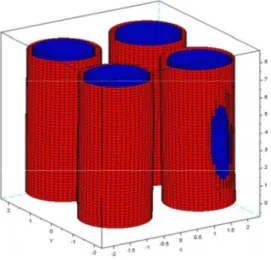
The considered optimization algorithms are in this section applied on a simplified example assembly of an industrial electrical connector. The mechanical system is made up of two parts on which 4 cylindrical pair joints (4 pins must get into their pin holes) are defined. By considering only functional surfaces, each surface can be characterized by a cylinder.
The comparison between the optimization algorithms proposed for a simple cylindrical joint in the previous part of the article will be reapplied here. The clearance torsor is expressed in a global base of the system and it characterizes the relative displacements between the “holes” part and the “pins” part.
The four cylinders are parallels. That can remove a degree of freedom defined by the rotation along z−
axis. The clearance torsor, defined in a global base, can therefore be written as (4):
{ }
O O 0 u v α β γ ½ ° ° = ® ¾ ° ° ¯ ¿ T (4)Fig. 4. Perfect cylinder C1 and displacement of the difference surface
df
C after optimization
Where O is the origin of the base.
To deal with the assembly issue, only one functional surface is considered. In order to ensure that the calculated clearance torsor by optimization is efficient, the accuracy of the contact after displacement is assessed and the interferences between surfaces are then identified. Our proposed method can be summarized in five steps: (1) generation of surfaces of the connector, 4 cylinders with form defects are only considered for each part, (2) linear optimization application using Quapro, the objective is to determine the clearance torsor components, (3) displacement of the “pins” part (interior surface colored blue) using the optimized torsor, (4) determination of the contact position between the two parts of the connector, (5) computing of the distance simulating the contact. A simplified representation of surfaces with form defects can be illustrated in the fig 6.
The optimization is in this part performed via the two algorithms that are compared in 20 test examples where form defects are randomly generated. The table 2 shows the comparison in terms of computing time and accuracy of the optimized contact position.
Table 2. Accuracy and computing time of the algorithms
iHLRF Quapro Order of magnitude of the distance 10-4 to 10-3 mm 10-2 to 10-1 mm Computing time (30 to 150)s (20 to 40)s
The analysis highlights another challenge when considering several joints in a mechanism: precision degradation. Indeed, the definition of the two algorithms is based on a fixed stopping criterion. The
distance value appears higher particularly for the iHLRF optimization. So although iHLRF is faster than Quapro algorithm, it has a much lower accuracy. The fig. 7 illustrates the final optimization result of the assembly including form defects and giving an optimized contact position.
A Monte Carlo simulation is finally applied for the assembly analysis. 5000 test examples of the mechanism with random form defects are considered. Among the various simulations, 4912 assemblies are been successful. Otherwise, the probability of assembly is equal to 98.24%.
5. Conclusion and future research
Form defects of parts are considered in all issues of mechanical tolerance analysis approach. The paper focuses on the study of their impact on the assembly simulation by proposing a comparison between two main algorithms (iHLRF and Quapro).
In the first part of the paper, an investigation about the introduction of form defects of parts in the assembly simulation is proposed. Only cylindrical joint analysis was considered. The analysis concerns the determination of the contact position via mathematical optimization. Two algorithms are so compared in terms of accuracy and computing time. The objective of the algorithms is merely to determine the clearance torsor components when the signed distance between parts potentially in contact is minimized or reduced to zero.
Finally, the comparison between the two algorithms is applied to an over-constrained mechanism in which surfaces are considered with form defects.
A prototype of tolerance analysis considering form defects of parts is currently being developed. Any class of surface will be thus considered. With this tool
Fig. 6. Form defects consideration in optimization issue
Fig. 7. Assembly optimization of the connector Fig. 7. Assembly optimization of the connector
it will be possible to take form defects into account in a global tolerance analysis approach of complex mechanical systems.
Acknowledgment
The authors would like to acknowledge the support of FUI “AHTOLAnd” project.
References
[1] K.W. Chase, W.H. Greenwood, Design issues in mechanical Tolerance analysis, Manuf. Rev. 1 (1987) 50–59. [2] J. Guilford, J.U. Turner, Advanced tolerance analysis and
synthesis for geometric tolerances, in: Proc. Int. Forum Dimens. Toler. Metrol., 1993: pp. 187–198.
[3] J. Grandjean, Y. Ledoux, S. Samper, On the role of form defects in assemblies subject to local deformations and mechanical loads, Int. J. Adv. Manuf. Technol. 65 (2013) 1769–1778.
[4] R.S. Pierce, D. Rosen, A method for integrating form errors into tolerance analysis, J. Mech. Des. 130 (2007). [5] P.A. Adragna, H. Faverlière, S. Samper, M. Pillet, Statiscal
assemblies with form errors - a 2D example, in: Micro-Assmbly Technol. Appl., (Boston: Springer), Ratcchev, S., Koelmeijer, S., 2008: pp. 23–33.
[6] A. Ballu, L. Mathieu, Analysis of Dimensional and Geometrical Specifications: Standards and Models, in: Proc. 3rd Cirp Semin. Comput. Aided Toler., Cachan (France), 1993.
[7] B. Schleich, N. Anwer, L. Mathieu, M. Walter, S. Wartzack, “A Comprehensive Framework for Skin Model Simulation, in: 11th Biennel Conf. Eng. Syst. Des. Anal., ASME (Ed.), Nantes-France, 2012: pp. 567–576.
[8] J.Y. Dantan, Comparison of Skin Model Representations and Tooth Contact Analysis Techniques for Gear Tolerance Analysis, J. Comput. Inf. Sci. Eng. 15 (2015).
[9] W. Huang, D. Ceglarek, Mode-based decomposition of part form error by discrete-cosine-transform with
implementation to assembly and stamping system with compliant parts, Cirp Ann. - Manuf. Technol. 51 (2002) 21– 26.
[10] J. Raja, V. Radhakrishnan, Analysis and Synthesis of
Surface Profiles using Fourier Series, Int. J. Mach. Tool Des. Res. 17 (1977) 245–251.
[11] S. Samper, F. Formosa, Form Defects Tolerancing by Natural Modes Analysis, J. Comput. Inf. Sci. Eng. 7 (2006). [12] A. Ballu, L. Mathieu, O. Legoff, Representation of
Mechanical Assemblies and Specifications by Graphs, in: Geom. Toler. Prod., ISBN 978-1-84821-118-6, ISTE-WILEY, 2010: pp. 87–110.
[13] H.N. Lê, Y. Ledoux, A. Ballu, Experimental and theoretical investigations of mechanical joints with form defects, J. Comput. Inf. Sci. Eng. 14 (2014).
[14] S.D. Nigam, J.U. Turner, Review of statistical approaches of tolerance analysis, Comput.-Aided Des. 27 (1995) 6–15. [15] P. Beaucaire, N. Gayton, E. Duc, J.Y. Dantan, Statistical
tolerance analysis of overconstrained mechanisms with gaps using system reliability methods, Comput. Aided Des. 45 (2013) 47–55.
[16] M. Giordano, S. Samper, E. Pairel, Tolerance Analysis and Synthesis, Method of Domains, in: Geom. Toler. Prod., ISBN 978-1-84821-118-6, Iste-Wiley, 2010: pp. 152–181. [17] L. Homri, D. Teissandier, A. Ballu, Tolerance analysis by polytopes: Taking into account degrees of freedom with cap half-spaces, Comput. Aided Des. 62 (2015) 112–130. [18] J.K. Davidson, A. Mujezinovic, J.J. Shah, A new
mathematical model for geometric tolerances as applied to round faces, Asme Trans. J. Mech. Des. 124 (2002) 609– 622.
[19] A.D. Jian, G. Ameta, J.K. Davidson, J.J. Shah, Tolerance analysis and allocation using Tolerance-Maps for a power saw assembly, in: ISBN 978-1-4020-5437-2, Springer, Tempe (Arizona - USA), 2007: pp. 267–276.
[20] P. Bourdet, L. Mathieu, C. Lartigue, A. Ballu, The concept of the small displacement torsor in metrology, Ser. Adv. Math. Appl. Sci. Adv. Math. Tools Metrol. Ii. 40 (1996) 110–122.
[21] S. Samper, P.A. Adragna, H. Favreliere, M. Pillet, Modeling of 2D and 3D assemblies taking into account form errors of plane surfaces, J. Comput. Inf. Sci. Eng. 9 (n.d.) 2009. [22] Y. Zhang, A.D. Kiureghian, Finite element reliability
methods for inelastic structures, Department of Civil and Environmental Engineering, University of California, Berkeley, 1997.
[23] E. Casas, C. Pola, An algorithm for indefinite quadratic programming based on a partial Cholesky factorization, Rev. Française Autom. Inf. Rehcerche Opérationnelle. 7 (1993) 401–426.