Science Arts & Métiers (SAM)
is an open access repository that collects the work of Arts et Métiers Institute of
Technology researchers and makes it freely available over the web where possible.
This is an author-deposited version published in: https://sam.ensam.eu
Handle ID: .http://hdl.handle.net/10985/7548
To cite this version :
Maxime MONTOYA, Madalina CALAMAZ, Daniel GEHIN, Franck GIROT - Evaluation of the performance of coated and uncoated carbide tools in drilling thick CFRP/aluminium alloy stacks -The International Journal of Advanced Manufacturing Technology - Vol. 68, p.2111-2120 - 2013
Any correspondence concerning this service should be sent to the repository Administrator : archiveouverte@ensam.eu
Evaluation of the performance of coated and uncoated
carbide tools in drilling thick CFRP/aluminium alloy stacks
M. Montoya&M. Calamaz&D. Gehin&F. Girot
Abstract This paper aims to establish the wear mechanisms of coated and uncoated tungsten carbide drills when drilling carbon fibre reinforced plastics (CFRP)/aluminium alloy (Al) stacks. During the drilling experiments, thrust forces were measured. A scanning electron microscope (SEM) and a numerical microscope, provided with a scanning device, were periodically used to analyse tool wear mechanisms and to measure wear progression of the tool cutting edges. For both coated and uncoated drills, abrasion was the dominant tool wear mechanism, affecting the entire cutting edges. Higher wear was observed on uncoated tools which caused a significant increase in thrust force during drilling both Al and CFRP materials. The influence of these phenomena on the quality of the holes and on the generated roughness was also discussed.
Keywords Drilling . Composite/aluminium stacks . Tools wear . Holes quality . Thrust force
1 Introduction
Nowadays, due to technological advances in the field of materials, the use of high-performance composites has be-come very current in fields, such as aeronautics or aerospace. To get a better strength to weight ratio, these materials com-bined with aluminium (Al) or titanium alloys (Ti), are stuck
together to create a hybrid material. This assembly technique minimises positioning faults during drilling operations but greatly increases machining difficulties.
The drilling process parameters could be very different between drilling carbon fibre reinforced plastics (CFRP) and Al material due to their different material properties. There-fore, drilling multi-materials, such as CFRP/Al have become a real challenge for manufacturing engineers.
Drilling is a machining operation which has already been widely investigated. These studies can be split in two re-search axes. The first one works on the drilling of Al and provides many results on chip formation [1], tool wear or temperature reached during machining [2]. The second one is represented by research carried out on composite materi-als, with studies on the prediction of forces [3] and delam-ination [4] during drilling process or on tool wear [5].
However, few publications have been focused on the optimisation of multi-materials machining process.
In 2001, Ramulu et al. [6] published one of the first studies on drilling of multi-material stacks (graphite/bisma-leimide-Ti). Their work has shown that, to minimise delam-ination during drilling, the best stack sequence is CFRP on the top and metal on the bottom. They also studied the influence of tool material (HSS, HSS-Co and carbide) and cutting conditions on thrust forces, tool wear and holes quality. Park et al. [7] investigated drilling of CFRP/Ti stacks in terms of tool wear mechanism when using carbide and polycrystalline diamond tools. They highlighted cutting edge abrasion due to the CFRP and adhesion of the Ti on tool cutting edges and flank faces.
A study on the drilling of multi-layer materials consist-ing of CFRP, titanium and Al has been carried out by Brinksmeier et al. [8]. In their study, the influence of coatings and tool geometry on tool wear, forces, holes quality and chip formation has been analysed. The main problems occurred in multi-material drilling were high-lighted: CFRP delamination and tearing, metal burr M. Montoya
:
M. Calamaz (*):
D. Gehin:
F. GirotArts et Métiers ParisTech, I2M, UMR 5295, 33400 Talence, France
e-mail: Madalina.CALAMAZ@ensam.eu F. Girot
Department of Mechanical Engineering, ETSIB, University of the Basque Country, Bilbao, Spain F. Girot
formation, intensive tool wear and a difference between diameters measured in each material.
Zitoune et al. [9] studied the influence of cutting con-ditions, tool diameter and wear on thrust forces, holes qual-ity and chip formation, when drilling a CFRP and an Al (2024) hybrid material. These tests were carried out on thin plates having a thickness of about 7.2 mm (4.2 mm of CFRP and 3 mm of Al). Some trends found in their work are similar to those found by Rawat et al. [10] and Batzer et al. [1] when drilling these two materials separately.
This paper aims to establish the wear mechanisms of coated and uncoated tungsten carbide (WC) drills when drilling CFRP/Al (7010) stacks. The wear (quantity and tool edge profile) evolution with the number of holes was also investigated. The influence of these phenomena on the thrust force and on the quality of the holes (the diameter, the difference between the diameter measured in the CFRP and the one measured in the Al part, the generated hole wall roughness) was discussed. The impact of the aluminium chips evacuation on the hole quality in the CFRP was also investigated.
2 Experimental setup 2.1 Workpiece materials
The composite part of the hybrid material was a preimpreg-nated woven sample made of T800 carbon fibres and an epoxy matrix. This multidirectional composite had a thick-ness of about 7 mm and an average ply thickthick-ness of about 0.19 mm. The layer stacking sequence was non symmetric. The metal part was a 7010 Al in metallurgical state T7451 and it was 14 mm thick. The composite and aluminium parts were assembled using an epoxy adhesive filled with alumin-ium powder, named FILLERALU.
2.2 Drilling experiment
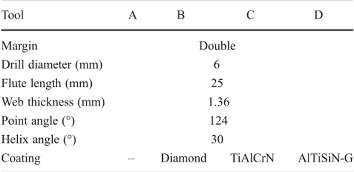
Coated and uncoated twist drills were used for drilling tests. All drills had the same geometry in terms of flute length (25 mm), point angle (124°) and helix angle (30°). The drill designated as tool A was uncoated and diamond, TiAlCrN and AlTiSiN-G coatings were used on tools B–D, respec-tively. Table1summarises drill geometry and coatings.
The stack sequence, CFRP on the top and metal on the bottom, was established with the industrial partner. This sequence generates less composite delamination as shown by Ramulu et al. [6]. Drilling experiments were performed on a 5-axis CNC horizontal machining center (Hera,
FATRONIK). The dynamometer (9257B, Kistler) was clamped on the machining table, and the workpiece was attached to an aluminium plate and bolted on the eter. The thrust forces were transmitted from the dynamom-eter to a signal amplifier (5019A, Kistler), then to a DAQ card (6062 E, NI) and recorded on a computer using Lab-View data acquisition software. Cutting conditions are sum-marised in Table2. Due to their dissimilar properties, CFRP and Al are two materials that have very different optimal machining settings. Despite this, the use of the Al optimal machining settings was recommended by the tool supplier. The drilling operations were carried out using a chip removing cycle. A micro-quantity lubrication system was used to provide a mist coolant throughout the operation with a constant flow rate of 16 mL/min. In the literature, the number of holes drilled to perform a study on tool wear during drilling CFRP/Al stacks rarely exceeds more than 100 holes. Tools tested in this study were used to drill 250 holes.
2.3 Analysis devices
After drilling tests, hole quality was investigated by mea-suring the diameter, the hole wall roughness and damages at the hole entrance. Diameters were measured in two levels in CFRP, at 1.5 mm from the hole entrance (H1) and at 1.5 mm from the exit (H2) but also at the mid-thickness of the aluminium (H3) plate. An inside micrometre was used for these measures (T&O, accuracy = 4 μm). The hole wall Table 1 Drill geometries and coatings
Tool A B C D Margin Double Drill diameter (mm) 6 Flute length (mm) 25 Web thickness (mm) 1.36 Point angle (°) 124 Helix angle (°) 30
Coating – Diamond TiAlCrN AlTiSiN-G
Table 2 Cutting conditions Cutting speed (m/min) Spindle speed (rpm) Feed (mm/rev) Feed rate (mm/min) 55 3,000 0.04 120
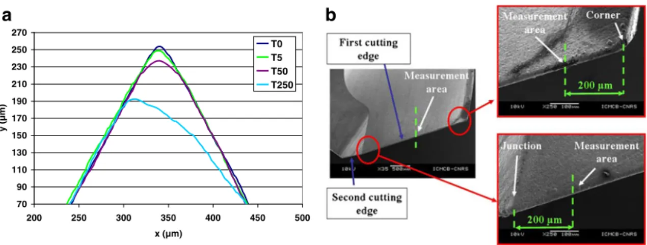
roughness was measured using a contact rugosimeter (MITUTOYO SURFTEST SV600). The hole entry dam-ages were investigated with a numerical microscope (VHX-1000, KEYENCE). The analysis software of this microscope has an algorithm (Depth from Defocus) that uses fine changes in texture to estimate height data. With the microscope software 3D tool edge geometry can be obtained. The 2D profile can then be extracted from the 3D model and used to measure cutting edge sharpness and the local wear quantity (LWQ). The latter is obtained by comparing the current profile of the cutting edge to the first one (of the unworn tool). An example can be seen in Fig.1awhere T0 designates the cutting edge profile of the unworn drill and T250 the profile after drilling 250 holes. This wear quantity is expressed by an area unit (in square micrometres). The analysis of 2D profiles also allows us to estimate flank wear and the cutting edge radius. These
measures were performed on three locations on the tool cutting edges: at 200 μm from the drill corner, at the centre and at 200 μm from the junction between the first and the second cutting edges, as seen in Fig. 1b. In addition, tool wear mechanisms were identified using a scanning electron microscope (SEM).
3 Results and discussion
3.1 Wear measurement and analysis of its evolution Flank wear VBis defined in the norm ISO 8688:1 as follows: “The flank wear is measured in a parallel direction to the wear facet and in a perpendicular direction to the initial cutting edge, for example from the initial cutting edge to the wear facet limit which cuts the initial flank face”. Gen-erally, using an electronic and/or an optical microscope, it is possible to measure the length between the current cutting
70 90 110 130 150 170 190 210 230 250 270 200 250 300 350 400 450 500 x (µm) y (µm) T0 T5 T50 T250
a
b
Fig. 1 a Cutting edge profile for tool A at 200μm from the drill corner after 5, 50 and 250 holes compared with the unworn profile (T0). b Measurement location on the cutting edge to obtain 2D edge profile
Fig. 2 Measurements of flank wear (VB) and local wear quantity (LWQ) on a cutting edge profile
0 500 1000 1500 2000 2500 3000 3500 4000 4500 5000 0 50 100 150 200 250 Hole number LWQ (µm²) Corner Center Point
Fig. 3 LWQ measured on three locations on the cutting edge 2113
edge and the last point worn on the flank face (VBSEM in Fig.2).
This type of measurement, done by Rawat et al. [11] to evaluate tool wear in drilling woven carbon fibre compo-sites, has shown a high sensibility of the wear on the rake face. As shown in Fig.2, the wear on the rake face has a direct impact on the value of VBSEM.If the wear on the rake face increases more rapidly than the wear on the flank face, a higher LWQ should be obtained but a smaller value of VBSEM. Consequently, this parameter (VBSEM) is not really suitable to describe the wear progression.
From the 2D cutting edge profiles, the actual flank wear value (VB in Fig.2) can be obtained. It is also possible to estimate, from the tool edge profiles superposition, the amount of the material locally lost by the tool (grey surface in Fig.2)
The measurement of the LWQ, on three locations on the cutting edge, has shown the non-proportionality of the LWQ with the radial position of the measurement location (Fig.3). The higher LWQ is found at the drill corner and it decreases up to the drill point.
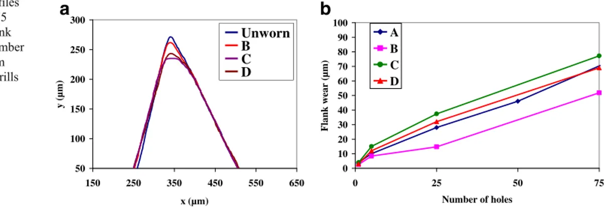
All the drills have the same unworn profile, except the cutting edge radius. Therefore, in Figs.4aand5a, only the
unworn profile of the drill A is shown. TiAlCrN (tool C) and AlTiSiN-G (tool D) coatings were not efficient. Their flank wear was very close to the one measured on the uncoated tool A (Fig. 4b). As shown in Fig. 4a, the cutting edge profiles of these tools are also similar.
Diamond coated tool B is the only really effective one. For this tool, the coating breakage occurred after drilling 150 holes. The flank wear measured on this coated drill is 50 % lower than that measured on the uncoated drill (tool A), as shown in Fig. 5b. As for the LWQ, the use of a diamond coating allows a drill wear decrease of about 80 %. 3.2 Wear mechanisms
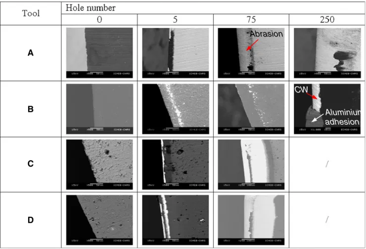
Figure6 shows the SEM images of the rake and the flank drill faces, beginning with the unworn stage (hole 0) up to hole 250. These images show that the drill cutting edge was mainly affected by abrasion wear, but some adhesion of Al can also be identified on the cutting edges. The abrasion was the main wear mechanism identified on the uncoated tool. Some adhesion can also be seen on the tool rake face but far from the cutting edge (tool A in Fig. 8). The coated drills underwent abrasion, followed by coating failure on the
a
b
50 100 150 200 250 300 150 250 350 450 550 650 x (µm) y (µm) 0 10 20 30 40 50 60 70 80 90 100 0 25 50 75 Number of holes Flank w ear (µm) A B C D Unworn B C DFig. 4 a Cutting edge profiles near the drill corner after 75 holes for drills B–D. b Flank wear evolution with the number of holes (located at 200μm from the drill corner) for drills A–D 0 50 100 150 200 250 300
a
150 250 350 450 550 650 x (µm) y (µm) 0 50 100 150 200 250 300 0 25 50 75 100 125 150 175 200 225 250 Number of holes Fla nk wear (µm) A B Unworn A Bb
Fig. 5 a Cutting edge profilesof unworn and worn A and B drills (after 250 holes). b Flank wear (near the drill corner) evolution with the number of holes
cutting edge and finally, adhesion wear. Zitoune et al. [12], on the contrary, found the aluminium adhesion as being the main wear mechanism when drilling CFRP/Aluminium stacks. Its results could be explained by the use of low cutting speeds (<38 m/min), which, as shown by List et al. [13] generates adhesion when machining soft materials such as Al.
As it can be seen on Fig. 6, the SEM images show the coating failure after the 5th hole, for tools C and D. The coating was removed all along the cutting edge. After drilling 75 holes, these tools can be considered as uncoated because extended areas on the flank and rake faces lost their coating. Therefore, the drilling tests were stopped after 75 holes.
CW
Aluminium
adhesion
Abrasion
A
B
C
D
Fig. 6 SEM images of drills flank faces
a
b
Al Al BUE CW Diamond coating CW Al BUE ToolFig. 7 a Attrition phenomenon on the cutting edges for tool B. b Zoom of the zone of interest, in chemical contrast
For uncoated tools, abrasion was observed on the chisel edge, on the corner, on the primary and on the second cutting edges. Before the coating failure, coated drill B underwent the same type of wear as the uncoated drill. It was subjected to abrasion, followed by coating failure on the cutting edge. After the coating failure, an aluminium layer replaced it on the cutting edge and created a build-up edge (BUE). This adhesive wear is then the site of WC attrition. The BUE, stuck on the cutting edge, tears CW particles when it is removed, as observed on Fig.7a, b.
Adhesion was also observed on the tool rake face. Grind-ing processes, carried out to prepare drill flutes, generate a relatively rough surface. Therefore, Al adheres on the rake face. The amount of Al deposited on the tool depends on the surface roughness. With a thin layer coating, like for tools C and D, the coating thickness was unable to totally erase the grinding marks (Fig.8). It can be observed that the coating takes the surface profile and the same amount of material adheres on the tool, as for the uncoated drill. The diamond coating thickness was able to“erase” the previous grinding marks (see tool B on Fig.8). Therefore, for this coating, less Al alloy has stuck on the rake face, as seen in Fig.8.
3.3 Thrust forces
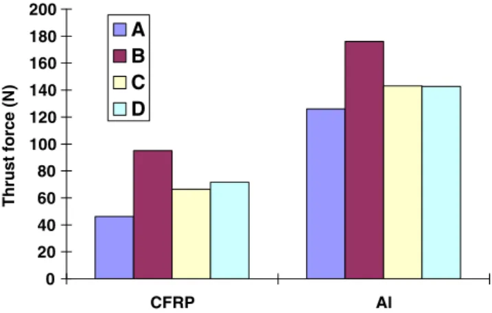
For the first hole, when the drills are unworn, the average thrust force of the uncoated drill A is from 30 to 50 % lower than the thrust forces of the coated drills B–D (Fig. 9), mainly due to the cutting edge sharpness. Cutting edge radius was 9μm for tool A, 11 μm for tools C and D, and 15 μm for tool B. This difference concerning the cutting edge sharpness is the consequence of the coating thickness.
The cutting edge radii of all the drills have the same value prior to being coated, between 6 and 9μm. With a thickness of 4–6 μm, the diamond coating is the thicker one and logically the higher cutting edge radius is observed for tool B. The same phenomenon was observed by Cheung [14] and Franke [15] in drilling steel and long fibre reinforced thermoplastics, respectively. In their study, the cutting edge radius varies from 7 to 42 μm and was obtained with a cutting edge preparation done by magneto-abrasive machin-ing or magnetic polishmachin-ing.
CFRP and Al have dissimilar mechanical properties. Therefore the thrust force generated by drilling has different magnitudes. As shown in Fig. 9, the force generated by CFRP drilling was lower than that produced in the alumin-ium, on the first hole. Zitoune et al. [12] obtained a similar trend, using comparable drill diameters. Brinksmeyer et al.
Grinding marks
A
B
C
D
Grinding marks
Al adhesion Al adhesion
Fig. 8 SEM images of rake faces of unworn and worn drills (after 75 holes)
0 20 40 60 80 100 120 140 160 180 200 CFRP Al Thrust fo rce (N) A B C D
[16] found opposite trends, higher thrust forces in CFRP than in Al, but the drill diameter was higher (16 mm).
The average thrust forces increase with the number of drilled holes (Fig.10a). The thrust forces generated by the uncoated drill, gradually rise in both CFRP and Al alloy. This trend was also observed for the coated drill B, but it was lower. This increase is mainly due to the tool wear. The thrust force grow is dissimilar between the two materials. For the aluminium, the increase of thrust force is asymptotic near the 250th hole while for the CFRP, the thrust force continues to increase. This implies that the thrust force measured in the CFRP can become higher than that ob-served in the aluminium, as for tool A on the 250th hole.
With a similar wear mechanism, tools A, C and D gen-erate similar flank wear. That induces the generation of similar force levels. This trend is also observed when one compares the thrust force generated by tools A and B when their LWQ is similar. Unlike tools A, C and D, which achieved an identical LWQ for the same number of holes, tools A and B reached a similar LWQ for a dissimilar number of holes: for the 35th hole for tool A and for the 250th hole for tool B. Their LWQ on the corner reaches 1,235 and 1,208 μm2, respectively, and the thrust forces generated by the drilling are similar in each material: 153 and 148 N in the CFRP and 218 and 203 N in the Al for tools A and B, respectively. This fact highlights the
a
b
0 100 200 300 400 0 50 100 150 200 250 Number of hole Thrust force (N ) A B C D CFRP AlFig. 10 a Evolution of average thrust force with the number of holes. b Thrust force signal on hole No. 200 (for one of the five cutting passages in Al plate)
a
b
c
d
5,950 5,955 5,960 5,965 5,970 5,975 5,980 5,985 5,990 5,995 6,000 0 50 100 150 200 250 Hole number Ø (mm) 5,950 5,955 5,960 5,965 5,970 5,975 5,980 5,985 5,990 5,995 6,000 0 50 100 150 200 250 Hole number Ø ( m m) 5,950 5,955 5,960 5,965 5,970 5,975 5,980 5,985 5,990 5,995 6,000 0 50 100 150 200 250 Hole number Ø (mm) 5,950 5,955 5,960 5,965 5,970 5,975 5,980 5,985 5,990 5,995 6,000 0 50 100 150 200 250 Hole number Ø (mm) H1 H2 H3 H1 H2 H3 H1 H2 H3 H1 H2 H3Fig. 11 Hole diameter evolution for tool a A, b B, c C
influence of the drill micro-geometry and therefore, of the wear on the thrust force.
After the diamond coating breakage (tool B after 150 holes), the average thrust force in the aluminium plate shows almost an asymptotic evolution. This trend could be explained by: (1) a material softening due to high temperatures or (2) an auto-optimisation of the tool geometry. As shown in Fig. 10, the thrust force does not decrease during the Al drilling. Therefore, no metal softening was observed.
The benefit of the diamond coating on thrust force is shown in Fig.10. For the same cutting conditions, the use of a diamond coating can decrease the force (by limiting wear) by 65 % when drilling CFRP and by 35 % in Al. 3.4 Hole quality
Hole quality was investigated by measuring hole diameters, CFRP damage and hole wall surface roughness.
3.4.1 Hole diameter
Figure11a–dshows that the evolution of the diameter of the holes with the number of drilled holes is relatively stable, especially for tools A and B. This stability was also ob-served by Benezech et al. [17]. It can also be seen that the diameter of the holes drilled in CFRP (H1 and H2 in Fig.11) is bigger than the one measured in the Al alloy. Some additional experiments have shown that opposite trends can be obtained following the used cutting condition and particularly, the lubrication condition. Without lubrication and for the same tool geometry, the diameter of the holes drilled in CFRP remains the same but bigger diameters are produced in the aluminium. Therefore, diameters of the holes drilled in Al are becoming bigger than those produced in the CFRP. This difference can be due to thermal phenom-ena that occur during the drilling process. A diameter dif-ference in CFRP and in the metal part was also noted by Shyha et al. [18].
The difference between the average diameter in both altitudes in CFRP, and the diameter in metal, noted ΔØ, is shown in Fig.12. Best results are observed for drills A and B with a ΔØ of 8 to 9 μm against 16 to 18 μm for drills C and D. As it can be seen in Figs.11and 12, the presence of a coating has little or no influence on the diameter difference (ΔØ). No diameter deviation was observed with the number of holes, as it can be seen in Fig. 11. With a similar drill diameter, different results were obtained by Benezech et al. [17] where the diam-eter difference was nearly 30 μm.
3.4.2 CFRP damage
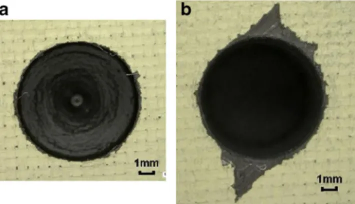
The CFRP damage at the hole entrance, shown in Fig.13b, was observed whatever the drill used, starting with the first hole. Therefore, it can be concluded that this phenomenon is not due to the tool wear. It can be caused by the tool geometry, as described by Hocheng et al. [19], where the drill flute pulls out the first layers of the composite material. Or, in the case of a multi-material, this damage can be due to the metallic chip evacuation through the hole, as observed by Brinksmeier et al. [8]. The last hypothesis has been proved in our case by observations made before aluminium part drilling and chip evacuation. Due to the chip removing cycle, the drilling process can be stopped at any time. For ten holes, the drilling process was stopped before creating aluminium chips. A workpiece photo was taken at this moment and no CFRP damage was observed, as it can be seen in Fig.13a. After completed drilling process, the CFRP damage reaches more than 2 mm (Fig.13b). The drill flute does not guide the chip
0 5 10 15 20 25 0 50 100 150 200 250 Hole number Δ Ø (µ m) A B C D
Fig. 12 ΔØ evolution with the number of drilled holes
Fig. 13 CFRP damages at the hole entry a before and b after alumin-ium chip evacuation
enough all along its length and, as seen by a CCD high speed camera, the metal chip is in contact with the hole entrance. As shown in Fig.13b, this damage is not localised all around the hole entrance. It is situated in places where the direction of the chip movement (due to drill rotation) and the fibre orientation creates a−45° angle. In this configuration, similar damages have been observed by Iliescu [20] during CFRP cutting.
3.5 Hole wall roughness
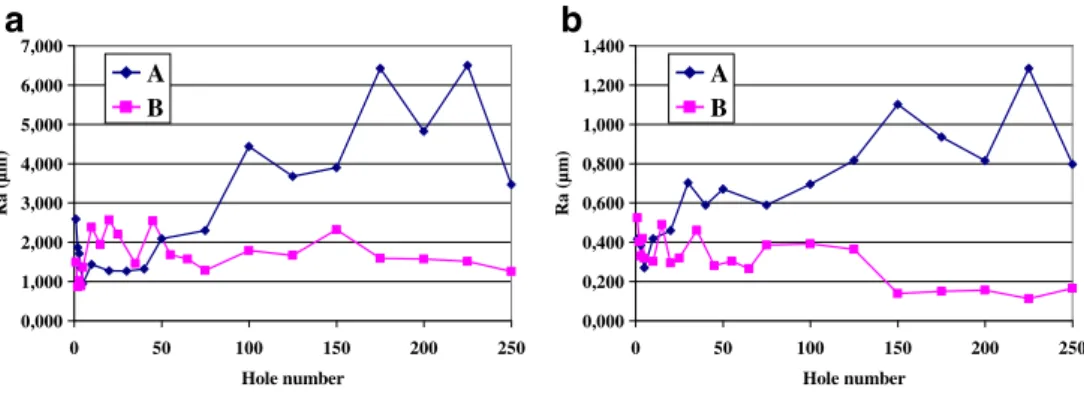
As it can be seen in Fig.14, the hole wall roughness on the first 50 drillings was similar for uncoated (A) and coated (B) tools. The same roughness level was found by Zitoune et al. [12] in their study on the influence of machining parameters on drilling performance of CFRP/aluminium stacks.
The roughness of the holes performed by the uncoated tool (A) increases with the number of drilled holes, in both materials (Fig.14a, b). This phenomenon is greatly problematic, because the roughness can become higher than the one required in the aeronautics industry. Currently, the maximum acceptable roughness in aeronautics is 1.6μm in Al and 3.2 μm in CFRP. In the Al, the roughness increase is slight and remains at an acceptable level. In the CFRP part, the uncoated tool produces hole wall roughnesses higher than 3.2μm, after 75 drilled holes.
The increasing of the roughness is due to the wear undergone by tool A and its rapid growth. Sharp cutting edges generate no defect on the holes wall (Fig. 15a) and low roughness is measured. When the tool cutting edge sharpness becomes too low, the drill is unable to cut the carbon fibres. These fibres are rather pulled out than cut, especially when the cutting direction and the fibres create a −45° angle. As a consequence, little cavities are generated on the holes wall (Fig.15b) and therefore, the roughness increases. The same phenomenon was observed by Iliescu [20] when drilling CFRP plates.
Low hole surface roughness with a good stability in time (Fig. 14) is obtained by diamond coated tool B, due to its slight evolution of the cutting edge profile (Fig.5a).
4 Conclusions
Cutting forces, holes quality and tool wear analysis on coated and uncoated carbide drills were analysed for the drilling of CFRP/Al stacks.
Two types of wear were highlighted above: abrasive and adhesive wear. Abrasion was the strongest wear mechanism observed in CFRP/Al drilling, due to the highly abrasive carbon fibres. 0,000 1,000 2,000 3,000 4,000 5,000 6,000 7,000 0 50 100 150 200 250 Hole number
a
b
Ra ( µ m ) 0,000 0,200 0,400 0,600 0,800 1,000 1,200 1,400 0 50 100 150 200 250 Hole number Ra ( µm) A B A BFig. 14 Roughness Ra for the a CFRP part and b Al part
Fig. 15 CFRP hole wall on the a 1st and b 250th hole drilled by the uncoated tool A
The results have shown that, as the number of drilled holes increases, the thrust forces generated by both coated and uncoated drills gradually increase in both CFRP and Al parts, mainly due to the tool wear.
The study has also highlighted the influence of the evo-lution of the drill micro-geometry (and therefore, of the tool wear) on the thrust force.
Lower flank wear and thrust forces and, therefore, good hole quality were obtained when using the diamond coating. The study has shown that the CFRP damage at the hole entry is due to the aluminium chips evacuation and it is not, in our case, due to the tool geometry.
References
1. Batzer SA, Haan DM, Rao PD, Olson WW, Sutherland JW (1998) Chip morphology and hole surface texture in the drilling of cast aluminum alloys. J Mater Process Technol 79(1–3):72–78 2. Nouari M, List G, Girot F, Géhin D (2005) Effect of machining
parameters and coating on wear mechanisms in dry drilling of aluminium alloys. Int J Mach Tool Manuf 45(12–13):1436–1442 3. Lachaud F, Piquet R, Collombet F, Surcin L (2001) Drilling of
composite structures. Compos Struct 52(3–4):511–516
4. Hocheng H, Tsao CC (2003) Comprehensive analysis of delami-nation in drilling of composite materials with various drill bits. J Mater Process Technol 140(1–3):335–339
5. Iliescu D, Gehin D, Gutierrez ME, Girot F (2010) Modeling and tool wear in drilling of CFRP. Int J Mach Tool Manuf 50(2):204–213 6. Ramulu M, Branson T, Kim D (2001) A study on the drilling of
composite and titanium stacks. Compos Struct 54(1):67–77 7. Park KH, Beal A, Kim D, Kwon P, Lantrip J (2011) Tool wear in
drilling of composite/titanium stacks using carbide and polycrys-talline diamond tools. Wear 271(11–12):2826–2835
8. Brinksmeier E, Janssen R (2002) Drilling of Multi-layer composite materials consisting of carbon fiber reinforced plastics (CFRP),
titanium and aluminum alloys. CIRP Ann Manuf Technol 51(1):87–90
9. Zitoune R, Krishnaraj V, Collombet F (2010) Study of drilling of composite material and aluminium stack. Compos Struct 92(5):1246–1255
10. Rawat S, Attia H (2009) Characterization of the dry high speed drilling process of woven composites using Machinability Maps approach. CIRP Ann Manuf Technol 58(1):105–108
11. Rawat S, Attia H (2009) Wear mechanisms and tool life manage-ment of WC–Co drills during dry high speed drilling of woven carbon fibre composites. Wear 267(5–8):1022–1030
12. Zitoune R, Krishnaraj V, Almabouacif BS, Collombet F, Sima M, Jolin A (2012) Influence of machining parameters and new nano-coated tool on drilling performance of CFRP/Aluminium sand-wich. Compos Part B: Eng 43(3):1480–1488
13. List G, Nouari M, Géhin D, Gomez S, Manaud JP, Le Petitcorps Y, Girot F (2005) Wear behaviour of cemented carbide tools in dry machining of aluminium alloy. Wear 259(7–12):1177– 1189
14. Cheung FY, Zhou ZF, Geddam A, Li KY (2008) Cutting edge preparation using magnetic polishing and its influence on the performance of high-speed steel drills. J Mater Process Technol 208(1–3):196–204
15. Franke V (2011) Drilling of long fiber reinforced thermoplastics— influence of the cutting edge on the machining results. CIRP Ann Manuf Technol 60(1):65–68
16. Brinksmeier E, Fangmann S, Rentsch R (2011) Drilling of compo-sites and resulting surface integrity. CIRP Ann Manuf Technol 60(1):57–60
17. Benezech L, Landon Y, Rubio W (2012) Study of manufacturing defects and tool geometry optimisation for multi-material stack drilling. Adv Mater Res 423:1–11
18. Shyha IS, Soo SL, Aspinwall DK, Bradley S, Perry R, Harden P, Dawson S (2011) Hole quality assessment following drilling of metallic-composite stacks. Int J Mach Tool Manuf 51(7–8):569– 578
19. Ho-Cheng H, Dharan CKH (1990) Delamination during drilling in composite laminates. Trans ASME J Eng Ind 112:236–239 20. Iliescu D (2009) Approche expérimentale et numérique de
l’usin-age des composites carbone/epoxy. Thesis of the Ecole Nationale Supérieure des Arts et Métiers