Science Arts & Métiers (SAM)
is an open access repository that collects the work of Arts et Métiers Institute of
Technology researchers and makes it freely available over the web where possible.
This is an author-deposited version published in: https://sam.ensam.eu
Handle ID: .http://hdl.handle.net/10985/12999
To cite this version :
Hussein ZAHR, Franck SCUILLER, Eric SEMAIL - Five-phase SPM machine with electronic pole changing effect for marine propulsion - In: 2016 International Conference on Electrical Systems for Aircraft, Railway, Ship Propulsion and Road Vehicles & International Transportation
Electrification Conference (ESARS-ITEC), France, 2016-11 - Five-phase SPM machine with electronic pole changing effect for marine propulsion - 2016
Any correspondence concerning this service should be sent to the repository
Five-phase SPM machine with electronic pole
changing effect for marine propulsion
Hussein Zahr
Laboratory of Electrical Engineering and Power Electronics of Lille (L2EP)
Lille - FRANCE [email protected]
Franck Scuiller
Naval Academy Research Institute IRENav
Brest - FRANCE [email protected]
Eric Semail
Laboratory of Electrical Engineering and Power Electronics of Lille (L2EP)
Lille - FRANCE [email protected]
Abstract—In this paper, the possibility of designing a
five-phase Surface-mounted Permanent Magnet (SPM) machine with 20 slots and 8 poles for a low power marine propulsion system is examined. Due to its particular winding and surface magnet design, the machine inherently offers an electronic pole changing effect from 3×4 pole pairs at low speed to 4 pole pairs at high speed. At high speed, in the constant power range, according to Finite Element Analysis, the Maximum Torque Per Ampere strategy appears not to be the right solution to minimize the whole machine losses (copper, iron and magnets). In particular, a strategy that favors the 4-pole rotating field at high speed allows to mitigate the magnet losses, thus limiting the risk of magnet overheating.
I. NOMENCLATURE
SPM Surface-mounted Permanent Magnet
FEA Finite Elements Analysis
CPR Constant Power Range
MM Main Machine (1st harmonic dq-subspace)
SM Secondary Machine (3rd harmonic dq-subspace)
Ω𝑚 Mechanical speed (rad/s)
𝑝 Pole pair number
𝑅 Armature resistance
𝜖1,𝜖3 MM and SM no load back-emf at 1 rad/s
𝐿1,𝐿3 MM and SM cyclic inductances
𝜃1,𝜃3 MM and SM back-emf to current angles
𝐼1,𝐼3 MM and SM currents
𝑉𝑏,𝐼𝑏 Base RMS voltage and current
Ω𝑏,𝑇𝑏 Base speed and torque
II. INTRODUCTION
Multi-phase motors are widely used in electrical marine propulsion for reasons such as reliability, smooth torque and distribution of power [1]. For low power propulsion system (less than 10kW), the power partition constraint results from the low DC voltage (less than 60V) that supplies the drive. Hence increasing the phase number allows to limit the rating of the power electronic components. In addition, compact-ness objective can be more easily achieved if the phase number is considered as a design parameter. For instance, with five-phase machine, third harmonic current injection can be performed to boost the torque [2], [3]. Regarding the rotor, Permanent Magnet (PM) structure contribute to enhance the power density [4], [5]. In case of Surface-mounted Permanent Magnet (SPM) rotor, the ripple torque
mitigation is facilitated. Furthermore, with five-phase SPM machine, third harmonic current injection can be used to eliminate the pulsating torque [6]. If fractional-slot windings facilitate the reduction of cogging torque for SPM machine [7], they also generate magnetomotive force harmonics that could result in excessive magnet losses. Machine with 0.5
slots per phase and per pole (𝑠𝑝𝑝 = 0.5) are known to
limit this effect [8]. In addition, the slot filling can also be improved with this solution [9]. Therefore the machine here considered is a five-phase machine with 20 slots and 8 poles (20-8-5 configuration) for a marine propeller.
The 3-phase counterpart of this 20-8-5 machine has 8 poles and 12 slots (12-8-3 configuration). With reference to this 12-8-3 machine, the benefits of the 20-8-5 machine are examined in [10] for the same design specifications: rated torque, power and external diameters are identical. With numerical computations of the two machines, this study shows that the 5-phase configuration allows a significant reduction of the magnet losses. In addition, the 5-phase ma-chine facilitates the reduction of the ripple torques (cogging and pulsating) that is of critical importance at low speed.
This paper focuses on another property of the 20-8-5 machine. Due to its particular winding distribution, this
machine inherently owns 3×4 pairs of pole and 4 pairs
of pole. Hence an electronic pole changing effect can be obtained if the machine is designed to operate at low speed
with 3×4 pole pairs or at high speed with 4 pole pairs. More
generally the appropriate polarity has to be selected regarding the load demand in transient or steady state, taking into account the inverter rating and the efficiency or torque quality requirements. Pole changing methods by winding switching are well known for induction machine [11]. For multiphase induction machine, pole phase modulation strategy can be applied [12]. In [13], the speed range of a five-phase PM machine is extended by switching between different stator configurations. A similar procedure is achieved in [14] but with electronic switching. In this paper, the pole changing effect is electronically ensured by the inverter, depending of the levels of first and third harmonics of current.
The paper is divided into two parts. In the first part, the 20-8-5 machine design is introduced. The magnet layer to obtain the double polarity property is introduced. To master
the sizing, numerical field calculations are reported and the torque/speed characteristic is estimated. The second part focuses on the control strategy in the constant power range that corresponds to the steady state operation of the propeller. Two strategies are described and compared regarding the copper, magnet and iron losses (estimated with FEA).
III. MACHINE DESIGN
A. Five-phase machine modeling
If the magnetic saturation and the demagnetization issue are not considered, it can be shown that a star-connected five-phase SPM machine behaves as two two-phase virtual machines that are magnetically independent but electrically and mechanically coupled [15]. Furthermore, as the rotor saliency can be neglected with SPM machines, the space harmonics are distributed among the two virtual machines: the virtual machine sensitive to the fundamental is called Main Machine (MM) whereas the other sensitive to the third harmonic is called Secondary Machine (SM). Actually the virtual machine is a physical reading of the mathematical subspace build on the linear application that describes the phase-to-phase magnetic couplings: this two-dimension
sub-space is usually represented with𝛼𝛽-axis circuit in stationary
frame or with𝑑𝑞-axis circuit in rotating frame. As there is no
saliency effect, no distinction has to be made between d-axis and q-axis inductance.
B. Design specifications
The machine is intended to be integrated in a pod for an electrical outboard. The propeller is driven by the electrical machine with a mechanical gear that reduces the electrical rotating speed by five. The main machine parameters are listed in table I.
TABLE I
PARAMETERS FOR THE CONSIDERED MACHINE
Rated Em power 𝑃𝑒𝑚= 7.7𝑘𝑊
Constant Speed Range [2250𝑟𝑝𝑚 − 4500𝑟𝑝𝑚]
Rated Em Torque 𝑇𝑒𝑚,𝑟= 34.0𝑁𝑚
DC voltage 𝑉𝑑𝑐= 30𝑉
Base current 𝐼𝑏= 290𝐴
Pole pair number 𝑝 = 4
Slot number per phase per pole 𝑠𝑝𝑝= 0.5
Effective length 𝐿𝑚= 0.0923𝑚
External diameter 𝐷𝑒𝑥𝑡= 0.209𝑚
Stator diameter 2𝑅𝑠= 0.1444𝑚
Stator yoke thickness 𝑡𝑦𝑠= 0.011𝑚
Mechanical airgap 𝑔 = 0.001𝑚
Rotor yoke thickness 𝑡𝑦𝑟= 0.011𝑚
Magnet layer thickness ℎ𝑚= 3𝑔
Remanent flux density 𝐵𝑟= 1.17𝑇
Slot width (𝜏𝑠, tooth pitch) 0.5𝜏𝑠
Slot width opening 0.25𝜏𝑠
Slot-closing thickness 𝑡𝑠𝑐= 0.001𝑚
Slot depth 𝑑𝑠= 0.0205𝑚
Linear load 𝐴𝐿= 25.6 × 10³𝐴/𝑚
Current density 𝑗𝑠= 5 × 10⁶𝐴/𝑚2
The electromagnetic circuit is sketched out in Fig.1 (over a pole pair): the five-phase winding distribution with the
corresponding first and third harmonic winding factors (𝑘𝑤,1
and 𝑘𝑤,3) can be observed. The magnet layer shape is
arranged to make the two virtual machines enable to produce the same torque level. To reach this goal, the rotor pole consists of two radially magnetized magnets, each magnet covering one third of the pole arc, as illustrated by Fig.1.
Winding Factor k
w,1=0.5878
k
w,3=0.9811
Fig. 1. Electromagnetic circuit of the 5-phase machine
C. Field analysis
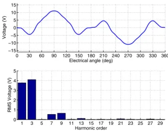
In this subsection, the electromagnetic behaviour of the machine is estimated with FEA software FEMM [16] under magnetostatic hypothesis. In addition, saturation effects are not taken into account (linear assumption for the materials). Fig.2 shows the no-load back-emf waveform and spec-trum. The double polarity of the machine can be inferred. The spectrum confirms that first and third harmonic terms are of the same order.
0 30 60 90 120 150 180 210 240 270 300 330 360 −15 −10 −5 0 5 10 15
Electrical angle (deg)
Voltage (V) 1 3 5 7 9 11 13 15 17 19 21 23 25 27 29 0 1 2 3 4 5 Harmonic order RMS Voltage (V)
Fig. 2. No load back-emf at 2250rpm mechanical speed (FEA)
The inductance values𝐿1for the MM and𝐿3for the SM
are calculated by loading the machine with the rated current:
∙ 𝐿1= 3.1𝑚𝐻 for the MM (4 pole pairs)
∙ 𝐿3= 4.0𝑚𝐻 for the SM (3 × 4 pole pairs).
Fig.3 shows the flux lines when loading the machine with fundamental rated current (for a given rotor position). The
field intensity values allow to control the right sizing of the electromagnetic circuit: in the yokes and in the stator teeth, the field intensity is lower than 1.4T. Fig.4 focuses on the cogging torque estimation. As previous, the cogging torque is negligible: its amplitude is less than 0.25Nm, that is less than 1% the rated torque.
Density Plot: |B|, Tesla 1.900e+000 : >2.000e+000 1.800e+000 : 1.900e+000 1.700e+000 : 1.800e+000 1.600e+000 : 1.700e+000 1.500e+000 : 1.600e+000 1.400e+000 : 1.500e+000 1.300e+000 : 1.400e+000 1.200e+000 : 1.300e+000 1.100e+000 : 1.200e+000 1.000e+000 : 1.100e+000 9.000e-001 : 1.000e+000 8.000e-001 : 9.000e-001 7.000e-001 : 8.000e-001 6.000e-001 : 7.000e-001 5.000e-001 : 6.000e-001 4.000e-001 : 5.000e-001 3.000e-001 : 4.000e-001 2.000e-001 : 3.000e-001 1.000e-001 : 2.000e-001 <0.000e+000 : 1.000e-001
Fig. 3. Flux density (for fundamental rated current)
0 5 10 15 20 25 30 35 40 45 −0.25 −0.2 −0.15 −0.1 −0.05 0 0.05 0.1 0.15 0.2 0.25
Mechanical Angle (deg)
Cogging torque (Nm)
Fig. 4. Cogging torque estimation (FEA)
D. Maximum reachable torque for finite Volt-Ampere rating
In this subsection, the torque/speed characteristic of the
machine is calculated: for a given mechanical speedΩ𝑚(i.e.
for a given electrical speed𝜔), taking into account the
max-imum DC voltage and the maxmax-imum copper losses (driven
by base current𝐼𝑏), the goal consists in finding the MM and
SM current distribution that maximizes the electromagnetic torque [17]. To solve this problem is equivalent to find the optimal d-axis and q-axis references for each virtual machine. The Maximum Torque Per Ampere (MTPA) for a given speed is then obtained. The optimization variable is defined as follows:
𝑧 =[ 𝐼1 𝜃1 𝐼3 𝜃3 ]𝑇 (1)
The optimization variable is lower and upper bounded ac-cording to the following relations:
𝑍𝑙𝑜𝑤 = ⎡ ⎢ ⎢ ⎣ 0 −𝜋 0 −𝜋 ⎤ ⎥ ⎥ ⎦ ≤ 𝑧 ≤ ⎡ ⎢ ⎢ ⎣ 𝐼𝑏 𝜋 𝐼𝑏 𝜋 ⎤ ⎥ ⎥ ⎦ = 𝑍𝑢𝑝 (2)
The objective is to maximize the electromagnetic torque. This
goal is expressed in the following relation where 𝑇 is the
average electromagnetic torque:
𝑧∗= 𝑎𝑟𝑔𝑚𝑖𝑛(−𝑇 (𝑧)) (3)
The average electromagnetic torque is the sum of the torque of each virtual machine. The MM torque (due to the
funda-mental of current) is denoted 𝑇1 and the SM torque (due to
the third harmonic of current) is denoted 𝑇3:
𝑇1= 5𝜖1𝐼1cos 𝜃1 (4)
𝑇3= 5𝜖3𝐼3cos 𝜃3 (5)
The five-phase machine torque is then expressed as follows:
𝑇 = 5𝜖1𝐼1cos 𝜃1+ 5𝜖3𝐼3cos 𝜃3 (6) Equation (6) is used in relation (3) to track the optimal current
repartition 𝑧∗. The non linear constraint regarding the peak
phase voltage is written in the following relation:
𝑓𝑉(𝑧) = max {𝑣(𝑝Ω𝑚𝑡, 𝑧), 𝑝Ω𝑚𝑡 ∈ [0..2𝜋]} − 𝑉𝑝𝑒𝑎𝑘 (7)
In equation (7), 𝑣(𝑝Ω𝑚𝑡, 𝑧) is the machine phase-to-neutral
voltage for the current determined by 𝑧 at Ω𝑚 speed. It
should be noted that the considered voltage contains all the harmonics (i.e. not only the first and the third harmonics). The maximum allowable peak voltage is chosen to be half the bus voltage (thus meaning that linear modulation operation is targeted):
𝑉𝑝𝑒𝑎𝑘= 𝑉2𝑑𝑐 (8)
The constraint relative to the maximum RMS current is defined by the following equation:
𝑓𝐼(𝑧) = 𝑧(1)2+ 𝑧(3)2− 𝐼𝑏2 (9)
The following expression summarizes the optimization prob-lem under consideration:
𝑧∗ = 𝑎𝑟𝑔𝑚𝑖𝑛(−𝑇 (𝑧)) with ⎧ ⎨ ⎩ 𝑍𝑙𝑜𝑤 ≤ 𝑧 ≤ 𝑍𝑢𝑝 𝑓𝑉(𝑧) ≤ 0 𝑓𝐼(𝑧) ≤ 0 (10)
Fig.5 shows the resulting torque/speed characteristic cor-responding to the resolution of optimization problem (10). It can be observed that the rated torque (about 34Nm) is obtained by using the virtual MM and the virtual SM in the same time, thus meaning that the five-phase machine here considered is designed to operate with first and third harmonic of current. In addition, the electronic pole changing
effect is obtained since, at low speed, the MM (3 × 4
speed, the SM (4 poles) torque becomes higher. The iso-power line (7.7kW) drawn in fig.5 allows to determine the constant power range that is between 2250rpm and 4500rpm (as specified in table I).
0 1000 2000 3000 4000 5000 6000 0 5 10 15 20 25 30 35 Speed (rpm) Torque (Nm) Iso−power (7.7kW) Main Machine Secondary Machine Both
Fig. 5. Maximum reachable torque for the five-phase machine
IV. CONTROL STRATEGIES IN THECONSTANTPOWER
RANGE
This section focuses on the machine operation in the CPR. At low speed (below 2250rpm), the machine is supposed being in transient states and the MTPA strategy previously in-troduced is performed. At high speeds (between 2250rpm and 4500rpm), the constant power control is used: in this mode, since the torque is not maximized, the constant power can be obtained with different current distributions, depending on the considered objective. Therefore, two objectives will be examined: one that aims to reduce the copper losses and another that aims to maximize the MM torque contribution. These two strategies will be compared regarding the machine losses with FEA.
A. Constant Power Control with minimizing copper losses
For the control here described, the goal consists in minimizing the copper losses for a given electromagnetic power accounting the maximum allowable peak voltage. For a given torque, as the copper losses are minimized, this strategy is actually a MTPA one and is called CPR-MTPA in the following. The optimization problem can be written as follows: 𝑧∗ = 𝑎𝑟𝑔𝑚𝑖𝑛(𝑧(1)2+ 𝑧(3)2) with ⎧ ⎨ ⎩ 𝑍𝑙𝑜𝑤≤ 𝑧 ≤ 𝑍𝑢𝑝 𝑓𝑉(𝑧) ≤ 0 𝑓𝑇(𝑧) = 0 (11)
In relation (11), 𝑓𝑇(𝑧) is the constraint relative to the
torque, simply obtained by dividing the required constant
electromagnetic power𝑃𝑒𝑚 by mechanical speedΩ𝑚:
𝑓𝑇(𝑧) = 𝑇 (𝑧) −𝑃Ω𝑒𝑚
𝑚 (12)
The speeds where the CPR can be achieved are deduced from the maximum torque/speed characteristic estimated in the previous subsection (2250rpm - 4500rpm).
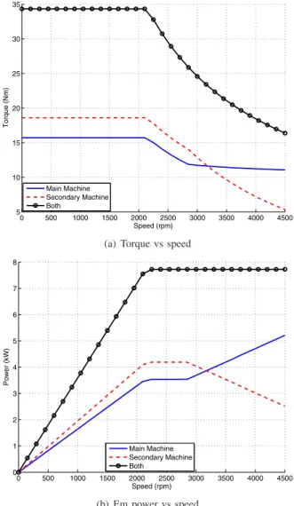
Fig.6a shows the obtained torque/speed characteristics: at low speed (below 2250rpm), the reported characteristic is the one according to the MTPA strategy (10) whereas, at high speed, the reported characteristic is the one corresponding to the resolution of the CPR problem (11) introduced in this subsection. Again the torque repartition between the two virtual machines confirms the electronic pole changing effect: at low speed, the SM is mainly used whereas, at high speed, the MM becomes predominant. Fig.6b gives the corresponding power/speed characteristics. As specified, the CPR is actually obtained between 2250rpm and 4500rpm and the electronic pole changing effect already observed when, looking at Fig.6a, is confirmed.
0 500 1000 1500 2000 2500 3000 3500 4000 4500 5 10 15 20 25 30 35 Speed (rpm) Torque (Nm) Main Machine Secondary Machine Both
(a) Torque vs speed
0 500 1000 1500 2000 2500 3000 3500 4000 4500 0 1 2 3 4 5 6 7 8 Speed (rpm) Power (kW) Main Machine Secondary Machine Both (b) Em power vs speed
Fig. 6. Torque and power with CPR-MTPA strategy
B. Constant Power Control with favoring Main Machine
In order to reinforce the pole changing effect at high speed, the constant power control (between 2250rpm and
4500rpm) is calculated so that the Main Machine torque contribution is maximized (always accounting the maximum allowable peak voltage). With this strategy, a limitation of the magnet eddy current losses is expected because the Main Machine owns 0.5 slot per pole and per phase [8]. This strategy is called CPR-h1 and is obtained by solving the following optimization problem:
𝑧∗ = 𝑎𝑟𝑔𝑚𝑖𝑛(−𝑇1(𝑧)) with ⎧ ⎨ ⎩ 𝑍𝑙𝑜𝑤 ≤ 𝑧 ≤ 𝑍𝑢𝑝 𝑓𝑉(𝑧) ≤ 0 𝑓𝑇(𝑧) = 0 (13)
In (13),𝑇1denotes the torque produced by the Main Machine
defined by (4).
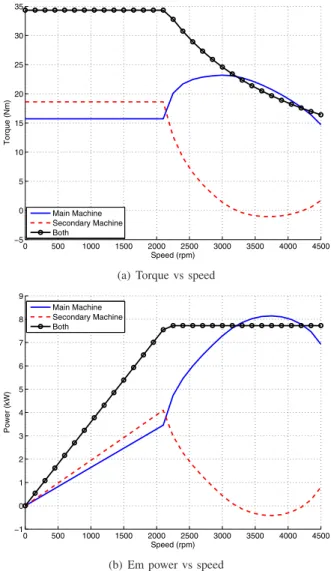
Fig.7a and Fig.7b show respectively the resulting torque/speed and power/speed characteristics when solving optimization problem (13) at high speed (at low speed, below 2250rpm, the MTPA characteristic is given). As aimed for, the torque produced by the Main Machine is maximized in the Constant Power Range. One can observe that, between 3200 and 4200rpm, the Secondary Machine operates in gen-erator mode to facilitate the Main Machine power increase.
C. Losses analysis
Copper, magnet and iron (stator and rotor) losses are now considered with FE software Ansys Maxwell. Magnet and iron losses are estimated from the time variation of the flux density. The method to calculate the hysteresis, eddy current and excess losses is close to the one detailed in [18]. For speed belonging to the CPR, the five-phase machine is simulated for the optimized currents corresponding to the CPR-MTPA and CPR-h1 strategies.
Fig.8a and Fig.8b give the copper, magnet and iron losses according to the speed for the MTPA and the CPR-h1 strategies respectively. With the CPR-MTPA strategy, as aimed for, the copper losses are minimized but, in Fig.8a, it can be observed that copper losses do not represent the major losses. This trend is all the truer as the speed increases. Referring to the CPR-MTPA strategy that allows the lowest copper losses, the CPR-h1 strategy allows to reduce the whole losses up to 3200rpm as shown by Fig.8b. This advantage is based on the significant decrease of the magnet losses. This result complies with the analysis carried out in [10] where it is shown that the asynchronous space harmonics due the third harmonic generate eddy currents in the magnet layer. For SPM machine, magnet losses mitigation is critical because the magnet layer can not be cooled as easily as the stator winding. In steady state, the magnet losses should be carefully controlled to prevent from demagnetization due to overheating.
Fig.9 gives another insight of the possible losses reduction with the CPR-h1 strategy: the efficiency versus speed for the two strategies are represented. Thus the efficiency enhance-ment up to 3200rpm with the CPR-h1 strategy is illustrated. Finally, for the SPM 20-8-5 machine, the MTPA strategy is
0 500 1000 1500 2000 2500 3000 3500 4000 4500 −5 0 5 10 15 20 25 30 35 Speed (rpm) Torque (Nm) Main Machine Secondary Machine Both
(a) Torque vs speed
0 500 1000 1500 2000 2500 3000 3500 4000 4500 −1 0 1 2 3 4 5 6 7 8 9 Speed (rpm) Power (kW) Main Machine Secondary Machine Both (b) Em power vs speed
Fig. 7. Torque and power with CPR-h1 strategy
not the right solution to maximize the efficiency and to limit the heating of the magnets.
V. CONCLUSION
In this paper, the estimations of the 20-8-5 machine performances are obtained without considering magnetic saturation and demagnetization issue. With a particular but quite simple design of the magnet layer, the 20-8-5 machine
inherently owns 3×4 pole pairs and 4 pole pairs. With
a single stator and single rotor structure, a magnetic gear behavior is then obtained by controlling two rotating fields. The torque/speed characteristic calculated by considering the current and voltage limitations imposed by the inverter confirms the electronic pole changing effect: at low speed, the
SM (3×4 poles) mainly contributes to the torque whereas, at
high speed, the MM (4 poles) torque becomes higher. As the propeller is specified to operate in the constant power range at steady state (between 2250rpm and 4500rpm), the ma-chine losses are numerically estimated for two CPR control strategies: the CPR-MTPA that minimizes the copper losses and the CPR-h1 that favors the MM torque contribution.
22500 2500 2750 3000 3250 3500 3750 4000 4250 4500 100 200 300 400 500 600 700 800 900 1000 1100 Speed (rpm) Losses (W) Copper Iron Magnets Sum
(a) With CPR-MTPA strategy (11)
22500 2500 2750 3000 3250 3500 3750 4000 4250 4500 100 200 300 400 500 600 700 800 900 1000 1100 Speed (rpm) Losses (W) Copper Iron Magnets Sum (b) With CPR-h1 strategy (13)
Fig. 8. Losses according to the speed in the CPR
2250 2500 2750 3000 3250 3500 3750 4000 4250 4500 0.85 0.86 0.87 0.88 0.89 0.9 0.91 0.92 0.93 0.94 0.95
Constant Power Range
Speed (rpm)
Efficiency
CPR−MTPA (minimizing copper losses) CPR−h1 (maximizing MM torque)
Fig. 9. Efficiency in the CPR for the two strategies
A better efficiency is obtained with CPR-h1 control up to 3200rpm, with a significant reduction of the magnet losses for the whole speed range. Finally, for the 20-8-5 machine here considered, the existence of an optimal Maximum Torque Per Losses (MTPL) strategy is then demonstrated and have to be explored in further studies.
REFERENCES
[1] E. Levi, “Multiphase electric machines for variable-speed applications,” Industrial Electronics, IEEE Transactions on, vol. 55, no. 5, pp. 1893– 1909, 2008.
[2] E. Semail, X. Kestelyn, and A. Bouscayrol, “Right harmonic spectrum for the back-electromotive force of an n-phase synchronous motor,” in Industry Applications Conference, 2004. 39th IAS Annual Meeting. Conference Record of the 2004 IEEE, vol. 1, Oct 2004, p. 78. [3] K. Wang, Z. Zhu, and G. Ombach, “Torque improvement of
five-phase surface-mounted permanent magnet machine using third-order harmonic,” Energy Conversion, IEEE Transactions on, vol. 29, no. 3, pp. 735–747, Sept 2014.
[4] “Oceanvolt website,” http://oceanvolt.com, accessed: 2016-29-09. [5] “Torqeedo website,” http://www.torqeedo.com, accessed: 2016-29-09. [6] F. Scuiller, “Third harmonic current injection to reduce the pulsating
torque of a five-phase spm machine,” in Industrial Electronics Society, IECON 2015 - 41st Annual Conference of the IEEE, Nov 2015, pp. 000 811–000 816.
[7] Z. Q. Zhu and D. Howe, “Influence of design parameters on cogging torque in permanent magnet machines,” IEEE Transactions on Energy Conversion, vol. 15, no. 4, pp. 407–412, December 2000.
[8] B. Aslan, E. Semail, and J. Legranger, “General analytical model of magnet average eddy-current volume losses for comparison of multi-phase pm machines with concentrated winding,” Energy Conversion, IEEE Transactions on, vol. 29, no. 1, pp. 72–83, March 2014. [9] A. M. EL-Refaie, “Fractional-slot concentrated-windings synchronous
permanent magnet machines: Opportunities and challenges,” IEEE Transactions on Industrial Electronics, vol. 57, no. 1, pp. 107–121, Jan 2010.
[10] H. Zahr, E. Semail, and F. Scuiller, “Five-phase version of 12slots/8poles three-phase synchronous machine for marine-propulsion,” in Vehicle Power and Propulsion Conference (VPPC), 2014 IEEE, Oct 2014, pp. 1–6.
[11] M. Osama and T. A. Lipo, “A new inverter control scheme for induction motor drives requiring wide speed range,” IEEE Transactions on Industry Applications, vol. 32, no. 4, pp. 938–944, Jul 1996. [12] A. Gautam and J. O. Ojo, “Variable speed multiphase induction
machine using pole phase modulation principle,” in IECON 2012 -38th Annual Conference on IEEE Industrial Electronics Society, Oct 2012, pp. 3659–3665.
[13] S. Sadeghi, L. Guo, H. A. Toliyat, and L. Parsa, “Wide operational speed range of five-phase permanent magnet machines by using dif-ferent stator winding configurations,” IEEE Transactions on Industrial Electronics, vol. 59, no. 6, pp. 2621–2631, June 2012.
[14] N. K. Nguyen, E. Semail, F. Meinguet, P. Sandulescu, X. Kestelyn, and B. Aslan, “Different virtual stator winding configurations of open-end winding five-phase pm machines for wide speed range without flux weakening operation,” in Power Electronics and Applications (EPE), 2013 15th European Conference on, Sept 2013, pp. 1–8.
[15] E. Semail, A. Bouscayrol, and J.-P. Hautier, “Vectorial formalism for analysis and design of polyphase synchronous machines,” Eur. Phys. J., vol. AP 22, pp. 207–220, 2003.
[16] D. Meeker, “Finite element method magnetics, version 4.2, users manual,” FEMM official website, October 2010.
[17] F. Scuiller, H. Zahr, and E. Semail, “Maximum reachable torque, power and speed for five-phase spm machine with low armature reaction,” IEEE Transactions on Energy Conversion, vol. 31, no. 3, pp. 959– 969, Sept 2016.
[18] D. Lin, P. Zhou, W. N. Fu, Z. Badics, and Z. J. Cendes, “A dynamic core loss model for soft ferromagnetic and power ferrite materials in transient finite element analysis,” IEEE Transactions on Magnetics, vol. 40, no. 2, pp. 1318–1321, March 2004.