HAL Id: in2p3-00362477
http://hal.in2p3.fr/in2p3-00362477
Submitted on 18 Feb 2009HAL is a multi-disciplinary open access
archive for the deposit and dissemination of sci-entific research documents, whether they are pub-lished or not. The documents may come from teaching and research institutions in France or abroad, or from public or private research centers.
L’archive ouverte pluridisciplinaire HAL, est destinée au dépôt et à la diffusion de documents scientifiques de niveau recherche, publiés ou non, émanant des établissements d’enseignement et de recherche français ou étrangers, des laboratoires publics ou privés.
New Methods for HTR Fuel Waste Management
Fabrice Guittonneau, Abdesselam Abdelouas, Bernd Grambow, Manoel
Dialinas, François Cellier
To cite this version:
Fabrice Guittonneau, Abdesselam Abdelouas, Bernd Grambow, Manoel Dialinas, François Cellier. New Methods for HTR Fuel Waste Management. 4th International Topical Meeting on High Temper-ature Reactor Technology, Sep 2008, Washington, United States. �in2p3-00362477�
NEW METHODS FOR HTR FUEL WASTE MANAGEMENT
Fabrice Guittonneau, Abdesselam Abdelouas, Bernd Grambow, Manoël Dialinas
SUBATECH, UMR 6457, 4 Rue Alfred Kastler, 44307 Nantes Cedex 3, France
François Cellier
AREVA NP, 10 rue Juliette Récamier, 69456 Lyon Cedex 06, France
ABSTRACT
Considering the need to reduce waste production and greenhouse emissions by still keeping high energy efficiency, various 4th generation nuclear energy systems have been proposed. As far as graphite moderated reactors are concerned, one of the key issues is the large volumes of irradiated graphite encountered (1770 m3 for fuel elements and 840 m3 for reflector elements during the lifetime (60 years) of a single reactor module [1]). With the objective to reduce volume of waste in the HTR concept, it is very important to be able to separate the fuel from low level activity graphite. This requires to separate TRISO particles from the graphite matrix with the sine qua non condition to not break TRISO particles in case of future embedding of particles in a matrix for disposal.
According to National Regulatory Systems, in case of limited graphite waste production or of short duration HTR projects (e.g. in Germany), direct disposal without separation is acceptable. Nevertheless, in case of large scale deployment of HTR technology, such approach is not economical and sustainable. Previous attempts in graphite management (furnace, fluidised bed and laser incinerations and encapsulation matrices) dealt with graphite matrix only. These are the reasons why we studied the management of irradiated compact-type fuel element. We simulated the presence of fuel in the particles by using ZrO2 kernels. Compacts with ZrO2 TRISO particles were manufactured by AREVA NP.
Two original methods have been studied. First, we tested high pressure jet to erode graphite and clean TRISO particles. Best erosion rate reached about 0.18 kg/h for a single nose ending. Examination of treated graphite showed a mixture of undamaged TRISO particles, particles that have lost the outer pyrolytic carbon layer and ZrO2 kernels. Secondly, we studied the thermal shock method by immerging successively graphite into liquid nitrogen and hot water to cause fracturing of the compact. This produced particles and graphite fragments with diameter ranging from several centimetres to less than 500 µm. This relatively simple and economic method may potentially be considered as a pre-treatment step and be coupled with other method(s) before reprocessing and recycling for example.
1. INTRODUCTION
One of the main objectives considering the nuclear waste management, particularly for the 4th generation of reactors, is to reduce the waste volume. Main HTR High Level Wastes (HLW) including fission products and actinides are contained in TRISO particles while graphite can be considered as Low Level Waste (LLW). In case of large scale deployment of the HTR technology, it becomes obvious to separate TRISO particles (HLW) from the graphite matrix (LLW) of the compacts or pebbles. This separation has to keep intact TRISO particles to avoid graphite contamination with HLW. In this paper we present two new methods for TRISO particles separation from graphite. Hence, we tested (1) the high pressure water jet method and (2) the thermal shock method using three different media: liquid nitrogen, hot water and an air furnace.
2. PART A: HIGH PRESSURE JET 2.1. Technique presentation
High pressure water jet technique was initiated by Norman Franz in the late 1960’s and has been employed for the industry for the first time in the 70’s by Alton Boxboard for the plywood cutting [2]. The method principle consists to project water at very high speed (several hundred of meter per second) in continuous jet by a nozzle of small diameter (several hundred of microns). The water pressure in the system can reach 4200 bar due to hydraulic pumps and pressure multiplier. The jet energy allows extracting matter at relatively low temperature compared to lasers. This jet can cut very various materials like steels, concrete, plastic, glass, ceramic, wood, carpet, leather, food… For harder materials, the cutting power can be improved by adding
2.2. Experimental procedure
The main problem to solve for testing such technique is to control the fixation of graphite compact and to avoid the loss of TRISO particles. For this, we used a stainless steel filter of cylindrical shape in which the compact with TRISO particles was inserted. Internal diameter of the filter was a little bigger (~14 mm) than the compact one (~12.5 mm). Its 500 µm mesh permitted to only keep TRISO particles inside (~900 µm) and to evacuate graphite particles.
Because of the heavy equipment used for these experiments, we performed our experiments at the industrial partner site,
CRITT Techniques Jet Fluides et Usinage, at Bar-Le-Duc, France. The high pressure system can deliver 100 horse power at
4000 bar but here, we limited the pressure to 1670 bar at the end of the nozzle to prevent breaking of TRISO particles. For our tests, we used a five-axes-head robot. The carbide-made nozzle had two diametrical nicks to obtain a flat jet. In our case, the water flow Q (L/min) is formulated by
P
Q=0.46×ϕ²× (1)
where φ the nozzle diameter (0.7 mm) and P the water pressure (1670 bar), and matched up to 9.2 L/min. The pump power (in kW) is calculated via κ × × 600 P Q (2)
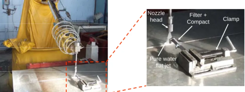
where κ is the yield (near 0.8), and reached about 32 kW. Robot and detail of the nozzle are represented on figure 1. During the different tests, the water jet runs back and forth at about 3 cm above the filter with a parallel or perpendicular direction.
Nozzle
head CompactFilter +
Pure water flat jet
Clamp
Figure 1: Five-axes-head robot and detail of the nozzle head
2.3. Results – Discussion
Several tests were conducted and parameters were adjusted during testing because of the lack of literature data on graphite erosion. A preliminary test was performed with an arbitrary pressure of about 500 bar on a compact containing 9.9 % of TRISO particles. The filter-mesh mark visible on the compact surface was conclusive. Thus, we increased up the pressure to 1670 bar to be more efficient.
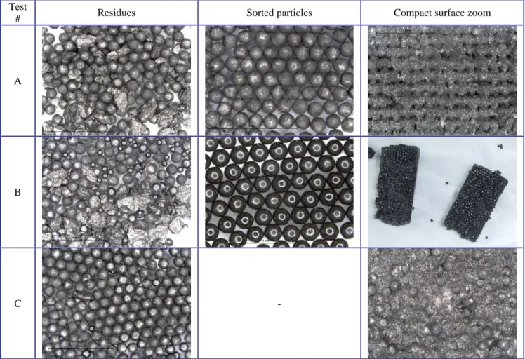
Table 1 summarizes results of different tests and table 2 shows photographs corresponding to treated graphite and TRISO particles.
Table 1: Summary of water jet tests on compacts Test # Jet orienta-tion* TRISO Vol% Total
TRISO Intact TRISO
Damaged TRISO** TRISO without coating*** Effective duration of the test Lost graphite Graphite erosion rate (%/min) A Perpendicular 9.9 400 394 (98.5%) 6 (1.5%) 0 (0%) 120 s 31.1% 15.6 B Parallel 9.9 521 237 (45.5%) 48 (9.2%) 236 (45.3%) 165 s 50.1% 18.2 C Perpendicular 20.9 1662 1425 (85.7%) 140 (8.4%) 97 (5.8%) 114 s 69.3% 36.5
(*) perpendicular orientation indicates that the jet is perpendicular to the filter/compact system but its displacement is parallel to it. (**) oPyC layer is cracked or missing.
Table 2: Photographs of compacts and TRISO particles after water jet tests presented in table 1 Test
# Residues Sorted particles Compact surface zoom
A
B
C -
The results show that the experimental parameters determine the quality of the final product. Test A does not contain any cracked TRISO particles and only shows a few which have lost their outer pyrolytic carbon layer. Sorted particles are clean and free of the graphite matrix. The small mass loss rate (~16 %/min) compared to the test C can be attributed to the distance nozzle head – steel filter, which is difficult to control in this kind of test and which is not indicated in the table. The highest quantity of graphite (90.1 % compared to 79.1 %) could not play a role important enough in this erosion rate ratio. In the case of test B, it is obvious that parameters are not adequate because a large TRISO particles proportion is broken, as seen on the general view and sorted particles. Each black sphere is the ZrO2 kernel of 500 µm diameter, lightened by the LED circle from microscope. The parallel orientation with the perpendicular jet displacement seems to not be the good choice because the erosion only occurs on a little compact area. Results from test C are quite optimal; the erosion of one compact (36.5 %/min) corresponds to a graphite mass loss of about 0.12 kg/h and a total mass loss of about 0.18 kg/h. Compared to incineration techniques (several kilograms per hour [12]), it can appear to be weak but the system could easily be multiplied. The 6 % fraction of fractured TRISO is certainly due to the distance between the jet and the filter and/or the large amount of enclosed particles. Indeed, it is possible that TRISO bumped into each others and against the filter at very high speed and provoked their coating failure.
Although optimization of the high pressure jet is still needed to obtain better results, this original process has to be kept in mind for erosion application using a fluid like water or liquid nitrogen, as proposed in general conclusion.
3. PART B: THERMAL SHOCK METHOD 3.1. Historical review – Experimental procedure
Classic thermal shock theory was established in the 60’s by Hasselman. The material resistance R is usually given by the formula
( )
ν σThermal shocks are often made using lasers, electric arcs, plasmas or electrons beams in case of passage from room temperature to a warm medium whereas in the case of quenching experiments on brittle materials [18] water is often used as cooling liquid.
Graphites are materials which have good behavior during brutal temperature change, due to their high thermal conductivity (about 100 W.m-1.K-1) and their weak thermal expansion coefficient (usually between 4 and 6.10-6 K-1). Considering these properties, we tested the resistance of compacts submitted to rapid transfers from hot to cold media (from air furnace to liquid nitrogen) and from cold to hot media (from liquid nitrogen to hot water) by taking advantage of their porosity. We see from the expression of R that with small Young’s modulus and small coefficient of thermal expansion, nuclear graphite resistance should be high compared to the one of ceramics which usually display high value of these two properties.
3.2. Results – Discussion
A compact containing 10 % of TRISO particles was placed in an alumina crucible in a furnace during 15 min at 777 K and was transfered into a Dewar filled with liquid nitrogen (77 K). No apparent damage was visible despite ΔT = -700 K. Three other cycles were performed without any visible crack. This result shows the exceptional behavior of compacts with respect to thermal quenching. We did not increase the temperature difference ΔT because of the graphite oxidation by air above about 810 K as shown in the thermogravimetric analysis (TGA) in figure 2.
-35 -30 -25 -20 -15 -10 -5 0 300 400 500 600 700 800 900 1000 1100 1200 1300 Temperature (K) M ass Loss (%) Graphite Zr TRISO
Figure 2: Graphite and Zr-TRISO TGAs (heat rate: 1 K/min)
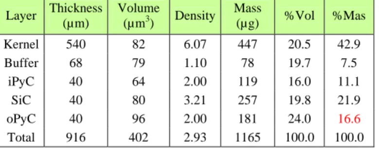
Also, TRISO particles, composed of zirconium oxide kernels, seem a little more sensitive than graphite and oxidize in the same conditions at about 770 K. The total mass loss (16.7 %) corresponds only to the outer pyrolytic carbon layer oxidation (see table 3). Silicon carbide layer is not subject to the oxidation at these temperatures.
Table 3: Details of volume and mass layers fractions in one Zr-TRISO measured and calculated from SEM images and pycnometry analyses Layer Thickness (µm) Volume (µm3) Density Mass (µg) %Vol %Mas Kernel 540 82 6.07 447 20.5 42.9 Buffer 68 79 1.10 78 19.7 7.5 iPyC 40 64 2.00 119 16.0 11.1 SiC 40 80 3.21 257 19.8 21.9 oPyC 40 96 2.00 181 24.0 16.6 Total 916 402 2.93 1165 100.0 100.0
The TGA results and data in table 3 clearly show that a thermal treatment of a compact will oxidize all graphite and oPyC on a large range of temperature, from about 800 K up to the temperature of SiC oxidation by air. Moreover, the oxidation resistance of SiC was verified during the oxidation in air of an entire compact containing a packing fraction (PF) of 10 % of TRISO particles at 1100 K. Nearly 1400 particles were recovered and their SiC coatings were all undamaged, as seen on figure 3. Graphite oxidation (dried path or acid path) can be coupled with the capture of CO2 by bubbling gases into alkaline or lime solutions to precipitate carbonates.
Figure 3: Photograph of SiC surface TRISO after compact oxidation at 1100K during 16 h
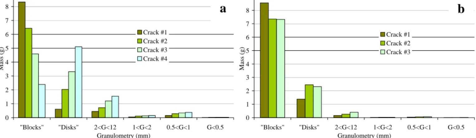
The second experiment was made by operating from cold medium (liquid nitrogen) to warm medium (water at about 360 K). We used two particle loads (10 % and 20 %). Compacts were immerged into a Dewar filled of liquid nitrogen for several minutes and then put into a beaker containing hot water. After cracking, all the graphite pieces were recovered, dried, sieved and weighted. A few cycles were required to breach the compacts. The size distribution of the broken graphite is given in figures 4a and 4b for 10% and 20% PF, respectively. The designation ‘Disks’ refers to pieces with a disk shape (between 2 and 5 mm height) and the designation ‘Blocks’ refers to pieces which have a height larger than 5 mm, usually between 10 and 30 mm.
Compact with 10 % PF cracked every two cycles whereas those with 20 % PF cracked every three cycles. During one cycle of the 20 % PF, fragments number and mass are less important than for 10% PF. Free TRISO particles are contained in the fraction 0.5<G<1. They are all undamaged. Other particles are bonded to the graphite matrix in bigger granulometry ranges. The presence of fragments with a disk shape indicates that the force generated inside the compact is mainly directed in the direction of its axis.
The weak temperature difference (ΔT ≈ 280 K) can’t explain itself the crack of the material. It seems likely that liquid nitrogen enters into graphite pores and quickly evaporates when the compact is put into hot water. This evaporation is very strong and the resulting internal pressure seems to be responsible of the crack. Better results could be obtained if oxygen from air present into the pores could be substituted by nitrogen.
This method allows to divide roughly and randomly a compact into smaller fragments but is not suitable to separate all TRISO particles from the graphite. This division leads to increase the surface of the compact in preparation for another treatment.
0 1 2 3 4 5 6 7 8 "Blocks" "Disks" 2<G<12 1<G<2 0.5<G<1 G<0.5 Granulometry (mm) Mass (g) Crack #1 Crack #2 Crack #3 Crack #4 0 1 2 3 4 5 6 7 8 "Blocks" "Disks" 2<G<12 1<G<2 0.5<G<1 G<0.5 Granulometry (mm) Mass (g) Crack #1 Crack #2 Crack #3
Figure 4: Total mass fraction distribution of compact fragments after each thermal shock cycle (a: compact at 10 % and b: compact at 20 %)
4. GENERAL CONCLUSION
These original experiments on nuclear graphite compacts give some new ideas and increase the panel of potential choice in the field of nuclear waste management. Concerning the high pressure water jet, we can summarize as follow:
• Using liquid nitrogen may help to obtain better results than with water according to recent CRITT work [19]. As well as the high pressure of the jet the thaw of the fluid increases the efficiency of graphite separation. Moreover, no effluent would be present due to the natural recycle of nitrogen in the atmosphere.
The high pressure jet method is much more efficient than the thermal shock one for graphite separation. The main reason is the incomplete separation between particles and graphite, giving blocks of several centimeters and disks of several millimeters in height after each crack. However, the thermal shock method could be used as a first pre-treatment to prepare graphite blocks for final treatment.
5. REFERENCES
[1] D. Grenèche, W. J. Szymczak, Nuclear Engineering and Design, 236, 635, (2006). [2] CRITT,
http://www.critt-tjfu.com/rubrique.php3?id_rubrique=16.
[3] A. H. Osman, T. Mabrouki, B. Théry, and D. Buisine, Flow Measurement and Instrumentation, 15, 37 (2004). [4] L. Cui, L. An, and W. Gong, International Journal of Mineral Processing, 81, 113 (2006).
[5] L. Cui, L. An, W. Gong, and H. Jiang, Fuel, 86, 750 (2007).
[6] C. W. Guo and L. Dong, Journal of China University of Mining and Technology 17, 251 (2007). [7] Z. Sun, X. Q. Kang, and X. H. Wang, Materials & Design, 26, 59 (2005).
[8] T. Momma and A. Lichtarowicz, Wear, 186-187, 425 (1995). [9] S. Hattori, Y. Goto, and T. Fukuyama, Wear, 260, 1217 (2006).
[10] Q. Fang, H. Xu, P. S. Sidky, and M. G. Hocking, Wear, 224, 183 (1999).
[11] B. J. Briscoe, M. J. Pickles, K. S. Julian, and M. J. Adams, Wear, 203-204, 88 (1997).
[12] IAEA, Characterization, treatment and conditioning of radioactive graphite from decommissioning of nuclear reactors (IAEA, Vienna, 2006-09), IAEA-TECDOC-1521.
[13] D. P. H. Hasselman, American Ceramic Society Bulletin 49, 1033 (1970).
[14] Z. Yang, D. Jia, Y. Zhou, Q. Meng, P. Shi, and C. Song, Materials Chemistry and Physics, 107, 476 (2008). [15] R. Shi, Y. Yin, J. Li, and D. Wang, Materials Research Bulletin, In Press, Corrected Proof.
[16] J. H. Kim, Y. S. Lee, D. H. Kim, N. S. Park, J. Suh, J. O. Kim, and S. Il Moon, Materials Science and Engineering A,
387-389, 385 (2004).
[17] C. Tian, N. Liu, and M. Lu, International Journal of Refractory Metals and Hard Materials, 26, 478 (2008). [18] M. Collin and D. Rowcliffe, Acta Materialia, 48, 1655 (2000).