HAL Id: hal-01716273
https://hal.archives-ouvertes.fr/hal-01716273
Submitted on 8 Nov 2018
HAL is a multi-disciplinary open access
archive for the deposit and dissemination of
sci-entific research documents, whether they are
pub-lished or not. The documents may come from
teaching and research institutions in France or
abroad, or from public or private research centers.
L’archive ouverte pluridisciplinaire HAL, est
destinée au dépôt et à la diffusion de documents
scientifiques de niveau recherche, publiés ou non,
émanant des établissements d’enseignement et de
recherche français ou étrangers, des laboratoires
publics ou privés.
Evaluation of viscous and elastic parameters of a
borosilicate glass above transition temperature using
optical instrumented squeeze tests
Gilles Dusserre, Gérard Bernhart, Fabrice Schmidt, Gilles Dour
To cite this version:
Gilles Dusserre, Gérard Bernhart, Fabrice Schmidt, Gilles Dour. Evaluation of viscous and elastic
parameters of a borosilicate glass above transition temperature using optical instrumented squeeze
tests.
Journal of Non-Newtonian Fluid Mechanics, Elsevier, 2011, 166 (21-22), pp.1229-1238.
Evaluation of viscous and elastic parameters of a borosilicate glass above
transition temperature using optical instrumented squeeze tests
G. Dusserre
⇑, G. Bernhart, F.M. Schmidt, G. Dour
Université de Toulouse, Mines Albi, ICA (Institut Clément Ader), Campus Jarlard, F-81013 Albi cedex 09, France
Keywords: Borosilicate glass Optical measurement Squeeze test Rheometry Viscosity Elasticity
a b s t r a c t
Oxide glasses viscosity exhibits a large temperature dependence from viscous fluid to fully hard solid, requiring several complementary experimental methods to measure this parameter over the wide tem-perature range involved during forming. As a matter of fact, the accuracy of any glass forming process simulation depends on these data. This paper mainly focuses on the development of an analytical method that allows to extend the validity of the cylinder compression test (squeeze flow) over higher tempera-tures, using experimental data from an optical contactless instrumentation. The accuracy of the method is discussed by comparing the results to the bibliographical data concerning the studied borosilicate glass rheology. The method provides a full field strain and strain rate tensors evaluation and also allows to monitor the test and especially contact conditions between the sample and the compression plates even for intermediate strains. A numerical modeling of the experiment shows that identified elastic and vis-cous parameters allow a proper agreement with experiment even for large strains.
1. Introduction
Pyrex!borosilicate glass is widely used to produce dishes and
other items for cookware or chemical applications because of its high resistance to chemicals and to thermal stresses. Glass hollow parts are formed by squeezing a glass gob between two molds[1]. These molds are often made of stainless steels and are subjected to mechanical loading by the shaping of the gob and to thermal stres-ses by cooling the glass from 1300"C down to temperatures lower than its glass transition temperature (598"C[2]).
During the forming process, the glass viscosity increases dra-matically from 102to 1010Pa!s due to the high temperature
depen-dence of viscosity[2] in the temperature range involved in the process (1350–650"C[3]). In order to obtain reliable results using numerical simulation, accurate knowledge of glass thermo-mechanical behavior over a large temperature, strain and strain rate range is then required. In order to accurately model the pro-cess, it is further necessary to conduct a fundamental study of the behavior of the glass in conditions close to those involved in the actual glass pressing process, i.e. not only with shear test, but also in elongation condition.
Glass cylinder compression tests are used to perform equibiax-ial elongation viscosity measurements[4,5]of glasses at
interme-diate temperatures from 108 to 1012Pa!s [2]. Biaxial elongation
without shear is achieved uniformly if there is perfect slip at the plates and otherwise only in the symmetry plane. Other tests are based on shear viscosity measurement by rotation methods such as cone and plate rheometer or Couette rheometer in the lower vis-cosity ranges: 104–106Pa!s[6]for the former two and 1–104Pa!s
[7]for the latter. Finally fiber elongation method[8,9]is best suited from 106to 1011Pa!s[10]and to measure high elongation viscosity
of glass under high strain rate.
The literature provides some Pyrex!viscosity values (Fig. 1)
ob-tained by compression tests performed between 620 and 680"C
(1011.85–108.79Pa!s[2]), by Couette rheometry performed between
900 and 1520"C (105.11–101.63Pa!s [2]) and by fiber elongation
method performed between 545 and 645"C (1013.6–1010.9Pa!s
[9]). The temperature range from 680 to 900"C (105–108Pa!s),
above glass transition and within the forming temperature range, has not yet been investigated by these usual methods. Glass viscos-ity is indeed too high to be measured by rotation methods, but low enough to allow the sample to creep under its own weight while heating before squeezing, hence making squeeze test performing difficult.
This lack of data is usually fulfilled by fitting the experimental data with mathematical models to evaluate the viscosity values over the whole temperature range involved in the process. The empirical Vogel–Tammann–Fulcher equation [11] is the most widely used in the simulation of glass forming processes[12–14]. The Adam Gibbs theory[15]which considers the configurational entropy to describe the temperature dependence of glasses ⇑ Corresponding author. Tel.: +33 (0)5 63 49 33 09; fax: +33 (0)5 63 49 32 42.
E-mail address:gilles.dusserre@mines-albi.fr(G. Dusserre).
viscosity is more commonly used by physicists, for example to study geological melts[16,17].
Squeeze test is widely used to measure high viscosities by pressing a cylindrical sample between two parallel plates. The lit-erature provides a large number of experimental and theoretical works related to this method and its application to rheometry
[18]. It is particularly well suited to perform characterization of viscoplastic materials [19]or yield-stress fluids such as suspen-sions of spheres [20] or fibers[21] often modeled by Bingham law[22]. Many test conditions are available[18](constant force or speed rate, constant squeezed section or volume, various aspect ratios) and experiments are performed easily. Moreover analytical solutions exist for viscous fluid behavior (Newtonian or power law viscosity[18]) currently assumed for glass rheology while forming at high temperature. At intermediate temperature elasticity mani-fests itself and the method is then a very useful tool to study glass creeping flow, relevant for forming simulation. Nevertheless the modeling of the test depends strongly on boundary conditions and especially on sample-plates contact conditions which are not uniform in the contact area.
This paper details a squeeze test improved by contactless opti-cal instrumentation and an associated analytiopti-cal method, both aiming at enlarging the range of the glass rheology measurement using compression test up to 900"C and with larger strains than usual. The local analytical modeling proposed does not necessitate to model sample-plates contact condition to evaluate the viscosity (calculation of strain field at the maximal radius plane). The viscos-ity data obtained are used to validate the existing fitting models over their whole range of validity. The data accessed optically also provide information about the contact conditions (sticking, perfect slip). Numerical simulations of the tests are performed to validate elastic and viscous parameters values obtained by comparison with the experiment.
2. Experimental procedure 2.1. Material and sample preparation
The investigated material is a borosilicate glass designed for cookware applications (resistant to thermal stresses thanks to an expansion coefficient lower than 3.10"6K"1up to 300"C) known
under its commercial designation Pyrex!. The composition of very
similar borosilicate glasses is available in the literature as given in
Table 1 [2,23–25]. According to Sipp et al.[2], its glass transition temperature is 598"C, relevant with data by Ota et al. [24], depending on sample heat treatment.
The tested cylindrical samples dimensions are 30 mm diameter and 20 mm height. They were machined in a 22 mm thick plate using a diamond hole saw with water cooling and lubrication. The two flat faces were grinded parallel. Height/diameter ratio about 2 is usually chosen in literature in order to reduce the con-tact area with the compression plates and then minimize the
friction contribution[4]. In the present case, the friction is not ne-glected and the sample is subjected to creep under gravitational ef-fect while heating up to testing temperature, and an aspect ratio of 2/3 was chosen to minimize its variation while creeping. The resulting residual stresses are neglected afterwards.
2.2. Experimental setup and optical measurements
Cylinder compression tests are performed with a 50 kN MTS 810 servohydraulic universal testing machine. The samples are squeezed at constant crosshead displacement rate between two polished compression plates made out of alumina and lubricated with boron nitride to avoid sample sticking on the plates [26]. The setup is heated in a resistive furnace as shown inFig. 2. Com-pression load and crosshead displacement are measured by the way of the testing machine acquisition setup (50 kN MTS 661.20F-62 load cell). According to the stiffness of the setup, about 177 kN!mm"1, and the maximal load applied, lower than 25 kN,
the relative error on the effective sample deformation using the crosshead displacement is lower than 1.5%.
The test temperature ranges from 650 to 900"C, and the cross-head displacement rate from 0.0833 to 2 mm!s"1. At high
temper-ature, the crosshead displacement has to be fast enough to overcome the creep under gravity of the specimen. Stresses, strains and strain rates are deduced from measured loads, displacements and displacement rates and are reported inTable 2. Stresses lower than 20 MPa have been applied, involving no shear thinning effect according to Sipp et al.[2].
500 700 900 1100 1300 1500
Fiber elongation [2] Compression [2] Couette [9]
°C Forming temperature range
Pyrex®viscosity (log Pa.s)
14 10 8 6 4 2
Investigated range
Fig. 1. Temperature range of the different set of bibliographical data[2,9].
Table 1
Chemical composition of Pyrex!borosilicate glasses[2,8,9,23–25].
Oxides mol.% [23] wt.% [2] wt.% [8,9,25] wt.% [24] SiO2 82.57 81.10 81.00 80.00 B2O3 10.81 12.30 12.60 13.00 Al2O3 1.23 2.05 2.40 2.25 Na2O 5.13 5.20 3.90 3.50 K2O 0.13 0.20 – 1.15 CaO 0.05 0.05 – – MgO 0.05 0.03 – – TiO2 0.02 0.02 – – FeO 0.01 0.01 – 0.05
The mechanical measurements are completed by a contactless instrumentation consisting of a 8-bit Qimaging!Qicam CCD digital
camera (resolution: 1360 # 1024 pixels, lens: Nikkor Nikon 50 mm f1.8) and a computer performs the data logging at a maximum rate of 10 Hz. Image processing provides the coordinates of any point on the sample external surface while squeezing. Typical magnifica-tion factors are 22.2 pixels/mm. The origin of the optical measure-ment is the top plate that remains fixed during the test. The samples surface does not exhibit any texture at high temperature, and it is therefore very difficult to track with the camera several points independently. Consequently it is impossible to follow the trajectory of a material point located on the profile of the sample as it is currently done at room temperature[27]. The Lagrangian description of the profile is then impossible to monitor, conse-quently the Eulerian description of the radius of the sample is used in Section3. The procedure used to extract the data from the image acquisition is described in next section.
2.3. Image processing procedure
The exact dimensions of the sample at room temperature being known, a first image is acquired before any preheating of the sam-ple to calibrate the magnification factor from the mean values of sample diameter and height. The apparent diameter measured in pixel on the picture is related to the exact diameter of the sample but is not exactly the same. The relative error in neglecting this projection effect is lower than 0.12%. The corresponding bias is lower than 0.035 mm, which is smaller than the pixel size.
The sample profile is extracted using the image processing soft-ware, Gimp!(Fig. 3). The diameters are measured in a direction
parallel to the upper plate and the heights are measured perpen-dicularly. The coordinates of six points of the profile are measured, including the sample/plates contact points. The diameter measure-ment resolution, corresponding to the thickness of the extracted profile, is of two pixels (about 0.09 mm) thanks to an optimization
of the contrast between sample profile and background. The sam-ple height measurement is less accurate because of the weak depth of field, the perspective effect and a bad contrast between sample and compression plates.
3. Analytical modeling of squeeze test 3.1. Usual method
Viscosities measured by compression tests are usually deduced with the assumption that the friction between the sample and the compression plates is negligible [28–30]. For example, this is achieved with alumina plates covered with a 50
l
m thick platinum foils[4]. The strain rate is evaluated from the height of the sample measured with a LVDT sensor, and the stress is the ratio between the applied load and the sample section, supposed to remain cylin-drical after deformation (small strains). The viscosity is estimated by the ratio between stress and strain rate as derived from Newto-nian fluid equation in a one-dimensional case.However compression tests implies a 3D state of stress and could not be reduced to a 1D model[29,31]. In the investigated temperature range (above glass transition), creep occurs during the tests but also before due to gravitational effect. Moreover con-tact without friction cannot actually be achieved and shear stresses while squeezing[29]cannot be fully avoided, leading the specimen to take a barrel shape geometry (barrel effect). It is therefore nec-essary to take into account the actual sample shape during testing to determine the viscosity. It has been made possible by the use of contactless instrumentation described in the previous section. 3.2. Squeezing problem representation
The sample is assumed to be a continuous mediumXof the space mapped by a cylindrical coordinate system (er,eh,ez). Function
fprovides a Lagrangian description of the sample deformation that associates at any point M0 (r0,h0,z0) of the initial mediumX0, a
point Mt (rt,ht,zt) of the deformed medium Xt at time t (Fig. 4).
The boundary ofXin the r-axis is described at any time by the pro-file of the sample defined as a material field R, written RLunder its
Lagrangian form and REunder its Eulerian form. The medium is
as-sumed to be axisymmetric around ezall along the test, and for sake
of simplicity R(z0,0) is written R0(z0). Subscript 0 denotes initial
values.
3.3. Strain and strain rate evaluation
In this subsection, the relationships between Lagrangian and Eulerian descriptions of the problem geometrical variables are de-scribed. This step is mandatory to obtain the Lagrangian field (re-lated to material properties) from the Eulerian field, which is accessed from shape measurement on nontextured samples. Fur-Table 2
Temperature, stress, strain and strain rate range for each test. Sample n" Temperature ("C) Crosshead displacement rate (mm!s"1) Max stress (MPa) Max strain (%) Strain rate (10"2!s"1) Min Max 1 650 0.02 16.3 19.3 0.123 0.141 2 700 0.00833 1.13 51.7 0.0512 0.0696 3 700 0.02 8.56 70.5 0.123 0.262 4 700 0.1 15.8 51.5 0.429 0.786 5 700 0.2 18.8 41.2 0.620 1.470 6 760 0.0333 0.604 50.8 0.205 0.276 7 750 0.2 7.28 69.4 1.23 2.51 8 800 0.2 0.255 27.5 0.629 1.48 9 800 2 8.67 62.3 8.48 20.9 10 850 2 1.69 63.5 5.88 23.0 11 900 2 0.605 48.2 0.290 21.3
ther details about this modeling are available in reference[32]. The following assumptions have been made.
(1) Strain and strain-rate induced stresses dominate over all others, specifically gravity, inertia and surface tension. The sample is assumed to be in a rest state at the beginning of the squeezing.
(2) The retaining plates remain parallel and coaxial during each experiment and the rate at which they approach is imposed. The plates do not rotate.
(3) The system, including the deforming sample, remains axisymmetric.
(4) Only the position of the free surface of the deforming sample can be monitored, so that the entire time-dependent flow field within the sample has to be derived from a knowledge
of the temporal history of this free surface and of the plate positions.
(5) Thin plane slices of the sample, parallel to the plates, remain parallel throughout the deformation, so that the velocity vector, and the strain and strain-rate tensors, within the sample can be deduced, on the basis that the sample is incompressible. Without this assumption, a fully general two-dimensional time-dependent flow field would arise; in the present case the problem is simplified by the z-velocity (vertical) being independent of radial position for any z-position.
(6) A rheological model is then assumed to apply. In the early part of phase I (seeFig. 5), the material is assumed to behave as an elastic solid with fixed modulus. In phase II, it is assumed to behave as a viscous Newtonian fluid. This in principle allows the stress state to be obtained throughout the sample at the relevant times. This behavior is modeled by a CREEP law which in 1D is equivalent to a linear visco-elastic Maxwell model under quasi-monotonic state of stress (slow monotonic loading are applied here, implying a very low Deborah number, about 5. 10"3).
(7) The model does not need to assume friction law. However, to evaluate the stress tensor at the glass-plate interface, the slip distance is assumed to be proportional to radial coordi-nate, as derived from Eq.(1). Slip is then assumed to occur over the entire contact surface.
(8) Uniform isothermal conditions are assumed.
(9) Initial and subsequent symmetry about a central plane in the sample are also assumed.
These kinematical assumptions lead to Eq.(1). Taking into ac-count continuum mechanics theory[18], this set of assumptions allows to express the deformation gradient F, defined as the Lagrangian gradient of f (Eq. (2)). Note that the assumption has not been made, that the sample initial shape is cylindrical.
rt¼ r0RRL 0 ð1Þ FðtÞ ¼ RL R0 0 r0 R0 @RL @z0" RL R0 @R0 @z0 ! " 0 RL R0 0 0 0 @zt @z0 # # # # # # # # # # # # # # # # # # ð2Þ
In the case of an incompressible material at constant temperature, mass conservation is equivalent to volume conservation, then detF= 1, that implies Eq. (3). The link between Eulerian and Lagrangian gradient of R, Eq. (4), leads to Eq.(5) for F [32]. The strain rate tensor D (see Eq.(6)) is deduced from F and its temporal
Fig. 6. Comparison of the quadratic fit (white line) with sample profile (sample 9). Fig. 4. Sample coordinates over time for test analytical model.
derivative _F . In Eqs.(5) and (6)respectively, Fand D are only func-tions of the Eulerian description of R and its derivatives, whose determination from optical measurements is described in Section2. Any strain tensor can be derived from Eq.(5).
@zt @z0¼ R0 RL $ %2 ð3Þ @RL @z0¼ @RE @zt @zt @z0¼ @RE @zt R0 RL $ %2 ð4Þ F ¼ RE R0 0 r0 R0 R0 RE ! "2 @RE @zt" RE R0 @R0 @z0 $ % 0 RE R0 0 0 0 R0 RE ! "2 # # # # # # # # # # # # # # # # # # # # # # ð5Þ D ¼ _RE RE 0 1 2Rr00 @ @t @RE @zt ! " " 3_RE RE @RE @zt ! " 0 _RE RE 0 1 2Rr00 @ @t @RE @zt ! " " 3_RE RE @RE @zt ! " 0 "2_RE RE # # # # # # # # # # # # # # # # # # # # ð6Þ
In the symmetry plane, the radius is maximal (dRE/dz= 0). The
Eqs.(5) and (6)can then be simplified. This assumption leads to diagonal expressions of F and D, Eqs.(7) and (8), depending only on the initial and current maximum radius and its temporal derivative. F ¼ RE R0 0 0 0 RE R0 0 0 0 R0 RE ! "2 # # # # # # # # # # # # # # # # # # ð7Þ D ¼ _RE RE 0 0 0 _RE RE 0 0 0 "2_RE RE # # # # # # # # # # # # # # # # # # ð8Þ
These expressions are very useful for the identification of con-stitutive laws because it means that the strain and strain rate field is uniform in the symmetry plane, as well as stress tensor for most of constitutive laws linking stress to strain or strain rate. Moreover, the evaluation is less sensitive to friction with the plates because it uses the local variable RE, instead of using the sample height, a
glo-bal variable. Small strains tensor reduces in this case to Eq.(9).
e
¼ RE R0" 1 0 0 0 RE R0" 1 0 0 0 R0 RE ! "2 " 1 # # # # # # # # # # # # # # # # # # ð9Þ3.4. Stress tensor evaluation for a Newtonian fluid
The Newtonian fluid law relates deviatoric stress tensor to strain rate tensor, through viscosity
g
. In the present case, this rela-tion simplifies according to Eqs.(10) and (11).r
zz"r
rr¼ 3g
Dvzz ð10Þr
zr¼ 2g
Dvzr ð11ÞEqs.(6) and (11)show that it is possible to evaluate shear stres-ses at any point of the sample if viscosity value is known, using profile monitoring data.
r
zz integration over a horizontal samplesection provides squeezing load whose experimental value is
avail-able. Nevertheless its calculation thanks to Eqs.(10) and (6)is not immediate as
r
rris unknown. Dynamic equilibrium in anaxisym-metric problem reduces, in a cylindrical coordinate system along r and z axis, to Eqs.(12) and (13).
q
@2rt @t2 ¼ @r
rr @rt þ @r
rz @zt ð12Þq
@2zt @t2 ¼ "q
g þ @r
zr @rt þr
zr rt þ @r
zz @zt ð13ÞEq.(12)can be integrated along the radial axis in the symmetry plane (where shear components have been demonstrated to be zero) between current and final radius. The radial stress component is deduced, Eq.(14), and then
r
zz, Eq.(15), thanks to Eqs.(8) and(10). Squeezing load is then accessed through integration of Eq.
(15)over the sample symmetry plane section.
r
rr rt;"2h $ % ¼r
rr RmaxE ;" h 2 $ % "q
R max E 2 @2Rmax E @t2 1 " r2 t Rmax2 E ! ð14Þr
zz rt;"h 2 $ % ¼r
rr RmaxE ;" h 2 $ % "q
RmaxE 2 @2RmaxE @t2 1" r2 t Rmax2 E ! "6g
_RmaxE Rmax E ð15ÞEq.(13)reduces to Eq.(16)for an incompressible Newtonian fluid, thanks to Eqs.(6) and (11). The new equation can be numerically integrated along z axis between symmetry plane and current z-coordinate to provide the expression of
r
zz in the whole sampleand especially at sample/plate contact.
q
@2zt @t2 ¼ "q
g þ 2g
R0 @ @t @RE @zt $ % " 3R_RE E @RE @zt ! þ@@zr
zz t ð16ÞBecause of low constant crosshead displacement rate, accelera-tion components are estimated about 1 Pa from Eq.(12)and exper-imental results, and can be neglected compared to squeezing contribution, higher than 200 kPa. Moreover normal stresses are zero at the edge of the sample if atmospheric pressure and surface tension contributions are neglected. Using a surface tension value of 0.27 N!m"1 and assuming half height and maximal radius of
the sample as principal curvature radii, the contribution to radial stress is lower than 200 Pa. Finally gravity contribution is also small compared to squeezing contribution. Vertical stress in the symmetry plane and normal and tangential stresses at sample/ plate interface reduce then to Eqs.(17)–(19)respectively.
r
zzðz ¼ "h2Þ ¼ "6g
_R max E Rmax E ð17Þr
zzðz ¼ 0Þ ¼ "6g
_R max E Rmax E " Z 0 "h2 2g
R0 @ @t @RE @zt $ % " 3R_RE E @RE @zt ! " # dzt ð18Þr
rz¼g
Rr0 0 @ @t @RE @zt $ % " 3R_RE E @RE @zt ! ð19Þ3.5. Identification of a CREEP law
A CREEP law describes the behavior of a material exhibiting elas-ticity as well as viscosity loaded under quasi-static conditions. The total strain rate is divided into a viscous and an elastic component. The viscous component is supposed to be Newtonian (Eqs.(10) and (11)) and the elastic one is described by the generalized Hooke’s law. In our tests, it has been verified that the radial stress component could be neglected compared to axial ones. The total strain rate axial component is then given by (Eq.(20)).
Dtotalv
zz ¼ Delasticzz þ Dviscouszz ¼1E
r
_zzþ31g
r
zz¼ "2R_REE ð20Þ
The viscous and elastic parameters are identified by minimizing using a least square criterion, the discrepancy between analytical and experimental strain rate. The axial stress and its temporal derivative are assumed to be independent on radial coordinate (consistent with the kinematical assumptions made above) and are imposed.
4. Results
4.1. Phenomenological description of the squeezing process
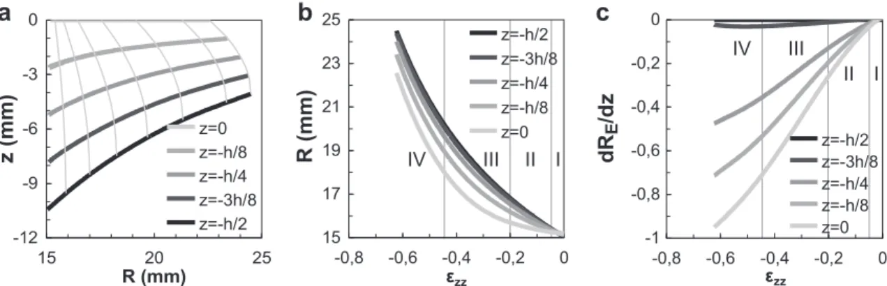
The sample profile is fitted using a quadratic polynomial in or-der to facilitate the evaluation of geometrical parameters (height, REmax, dRE/dz. . .) as seen inFig. 6. Stress (Eq.(17)) is plotted as a
function of strain from squeezing load measurement (Fig. 5). The
collected data allow to divide the squeezing sequence into four steps (Figs. 5 and 7). The first step (small strains) involving linear behavior due to instantaneous elastic response of the material, is followed by relaxation phenomena. The second step is defined by a slow stress increase until 20% strain due to viscous flow.
The trajectories of five points of the initial profile are plotted on
Fig. 8as well as radius REand profile slope dRE/dzas a function of
strain. During the second step, sliding with friction occurs as shown by linear radius increase (Fig. 8b) combined with nonlinear profile slope increase (Fig. 8c). Sliding was also investigated by post mortem sample observations, and it was found that no slip occurs above 800"C. In fact the sliding distance depends strongly on temperature (Fig. 7). Above 800"C, sliding amplitude is reduced (radius increase lower than 7%) and it can be neglected as it is currently the case in glass forming modeling[14](sticking conditions).
During the third step, radius increases exponentially, as well as stress, whereas the slope increases almost linearly as a result of sticking (Fig. 8). The fourth step takes place above 45% strain: the
Fig. 7. Contact conditions evolution during the tests (photograph of sample 7).
a
b
c
Fig. 8. Experimental data processing results: trajectories and profiles (at 1, 2, 3, 4, 5, 6, 6.5 s), radius R and profile slope dR/dz evolution with strain (sample 9, 800"C, 2 mm!s"1) of five profile points.
initial free lateral face close to the compression plates begins to stick on them. The data processing procedure, assuming slices method hypothesis, is no more valid in the two last steps. 4.2. Experimental verification of hypothesis
The sample volume is evaluated at any time by integration of the measured sample profile. Relative volume variation (volume variation/initial volume) during the tests is plotted inFig. 9a. It could be observed that the quasi-linear decrease of the volume is quite small during the test (less than 5%), and validates the incom-pressibility assumption.
Eqs.(7)–(9)assume that the maximal radius is located at the symmetry plane. This is verified for most of the tests, as reported inFig. 9b where the trajectories of the maximum radius point is plotted and compared to the middle of the two plates (continuous line). Both curves follow each other consistently, except at low temperature. At the beginning of the tests, the sample is cylindrical and the maximal radius point is not well defined. Nevertheless, it does not generate significant error because the radius is constant all along the profile and then its gradient is negligible. It can also be observed that the maximum radius point z-coordinate de-creases when the temperature inde-creases due to the creep of the sample while preheating.
The strain rate Dzzalong the squeezing axis has been evaluated
from radius measurement using Eq.(8)and compared to the usual evaluation from height measurement (ratio between velocity and height)[4].Fig. 9c shows that, in the present case, significant dif-ferences are observed (over 17%): strain rate from height data is under evaluated at low strain level (where the actual radius in-crease is higher due to barrel effect) and over evaluated at high strain level. The proposed method allow a more accurate identifi-cation since local input data are used.
4.3. Elastic modulus determination
As described in Section4.1, the stress initially increases linearly with strain as a result of instantaneous elastic response of the material. In this small strain range, loading is assumed to be unidi-rectional. The elasticity modulus is identified using (Eq.(20)) at the same time as viscosity (Fig. 5). Fig. 10shows its evolution with temperature above glass transition (600"C). A rapid decrease is ob-served until the modulus tends toward zero at elevated tempera-ture. If the curve trend matches bibliographical data, the values are significantly lower than those reported from ultrasonic mea-surement[5](about 30 GPa at 700"C). Nevertheless the results re-ported here are identified in situation close to processing condition and provide relevant test simulation results (cf. Section5).
4.4. Viscosity determination
From Eq.(20), squeezing stress is expressed for a CREEP law as a function of viscosity and measured parameters. It is then possible to identify the viscosity value that minimizes the bias between model and experiment. Nevertheless glass behavior is not strictly viscous and elastic deformation occurs as observed in Section4.1. Moreover the assumptions about bi-axial flow are not valid any more for high strains. It is therefore important to define an identi-fication strain range where elasticity could be neglected and flow assumptions are still valid. This is achieved in stage II between 10% and 20% strain, where experimental curves are very properly fitted (Fig. 5) by the model. The viscosity values identified for each test are plotted as a function of temperature (Fig. 11) and fitted by a Vogel–Tamman–Fulcher law[11], Eq.(21)where
g
is the viscos-ity, T the temperature, AVTF, BVTFand TVTFare material constants.log
g
¼ AVTFþT " TBVTFVTF ð21Þ
Fig. 11a reports the values of the viscosities evaluated in the present work using image processing and those given in the liter-ature (Sipp et al.[2]and Simmons et al.[9]for a close composition glass, and Arc International Cookware internal data for the same composition). In the identification range (650–900"C), viscosity
. . . .
Fig. 9. Relative evolution of sample volume while squeezing (a), trajectory of the maximum radius point while squeezing (b) and comparison of strain rate evaluated from height and radius data (sample 9).
values reported here (our experimental data) show a good agree-ment with the bibliographical data, and fill the gap between pre-existing experimental results. Moreover these values are in conti-nuity with Arc International Cookware data at higher and lower temperatures as shown by the Vogel–Tamman–Fulcher model (Fig. 11b).
4.5. Friction coefficient evaluation
As reported in Section4.1, during the second step of the tests, sliding occurs and viscous flow is predominant. The stress tensor components can be evaluated in this strain range, and especially tangential and normal stresses at sample/compression plate inter-face from Eqs.(18) and (19).Fig. 12shows the results for
r
zrandfor
r
zz, i.e. the shear and normal contact stresses. After an initiallinear increase of both components, the tangential stress increases more slowly until a maximal value. In the linear range, the ratio be-tween tangential and normal stresses was evaluated to be close to 0.8 under glass pressing conditions. This value can be compared to those reported in the literature for glass gob sliding conditions in the delivery system and ranging from 0.4 to 0.8[33]; these values are depending on glass temperature and materials in contact under conditions where metallic substrate and glass are not at the same temperature and contact time is very short.
5. FEM modeling of sample squeezing
The FEM modeling of the tests aims at providing a validation of the material parameters identification process by comparing experimental results to simulation.
5.1. Abaqus creep model
The modeling of viscous materials can be carried out with the CREEP law available in Abaqus commercial software[34], associ-ated to a generalized Hooke’s elasticity law. This power law, Eq.
(22), relates the uniaxial equivalent creep strain rate _!
e
cr, theuniax-ial equivalent deviatoric stress ~q (here Mises equivalent stress) and time t when ‘‘time hardening’’ option is selected.
a
b
Fig. 11. Viscosity results: (a) measurement using contactless instrumentation compared to literature (Sipp et al.[2], Simmons et al.[9]and Arc International Cookware internal data, referred to as AIC) and (b) Vogel–Tamman–Fulcher fitting of different sets of viscosity data.
Fig. 12. Tangential stress as a function of normal stress at sample/plate interface in the viscous flow range, step II (sample 9).
_!
e
cr¼ A~qntm _!e
cr¼ ffiffiffiffiffiffiffiffiffiffiffiffiffiffiffiffiffiffi2 3e
_ cr : _e
cr q ~ q ¼ ffiffiffiffiffiffiffiffiffiffiffiffi3 2S : S q ð22ÞIn Eq.(22), _
e
cris the creep strain rate tensor and S is thedevia-toric stress tensor. A, n and m are model parameters. Total strain tensor
e
is defined as a sum of an elastice
eland a creepe
crstraintensors, Eq.(23).
e
¼e
elþe
cr ð23ÞTo model Newtonian viscous flow, n is set to 1 and m to 0 and the parameter A is linked to the viscosity
g
according to Eq.(24), (deduced from the Mises stress calculation for a Newtonian fluid).A ¼31
g
ð24Þ5.2. Input data and calculation processing
A quarter of the section of the axisymmetric sample is modeled by a 15 # 10.4 mm2 rectangle (exact dimensions of sample n"9)
and meshed with 988 quadrangular linear elements as depicted inFig. 13. A symmetry axis is imposed on a vertical edge, number 1, and a symmetry plane on an horizontal edge, number 2, of the mesh. The second vertical edge, number 3, is free whereas the sec-ond horizontal edge, number 4, is in contact with a rigid plane sim-ulating the compression plate. Sticking conditions between sample and plate are defined on edge 4 as it could be assumed above Table 3
Computation input data.
Viscosity CREEP law Elasticity
g(Pa!s) A(Pa"1!s"1) m n E(MPa) m
106.92 4.15 10"8 1 0 280 0.499
800"C from experimental observations (Section 4). A constant crosshead displacement rate is modeled by setting half the com-pression velocity on the rigid plane.
Input data required for the computation are listed inTable 3. Poisson’s ratio,
m
, is set to 0.499 to approximate an incompressible flow without numerical instability. Calculation duration is less than one minute (2.6 GHz processor, 3 Go RAM) and is performed without remeshing until the end of the test.5.3. Results and comparison to experiment
The computation results are compared to experimental data in order to validate the parameter identification methodology pro-posed in Sections2 and 3. The data available for this comparison are the load evolution while squeezing and the deformed sample profile.Fig. 14shows that the profile of the sample is very properly predicted despite the strong contact assumption. A very good agreement between computed and experimental squeezing load (relative error lower than 5% until 30% strain) is observed even for strains over the viscosity identification range. The experimental steps I and II described in Section4.1are perfectly reproduced, as well as the beginning of the third step. For very high strains how-ever (end of the third step and fourth step) the computed load is overestimated (arising 160% at the end of the test) probably due to sliding at the contact points during experiment, but also shear thinning effect under high stresses. Moreover numerical errors may occur in this strain range because of elements distortion. 6. Conclusion
An analytical method is proposed to process elasticity and vis-cosity data of glassy materials from contactless instrumented high temperature squeeze tests. Specific measurement methods such as video measurement of specimen shape are required to check the validity of the assumptions and feed in the identification method-ology with data. Values of elasticity modulus and viscosity are pro-vided even above glass transition by taking into account barrel effect. Pyrex!borosilicate viscosity values were compared to
bib-liographical data and where found to fill properly the gap between the values reported for lower temperature (compression tests) and higher temperatures (shear tests). Contactless instrumentation also provides sample/plate contact data useful to understand the test phenomenology. Moreover the feasibility of friction factor evaluation during squeezing was verified using this method. Numerical simulation has shown that elastic and viscous parame-ters, despite a simplified identification, provide relevant data for the modeling of the glass viscous and elastic behavior using a creep model.
Acknowledgments
The present work has been carried out with the financial sup-port of Arc International Cookware, Aubert & Duval and Saint-Gob-ain SEVA. Special thanks are expressed to M. Daniel Deletang and his team who supplied the material for the machining of the samples.
References
[1] G. Dusserre, F. Schmidt, G. Dour, G. Bernhart, Thermo-mechanical stresses in cast steel dies during glass pressing process, J. Mater. Process. Tech. 162–163 (2005) 484–491.
[2] A. Sipp, D.R. Neuville, P. Richet, Viscosity, configurational entropy and relaxation kinetics of borosilicate melts, J. Non-Cryst. Solids 211 (1997) 281– 293.
[3] G. Dusserre, G. Dour, G. Bernhart, In-situ determination of the heat flux density at the glass/mould interface during a glass pressing production cycle, Int. J. Therm. Sci. 48 (2009) 428–439.
[4] D.R. Neuville, P. Richet, Viscosity and mixing in molten (Ca, Mg) pyroxenes and garnets, Geochim. Cosmochim. Ac. 55 (1991) 1011–1019.
[5] H. Hessenkemper, R. Brückner, Elastic constants of glass melts above the glass transition temperature from ultrasonic and axial compression measurements, Glastechn. Ber. 64 (1991) 29–38.
[6] J.H. Simmons, R. Ochoa, K.D. Simmons, J.J. Mills, Non-newtonian viscous flow in soda-lime-silica glass at forming and annealing temperatures, J. Non-Cryst. Solids 105 (1988) 313–322.
[7] Glass-viscosity and viscometric fixed points. Part 2: determination of viscosity by rotation viscometers. ISO 7884-2, first ed., 1987-12-15.
[8] J.H. Simmons, S.A. Mills, A. Napolitano, Interaction of microstructure development with viscous flow processes in glass, J. Non-Cryst. Solids 14 (1974) 302–309.
[9] J.H. Simmons, S.A. Mills, A. Napolitano, Viscous flow in glass during phase separation, J. Am. Ceram. Soc. 57 (1974) 109–116.
[10] Glass-viscosity and viscometric fixed points. Part 3: determination of viscosity by fibre elongation viscometers. ISO 7884-3, first ed., 1987-12-14.
[11] G.S. Fulcher, Analysis of recent measurements of the viscosity of glasses, J. Am. Ceram. Soc. 8 (1925) 339–355.
[12] D. Lochegnies, C. Marechal, Inverse determination of glass viscosity and heat transfer coefficient by industrial testing, Glass Sci. Technol. 75 (2002) 304– 312.
[13] D. Lochegnies, C. Marion, E. Carpentier, J. Oudin, Finite element contribution to glass manufacturing control and optimisation. Part 1. creep forming of flat volumes, Glass Technol.-Eur. J. Glass Sci. Technol. Part A 37 (1996) 128–132. [14] D. Lochegnies, C. Marion, E. Carpentier, J. Oudin, Finite element contribution to glass manufacturing control and optimisation. Part 2. blowing, pressing and centrifuging of hollow items, Glass Technol.-Eur. J. Glass Sci. Technol. Part A 37 (1996) 169–174.
[15] G. Adam, J.H. Gibbs, On the temperature dependence of cooperative relaxation properties in glass-forming liquids, J. Chem. Phys. 43 (1965) 139–146. [16] Y. Bottinga, P. Richet, Silicate melt structural relaxation : rheology, kinetics and
Adam-Gibbs theory, Chem. Geol. 128 (1996) 129–141.
[17] M. Ali Bouhifd, A. Sipp, P. Richet, Heat capacity, viscosity, and configurational entropy of alkali titanosilicate melts, Geochim. Cosmochim. Ac. 63 (1999) 2429–2437.
[18] J. Engmann, C. Servais, A.S. Burbidge, Squeeze flow theory and applications to rheometry: a review, J. Non-Newton. Fluid Mech. 132 (2005) 1–27. [19] G. Karapetsas, J. Tsamopoulos, Transient squeeze flow of viscoplastic materials,
J. Non-Newton. Fluid Mech. 133 (2006) 35–56.
[20] N. Delhaye, A. Poitou, M. Chaouche, Squeeze flow of highly concentrated suspensions of spheres, J. Non-Newton. Fluid Mech. 94 (2000) 67–74. [21] C.J.S. Petrie, The rheology of fibre suspensions, J. Non-Newton. Fluid Mech. 87
(1999) 369–402.
[22] A. Matsoukas, E. Mitsoulis, Geometry effects in squeeze flow of Bingham plastics, J. Non-Newton. Fluid Mech. 109 (2003) 231–240.
[23] P. Richet, M. Ali Bouhifd, P. Courtial, C. Téqui, Configurational heat capacity and entropy of borosilicate melts, J. Non-Cryst. Solids 211 (1997) 271–280. [24] K. Ota, W.J. Botta, G. Vaughan, A.R. Yavari, Glass transition Tg, thermal
expansion, and quenched-in free volume dvf in pyrex glass measured by time-resolved X-ray diffraction, J. Alloy Compd. 388 (2005) L1–L3.
[25] J.H. Simmons, Refractive index and density changes in a phase-separated borosilicate glass, J. Non-Cryst. Solids 24 (1977) 77–88.
[26] P. Manns, W. Döll, G. Kleer, Glass in contact with mould materials for container production, Glass Sci. Technol. 68 (1995) 389–399.
[27] M. Bornert, F. Brémand, P. Doumalin, J.C. Dupré, M. Fazzini, M. Grédiac, F. Hild, S. Mistou, J. Molimard, J.J. Orteu, L. Robert, Y. Surrel, P. Vacher, B. Wattrisse, Assessment of digital image correlation measurement errors: methodology and results, Exp. Mech. 49 (2009) 353–370.
[28] H.M. Laun, M. Rady, O. Hassager, Analytical solutions for squeeze flow with partial wall slip, J. Non-Newton. Fluid Mech. 81 (1999) 1–15.
[29] G.H. Meeten, Effects of plate roughness in squeeze-flow rheometry, J. Non-Newton Fluid Mech. 124 (2004) 51–60.
[30] J.D. Sherwood, Liquid–solid relative motion during slow squeeze flow of pastes, J. Non-Newton. Fluid Mech. 128 (2005) 163–171.
[31] F. Kolenda, P. Retana, G. Racineux, A. Poitou, Identification of rheological parameters by the squeezing test, Powder Technol. 130 (2003) 56–62. [32] G. Dusserre, G. Uksksk, Thermomechanical loading in a cast martensitic
stainless steel mould during a glass pressing cycle (in french), Ph. D. thesis, Université de Toulouse, USA, 2006.
[33] M. Falipou, F. Sicloroff, C. Donnet, New method for measuring the friction between hot viscous lass and metals, Glass Sci. Technol. 72 (1999) 59–66. [34] H.D. Hibbitt, B. Karlsson, E.P. Sorensen, ABAQUS User’s Manual, Providence, RI,
![Fig. 1. Temperature range of the different set of bibliographical data [2,9].](https://thumb-eu.123doks.com/thumbv2/123doknet/12272321.321743/3.892.60.415.140.290/fig-temperature-range-different-set-bibliographical-data.webp)