HAL Id: hal-02044399
https://hal.archives-ouvertes.fr/hal-02044399
Submitted on 9 Jun 2019
HAL is a multi-disciplinary open access archive for the deposit and dissemination of sci-entific research documents, whether they are pub-lished or not. The documents may come from teaching and research institutions in France or abroad, or from public or private research centers.
L’archive ouverte pluridisciplinaire HAL, est destinée au dépôt et à la diffusion de documents scientifiques de niveau recherche, publiés ou non, émanant des établissements d’enseignement et de recherche français ou étrangers, des laboratoires publics ou privés.
Numerical study of the screw-nut movement in the
self-loosening process under transverses loading
Vincent Rafik, Alain Daidié, Bertrand Combes
To cite this version:
Vincent Rafik, Alain Daidié, Bertrand Combes. Numerical study of the screw-nut movement in the self-loosening process under transverses loading. 15e colloque national AIP-PRIMECA, 2017, Plagne-Montalbert, France. �hal-02044399�
15e Colloque National AIP-Priméca 1/6 La Plagne (73) – 12 au 14 avril 2017
Numerical study of the screw-nut mouvement in the
self-loosening process under transverses loading.
Vincent Rafik
Université de Toulouse, Institut Clément Ader, UMR CNRS 5312,
INSA/UPS/ISAE/Mines Albi 3 rue Caroline Aigle 31400 Toulouse – France vincent.rafik@insa-toulouse.fr
Alain Daidié
Université de Toulouse, Institut Clément Ader, UMR CNRS 5312,
INSA/UPS/ISAE/Mines Albi 3 rue Caroline Aigle 31400 Toulouse – France alain.daidié@insa-toulouse.fr
Bertrand Combes
Université de Toulouse, Institut Clément Ader, UMR CNRS 5312,
INSA/UPS/ISAE/Mines Albi 3 rue Caroline Aigle 31400 Toulouse – France bertrand.combes@insa-toulouse.fr
Abstract — Self-loosening of bolted assemblies under transverse loading is an issue studied several times. A first study axe is the role of sliding, localized or generalized, in threads. A second study axe is the kinematic and the relative movement between the nut and the screw. The aim of this paper would be to study those aspects by observing the behavior of a double shear assembly. Thus a numeric model, factoring the threads, the boundaries conditions and the contacts in, has been developed. In the first instance, the macroscopic and microscopic behaviors, respectively self-loosening and localized slip, were observed. In the second instance, a study of the relative movement between the screw and the nut highlighted a tilting one from another, in accordance with the hypothesis made by Kasei. Therefore, this paper contributes to support the self-loosening process evolved by Kasei.
Key Word — self-loosening, relative movement, sliding, numerical model, bolted assemblies.
I. INTRODUCTION :
A. Industrial and scientific context :
When a structure is solicited, its bolted assemblies also perceive loading or displacement. Those excitations are a source of phenomena which sometimes imply bonding’s damage. Several failures can be observed during functioning, leading to a loss of preload of the screw. If this downgrading is too important, the assembly cannot be considered as an embedding and the structural integrity cannot be assured. This phenomenon is recurring in the automobile or aeronautic industries. We are used to increase to preload in order to raise the life length of the joint, despite an increase of the dimensions and thus of the mass. Yet, it has been shown that a loss of preload is often linked to the unscrewing [1]. A better understanding of self-loosening will enable to reduce the global price and the mass of many structures, as well as, increasing their life length.
The interest of a phenomenological study of assemblies self-loosening is the understanding of the process leading to the loss of preload. In the literature, some authors studied this phenomenon ([1], [2], [3], [4], [5], [6] and [7]). Two concepts need to be distinguished: unscrewing and untightening. Untightening is a static phenomenon: no kinematic takes place.
Mating, creeping or differential dilatation can be its reasons. For unscrewing, the rotation of the nut or the screw implies a loss of preload due to the helicoid shape of the threads.
Dinger [1] distinguished four cases of loading leading to self-loosening as shown in the Figure 1.
Transverse loading: the excitation force is orthogonal to the screw axis (case A).
Central axial loading: The force direction matches the screw axis (case B).
Hexcentric axial loading: the force direction is collinear to the screw axis but does not match it (case C)
Rotational loading: the screw is submitted to a torque along it axis (case D).
Figure 1 : Différents cas de chargement, d’après [1] : A : transversal ; B : axial ; C : excentré ; D : rotationnel.
The most outstanding work will be analyzed next. B. Self-loosening in the literature :
Junker [2] seems to be the first to interest himself for self-loosening under transverse loading. His observations are based on results he got thanks to a specific test bench (Figure 2). Two plates are tightened together thanks to a preloaded bolt. An electric motor whose rotor is bonded to an adjustable hexcentric generates a transverse movement of the upper plate while the lower one is fixed. In a subsequent phase, once the role of sliding have been identified and wishing to consider the most critical case, Junker modified his mounting in order to minimize the friction. Then he put needles bearing between the two plates. This assembly is used to assess the effectiveness of
15e Colloque National AIP-Priméca 2/6 La Plagne (73) – 12 au 14 avril 2017
a locking solution as most friction are minimize. However, this device is not consistent with most of industrial assembly. We will be studying the most widespread arrangement: double lap assemblies.
Figure 2 : Banc d'essais de Junker, [2]
The emergence and the development of numerical tools enabled a new interpretation of the problematic. Indeed, thanks to finite element methods, new theories and concepts were developed. The latter are based on local measure which was not possible and still are not possible during experiments. Thus, Hess ([3], [4], [5] and [6]) defined a new notion: the localized slip, opposed to generalize slip. If localized slip occurs, only a part of the contact’s surface slips while the rest of the surface sticks. The built model (Figure 3) highlighted the existence and the role of this slipping during the unscrewing of a bolted assembly. It can be splatted into three parts: the top plate, the screw and the threaded insert. Each of these solids is meshed independently. A vertical displacement applied to the top plates induces the preload of the assembly. The loading is applied through a spring. Its stiffness is determined in order to be equivalent to the component’s one assuring the load transfer. The lateral sides are constraints to remain flat, external surfaces of the insert are embedded. Three contacts have been defined between the different solids:
Between the screw head and the external surface of the plate,
Between the grip and the plate’s drilling,
Between the screw’s thread and the threaded insert.
Figure 3 : Model developed by Hess, [3]
It can be seen that the model developed by Hess is quite basic as it does not represent a whole assembly. However, it enables him to show that generalized slip is not complementary for self-loosening as localized slip is sufficient. Moreover, the preload might be misapplied as it does not factor the plastic strain of the thread or the screw’s twisting when the assembly is tightened. A model compensating those limitations will be built.
Kasei ([7] and [8]) gave another explanation to self-loosening under transverse loading. He does not question the role of the sliding in self-loosening but he believes that another phenomenon contribute to it. He considers that when the screw is bending due to the transverse loading, a relative movement between the screw and the nut exists. Indeed, functional clearances allow a degree of freedom in rotation (angle i in Figure 4) in the threaded connection. Assuming that the instantaneous center of rotation is located at the intersection of the bolt’s revolution axis and of its median plane, he showed that the angular displacement implies a transverse displacement. The latter generates the torsion of the screw or of the nut as transverse and circumferential translations are linked together. If the reaction efforts induced by the twisting are greater than the frictional forces, then, an increment of self-loosening happens.
15e Colloque National AIP-Priméca 3/6 La Plagne (73) – 12 au 14 avril 2017
Figure 4 : Kasei analytical model, [5].
Ksentini ([9]) interested herself in the study of self-loosening under transverse dynamic loading. She considered a single lap assembly (Figure 5), transversally solicited thanks to a shaker and an inertial mass.
Figure 5 : Ksentini’s model [9]. C. Objectives of our study :
The aim of the following work is to build a numeric model using the Abaqus software which would meet the shortage of the presented models. Thanks to our model, we could reproduce the observation made by Hess ([3], [4] and [5]) and by Kasei ([7] and [8]). It will act as support in order to put forward an explanation to self-loosening, taking inspiration from Kasei theory. We will particularly interest ourselves in the microscopic and macroscopic behaviors in order to approve the remarks made by Hess or Kasei.
We will study a screw dedicated to the aeronautical domain, which has the particularity to be held not-rotatably, during the tightening, thanks to a hexagonal socket located near the threads. Thus, we could study self-loosening undependably from the initial twist of the screw. In order to reduce the bending forces applied to the screw when a single lap assembly is considered, a double lap one will be studied. Another modification from the Ksentini’s model would be the kind of excitation. Indeed, the problem will be solved considering quasi-static forces in order to match industrial problems.
II. THENUMERICALMODEL:
The adapted geometry (Figure 6) for the development of the numerical model represents a double lap assembly, composed of 3 plates, a titanium aeronautical screw and nut.
Figure 6 : Numerical model’s geometry.
To have a finer mesh for the screw and nut threads, independent solids will be created. The latters will be anchored to the rest of the screw or the nut. In order to limit the error implied by this bonding, we have moved it away from the threads by creating a socket around the threads. Figure 7 shows the socket and the body of the screw.
Figure 7 : The two parts composing the screw.
The used material for the plates is the aluminum 2024 while the screw and the nut are the titanium TA6V. The plasticity of the material has been modeled thanks to a kinematic strain-hardening. They were defined by mean of the Young modulus, Poisson coefficient and 2 stress-plastic strain couples. The values are listed in the Table 1
Materials E ν (σ1,εp1) (σ2,εp2)
Aluminium 73000 MPa 0,3 (345 MPa, 0) (541 MPa, 0,177) Titanium 113800 MPa 0,3 (880, MPa, 0) (950 MPa, 0,14)
Tableau 1 : materials definitions
In order to get closer to a real assembly, several contacts have to be defined. (Figure 6):
Between the nut and the plate (contact n°1), Between the threads of the screw and of the nut
(contact n°2),
Between the body of the screw and the plates boring (contact n°3),
Between the plates (contact n°4),
Between the screw head and the plates (contact n°5).
The normal behavior of the contact has been solved thanks to the Lagrange methods while the tangential behavior has been solved using the penalty method in order to ensure the convergence of the calculations and considering a friction coefficient. Their values are stated in the Table 2.
15e Colloque National AIP-Priméca 4/6 La Plagne (73) – 12 au 14 avril 2017
Contact Coefficient de frottement Comportement normal
1 0,09 Lagrange 2 0,07 3 4 0,16 5 0.09
Tableau 2 : Définition des contacts.
Three calculation steps have been created in the model. The first one, Figure 7, is the tightening of the nut on the screw in order to apply the preload. The hexagonal socket of the screw has been embedded while a rotation has been applied to the nut.
Figure 8 : Etape de serrage de l'assemblage
The second step is the relaxation throughout only the screw is held not-rotatably and enables the stress to homogenize. Finally, in the last one (Figure 9), the edges of the external plates are embedded while the edge of the central plate is solicited either in displacement (1) or in effort. The loading’s profile had been chosen according to Dinger’s works [1] in order to choose the most critical configuration:
Displacement (mm) : D(t) = 0,25 + 0,75.sin(1,57.t) (1) effort (N) : F(t) = 17500 + 22500.sin(1,57.t) (2)
Figure 9 : Etape de sollicitation cyclique.
III. PRESENTATION AND RESULTS’S ANALYSIS :
The results from this model, driven in displacement, have been confronted to the existing one ([1], [2], [3], [4] and [5]). The temporal evolution of the screw normal strength have been noted (Figure 10) by integrating the normal stress over a section. The curve obtained shows 3 different stages:
Stage 1: tightening and relaxation. The value of normal effort raises, prorated to the nut’s rotation up to the value of preload. This behavior is consistent with the theory as normal strength is linked to the screw elongation thus to the tightening angle.
Stage 2: loosening transient state. During this stage, there is a nonlinear reduction of the preload. An interpretation to this behavior can be given: In the first cycles, there could be plastic strain of the different solids, especially in the nut and screw’s threads. Thus, while the plastic strain accrues, the behavior can’t be linear as the thread’s geometry is affected. Some cyclical variation can be observed. Stage 3: quasi steady state. Self-loosening keeps
on occurring. The same cyclical variation can be
noticed. An interpretation of this behavior will be put forward by studying the variation over one cycle of the normal effort (Figure 11).
Figure 10 : Evolution de l'effort normal sur 15 cycles.
Figure 11 : Evolution de l'effort normal sur un cycle.
This curve can be splatted into 4 portions per half cycle. In a first step, a slope (AB) can be noticed which correspond to the sticking of the different surfaces. The screw is bending, then the elongations of the neutral fiber imply a raise of the preload. In a second step, a plateau (BC) can be observed. It matches with the sliding of the nut or the screw on the plates. If one surface or the other is sliding, then the screw does not bend anymore and the normal effort does not raise anymore. In a third step, there is sudden change (CD) of the normal strength, which could correspond to the sliding of the screw on the nut and to the loosening of the assembly. In a fourth step, there is a slope (DE) as the screw goes back to its initial position.
The numerical model also highlighted the behavior of the contact in the threading (Figure 13) during the cycling. It can be noticed that some areas are sliding (in green) whereas others are sticking (in red). It seems that localized could explain self-loosening, in accordance to Hess theory.
‐1000 0 1000 2000 3000 4000 5000 0 10 20 30 40 50 60 Effor t nor mal ( N ) Temps (s) 3 2 1 14000 14200 14400 14600 14800 15000 15200 15400 15600 77 78 79 80 81 82 83 Effor t nor mal ( N ) Temps (s) D(t) or F(t) Rotation imposée Encastrement A B C D E
15e Colloque National AIP-Priméca 5/6 La Plagne (73) – 12 au 14 avril 2017
Figure 12 : Etat des surfaces de contact pour plusieurs stades de chargement.
The model can be driven either in displacement or in effort, it is complementary to check if the two models are equivalent. To do so, firstly, a effort driven calculous have been launch. The displacement of the edge of the central plate and the normal strength have been recorded. Secondly, the model is displacement driven, the excitation stemming from the previous results. The evolution of the normal force and of the displacement have been compared. The obtained curves overlaps very well (Figure 13), then, it can be conclude that the two setpoints are equivalent.
Figure 13 : Evolution de l'effort normal. Commandé en effort (rouge) et en déplacement (bleu)
The observations made above enable to retrieve contents existing in the theory of Hess [2] or Kasei [5] : localized slipping and self-loosening. However, in order to support the works developed by the Japanese, it is complementary to study the relative movement between the screw and the nut, which can be seen as rigid body.
IV. HIGHTLIGHTING OF RELATIVE MOUVEMENT:
Kasei considered that the relative movement between the screw and the nut was a rotation, which, once projected in the median plane of the assembly, was presenting a Instantaneous Rotation Center (IRC) located at the intersection of the screw axis and the median plane of the nut. We propose to numerically analyze this relative movement in order in review the hypotheses.
By taking the case of loading at the point B, C and D (Figure 13), it can be noticed that the angular position of the screw (whose axis is in red) isn’t the nut’s one (whose axis is in black) on the Figure 14. The angular displacement is about 2°.
Figure 14 : Positions relatives de la vis et de l'écrou au cours du cycle de chargement
Thanks to this observation, a relative movement between the nut and the screw exists.
If the path of 4 points spread along the perimeter of the screw’s bottom is recorded (Figure 15), it is possible to gather further information about the movement.
Figure 15 : Définition des 4 points pour l'étude de la trajectoire.
In order to correctly analyze the point’s paths, we have to carry out a basis change (Figure 16) in order not to factor self-loosening.
Figure 16 : Définition des repères fixe et mobile.
For each point, we calculate its displacement it the median plane by deducting from the real displacement the effect of the helicoidally movement implied by the unscrewing.
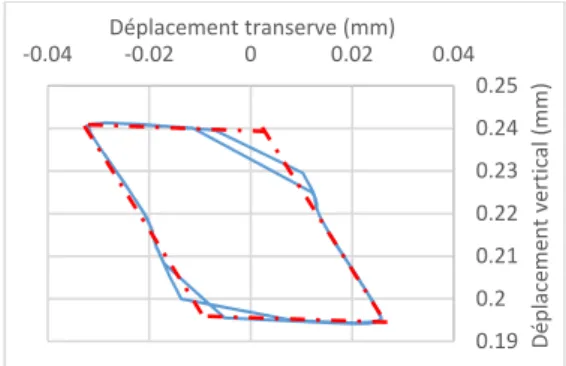
The displacement of the point 2 and 4 are identical: thus, the rotating movement is included in the plane orthogonal to the line defined by the point 2 and 4. The path of the points 1 and 3 (Figure 17) are similar and do not have any tangential components. Then, the rotation seems to be included in the median plane of the assembly.
The path can be divided into 4 segments, parallel side by side, (in red dotted line on Figure 17). Horizontal segments represent the transverse sliding of the bolt, while the transverse loading is not high enough to overcome the friction forces. The 20000 21000 22000 23000 24000 25000 26000 27000 28000 3 3.5 4 4.5 Effor t nor mal ( N ) Temps (s) Point 4 Point 3 Point 2 Point 1 Direction de la sollicitation
Point A Point B Point C Point D direction
de la sollicitation
Point B Point C
15e Colloque National AIP-Priméca 6/6 La Plagne (73) – 12 au 14 avril 2017
leaning segments represent the relative movement of the screw in the nut. The angle between those lines and the horizontal is about 60°, which is the value of the threads top angle. We can assume that this movement could be that of a solid laying on the nut’s threads and moving along them in the median plane.
Figure 17 : Trajectoire du point 1 sur 2 cycles de chargement
V. CONCLUSION :
Self-loosening of a bolted assembly has been studied by Junker in the late 60’s. The sliding of surfaces is one explanation which has been given. Hess believes that self-loosening can occurs even if the whole surface isn’t sliding, he call this phenomena localized sliding.
Kasei considers the relative movement between the nut and the screw when the latter is bending. This movement could contribute to loosen the bolt: Kasei shows that any transverse displacement implies the twist of the screw. According to him, this twist could lead to the screw rotation and thus to the self-loosening.
We developed a numerical model taking into account threads, contacts and the tightening of a double lap assembly solicited transversally. It allowed us to highlight loosening under localized slip and to show the relative movement of the screw against the nut. The study of the path of four different points of the screw has shown that this movement was a tilting of the screw in the nut and was included in the median plane of the assembly. By analyzing those paths, we have defined an area of existence of the Instantaneous Rotation Center.
It should be interesting to determine the exact position of this point, throughout the loading cycle. A modeling and an analytical solving of the self-loosening could be feasible, in order to get an life length definition under transverses loading.
VII) Bibliography :
[1] G. Dinger. " Ermittlung des selbsttätigen Losdrehens bei mehrschraubenverbindungen ", 2013, ISBN 978-3-8440-2426-5
[2] G.H. Junker, "New criteria for self-loosening of fasteners under vibration", SAE Technical Paper 690055, 1969, DOI : 10.427/600055
[3] J.A. Sanclemente, D.P. Hess, "Parametric study of threaded fastener loosening due to cyclic transverse loads", Engineering Failure analysis 14 (2007), p239- 249, DOI : 10.1016/j.engfailanal.2005.10.016, 2006. [4] N.G. Pai, D.P.Hess, "Three-dimensional finite element
analysis of threaded fastener loosening due to dynamic
shear load", Engineering Failure analysis 9 (2002), p383-402, 200
[5] R.I. Zadoks, "An investigation of the self-loosening behavior of bolts under transverse vibration", Journal of sound and vibration (1997), 208(2), p189-209, 1997. [6] N.G. Pai, D.P. Hess, "Experimental study of loosening of
threaded fastener due to dynamic shear loads", Journal of Sound and Vibration (2002), 253(3), p585-602, DOI : 10.1006/jsvi.2001.4006, 2001,
[7] Akira YAMAMOTO, Shinji KASEI, “Investigations on the self-loosening of threaded Fasteners under Transverse Vibration ---A solution for self-loosening Mechanism---“ [8] S. Kasei, "A study of self-loosening of bolted joints due
to repetition of small amount of slippage at bearing surface", Journal of advanced mechanical design, systems and manufacturing, Vol. 1, No. 3, DOI : 10.1299/jamdsm.1.358, 2007.
[9] O. Ksentini, "Etude du devissage spontané d’un assemblage boulonné soumis à des sollicitations transverses dynamiques", Thèse, Institut Clément Ader, Toulouse, 2016, 0.19 0.2 0.21 0.22 0.23 0.24 0.25 ‐0.04 ‐0.02 0 0.02 0.04 Déplacement vertical (mm) Déplacement transerve (mm)
![Figure 1 : Différents cas de chargement, d’après [1] : A : transversal ; B : axial ; C : excentré ; D : rotationnel](https://thumb-eu.123doks.com/thumbv2/123doknet/12255158.320370/2.892.460.836.671.826/figure-différents-chargement-après-transversal-axial-excentré-rotationnel.webp)
![Figure 3 : Model developed by Hess, [3]](https://thumb-eu.123doks.com/thumbv2/123doknet/12255158.320370/3.892.89.425.178.528/figure-model-developed-hess.webp)