The X-ray Integral Field Unit (X-IFU) for Athena
Laurent Ravera
ab, Didier Barret
ab, Jan Willem den Herder
c, Luigi Piro
d, Rodolphe Cl´edassou
e,
Etienne Pointecouteau
ab, Philippe Peille
ab, Fran¸cois Pajot
abf, Monique Arnaud
g, Claude
Pigot
g, Lionel Duband
h, Christophe Cara
g, Roland H. den Hartog
c, Luciano Gottardi
c, Hiroki
Akamatsu
c, Jan van der Kuur
c, Henk J. van Weers
c, Jelle de Plaa
c, Claudio Macculi
d, Simone
Lotti
d, Guido Torrioli
i, Flavio Gatti
j, Luca Valenziano
k, Marco Barbera
l, Xavier Barcons
m,
Mar´ıa Teresa Ceballos
m, Lourdes F`abrega
n, Jos´e Miguel Mas-Hesse
o, Mathew J. Page
p, Phillip
R. Guttridge
p, Richard Willingale
q, St´ephane Paltani
r, Ludovic Genolet
r, Enrico Bozzo
r,
Gregor Rauw
s, Etienne Renotte
s, J¨orn Wilms
tand Christian Schmid
t aUniversit´e de Toulouse, UPS-OMP, IRAP, Toulouse, France;
b
CNRS, IRAP, 9 Av. colonel Roche, BP 44346, 31028 Toulouse cedex 4, France;
cSRON, Sorbonnelaan 2, 3584 CA Utrecht, The Netherlands;
d
INAF/IAPS Roma, Via Fosso del Cavaliere 100, 00133 Roma, Italy;
eCNES, 18 avenue Edouard Belin, 31 401 Toulouse cedex 9, France;
f
IAS, Centre universitaire d’Orsay, 91405 Orsay cedex, France;
gCEA/IRFU, 91191 Gif-sur-Yvette cedex, France;
h
CEA/INAC-SBT, 17 rue des Martyrs, 38054 Grenoble cedex 9, France;
iCNR/IFN Roma, Via Cineto Romano 42, 00156 Roma, Italy;
j
INFN-Physics Department Genova University Via Dodecaneso 33, 16146 Genova, Italy;
kINAF-IASF Bologna, via Piero Gobetti 101, 40129 Bologna, Italy;
l
University of Palermo, Via Archirafi 36 I, 90123 Palermo, Italy;
mIFCA (CSIC-UC), Avenida de Los Castros s/n, 39005 Santander, Spain;
nICMAB-CSIC, Campus Universitat Aut`onoma de Barcelona, Bellaterra 08193, Spain;
o
CAB (CSIC-INTA), POB 78, 28691 Villanueva de la Canada, Madrid, Spain;
pMSSL-UCL, Holmbury St. Mary, Dorking, Surrey, RH5 6NT, United Kingdom;
qUniversity of Leicester, University Road, Leicester, LE1 7RH, United Kingdom;
r
Universit´e de Gen`eve, Ch. d’Ecogia 16, 1290 Versoix, Switzerland;
sUniversit´e de Li`ege, All´ee du 6 aoˆ
ut, B-4000 Li`ege, Belgium;
t
Universit¨at Erlangen-N¨
urnberg, Sternwartstrasse 7, D-96049 Bamberg, Germany
ABSTRACT
Athena is designed to implement the Hot and Energetic Universe science theme selected by the European Space Agency for the second large mission of its Cosmic Vision program. The Athena science payload consists of a large aperture high angular resolution X-ray optics (2 m2at 1 keV) and twelve meters away, two interchangeable focal plane instruments: the X-ray Integral Field Unit (X-IFU) and the Wide Field Imager. The X-IFU is a cryogenic X-ray spectrometer, based on a large array of Transition Edge Sensors (TES), offering 2.5 eV spectral resolution, with∼500pixels, over a field of view of 50 in diameter. In this paper, we present the X-IFU detector and readout electronics principles, some elements of the current design for the focal plane assembly and the cooling chain. We describe the current performance estimates, in terms of spectral resolution, effective area, particle background rejection and count rate capability. Finally, we emphasize on the technology developments necessary to meet the demanding requirements of the X-IFU, both for the sensor, readout electronics and cooling chain.
Keywords: X-ray, missions, micro-calorimeter, Athena
1. THE ATHENA MISSION
Addressing the Hot and Energetic Universe science theme1requires an X-ray observatory-class mission delivering
a major leap forward in high-energy observational capabilities. Thanks to its revolutionary optics technology2
and the most advanced X-ray instrumentation, the Athena mission, will deliver superior wide field X-ray imaging, timing and imaging spectroscopy capabilities, far beyond those of any existing or approved future facilities. Like XMM-Newton today, Athena will play a central role in all fields of astrophysical investigations in the next decade. No other observatory-class X-ray facility is programmed for that timeframe, therefore Athena will provide our only view of the Hot and Energetic Universe, leaving a major legacy for the future.
The breadth of science achievable with the X-IFU touches most of the key issues identified in the Hot and Energetic Universe science theme. For the hot Universe, this ranges from understanding how baryons accrete and evolve in the largest dark matter potential wells of groups and clusters (see Athena supporting papers3, 4), how
and when the energy contained in the hot intra-cluster medium was generated and how jets from active galactic nuclei (AGN) dissipate their mechanical energy in the intracluster medium (see Athena supporting papers5).
X-IFU will also find the missing baryons at z<2 and reveal the underlying mechanisms driving the distribution of this gas on various scales, from galaxies to galaxy clusters, as well as metal circulation and feedback processes (see Athena supporting papers6). X-IFU observations will probe the first generation of stars to understand cosmic re-ionization, the formation of the first seed super-massive black holes, and the dissemination of the first metals (see Athena supporting papers7, 8). They will also reveal how accretion disks around black holes launch winds and outflows and how much energy they carry (see Athena supporting papers9). Similarly, AGN outflows and the processes by which the energy and metals are accelerated in galactic winds and deposited in the circum-galactic medium will be studied in details (see Athena supporting papers10). More generally, by
providing spatially resolved high-resolution X-ray spectroscopy, the X-IFU instrument will enable new science to be performed for a wide range of objects of great interest to the whole astronomical community, from planets, stars, supernova, binaries up to the most distant gamma-ray bursts (see Athena supporting papers11–15).
Figure 1. Simulated Athena observation of the Perseus cluster, highlighting the advanced capabilities for revealing the intricacies of the physical mechanisms at play. The left panel shows a simulated 50 ks X-IFU observation (0.5-7 keV), displayed on a log scale. The spectrum on the right is from the single 500×500
region marked by the box, with the existing Chandra ACIS spectrum for comparison. The inset shows the region around the iron L complex. With such observations velocity broadening is measured to 10-20 km/s, the temperature to 1.5% and the metallicity to 3% on scales <10 kpc in 20-30 nearby clusters, and on <50 kpc scales in hundreds of clusters and groups (taken from the Athena supporting papers5).
The illustration of the power of spatially resolved high-resolution X-ray spectroscopy is provided in Fig.1, taken from the Athena supporting papers,5 showing the simulation of a 50 ks X-IFU exposure of the Perseus cluster. Such measurements will enable us to pinpoint the locations of jet energy dissipation, determine the total energy stored in bulk motions, turbulence and weak shocks, and test models of AGN fuelling so as to determine how feedback regulates hot gas cooling.
2. THE X-IFU PERFORMANCE REQUIREMENTS AND BASELINE DESIGN
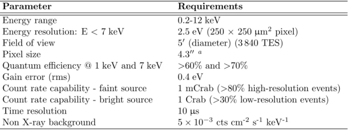
The X-IFU top-level performance requirements are listed in Tab. 1. The following sub-sections provide some of the most relevant information for the current X-IFU design, from the detection and readout principles to the mechanical, thermal and electrical architectures. The X-IFU mass, power and telemetry current best estimates are indicated in Tab. 2.
Table 1. Key performance requirements for the Athena X-IFU.
Parameter Requirements
Energy range 0.2-12 keV
Energy resolution: E < 7 keV 2.5 eV (250× 250 µm2pixel) Field of view 50 (diameter) (3 840 TES)
Pixel size 4.300 a
Quantum efficiency @ 1 keV and 7 keV >60% and >70% Gain error (rms) 0.4 eV
Count rate capability - faint source 1 mCrab (>80% high-resolution events) Count rate capability - bright source 1 Crab (>30% low-resolution events) Time resolution 10 µs
Non X-ray background 5× 10⁻³ cts cm-2 s-1 keV-1
aTo be compared with the mirror point spread function (PSF): 500
2.1 Detection and readout principle
The X-IFU detector is a large array of X-ray absorbers on top of Transition Edge Sensors (TES). The TES micro-calorimeter senses the heat pulses generated by X-ray photons when they are absorbed and thermalized. The temperature increases sharply with the incident photon energy and is measured by the change in the electrical resistance of the TES, which must be cooled to temperatures less than 100 mK (the thermal bath is at 50 mK) and biased in its transition between super conducting and normal states (see Fig. 2).
0 20 40 60 80 100 120 T (mK) 0 20 40 60 80 100 120 RTES (m Ω ) Superconducting Normal Transition RN TC Biasing ITES Bath (50,mK) V,,,,, Absorber TES Bias Weak, thermal, link Strong, thermal, link ,,,,Currentsensor −200 0 200 400 600 800 1000 Time (µs) Temperature
Figure 2. Principle of a Transition Edge Sensor (TES) acting as a micro-calorimeter. Left panel) The TES is cooled and voltage-biased to lie in its transition between its superconducting and normal states. Middle panel) The absorption of an X-ray photon heats both the absorber and the TES through the strong thermal link. Right) The change in temperature (or resistance) with time shows a fast rise (due to the strong link between the absorber and the TES) and a slower decay (due to the combination of a weak link with the 50 mK thermal bath and a negative electrothermal feedback).
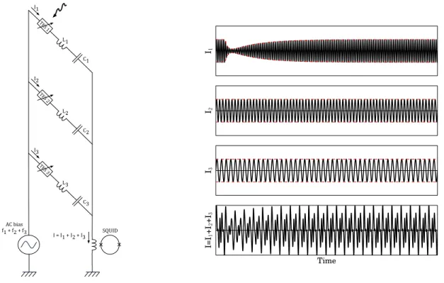
Two options are under consideration for the X-IFU sensors: Ti/Au bilayer TES with Cu/Bi absorbers16 or Mo/Au bilayer TES with Au/Bi absorbers.17 The absorber has a size of 250× 250 µm2. Either absorber can achieve the correct stopping power at 6 keV and provide low heat capacitance required for high spectral resolution. The small current of the TES is read out using a low noise amplifier chain consisting of a superconducting quantum interference device (SQUID) in the cold front end electronics (CFEE), SQUID array amplifiers at 2 K and a semi-conductor low-noise amplifier in the warm front end electronics (WFEE). Multiplexing allows the reduction of the number of readout channels and hence the thermal load on the cooling chain. For Frequency Domain Multiplexing (FDM), a single comb signal AC-biases each pixel with a specific carrier matching the resonant frequency of an LC circuit (see Fig. 4). De-modulation of the summed signal in the digital readout electronics (DRE) enables the reconstruction of the shape of the signal in each pixel. With a frequency range of ∼1 to 5 MHz and a carrier separation of 100 kHz, up to 40 pixels can be multiplexed in a single readout channel. To match the X-IFU field of view requirement (50 diameter), in its current design, 3 840 equal size pixels are required. These are read out in 96 channels of 40 pixels each.18 The first stage SQUID needs to be linearized with a high gain feedback loop. A so-called base-band feedback technique ensures that the feedback signal carrier is properly phased with the TES signal carrier at the SQUID input.19 Located closely underneath the TES array, an active anticoincidence layer (Cryo-AC) screens the high energy particle background.20–22 The Cryo-AC detection chain comprises 4 TES pixels and their related cryogenic SQUID and warm electronics.23
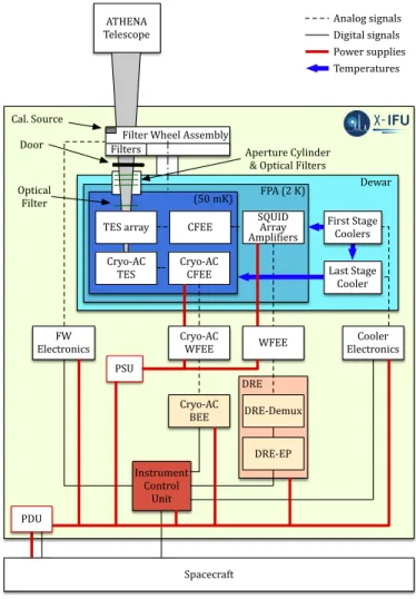
Fig. 3 shows the X-IFU block diagram.
(50$mK) SQUID$ Array$ Ampli4iers FPA$(2$K) Cryo<AC$ CFEE$ DRE Dewar Last$Stage$ Cooler Analog$signals Digital$signals Power$supplies Temperatures CFEE ATHENA Telescope TES$array Cryo<AC TES Door Aperture$Cylinder &$Optical$Filters Cryo<AC BEE Cryo<AC
WFEE WFEE ElectronicsCooler$
FW$ Electronics DRE<Demux DRE<EP Filter$Wheel$Assembly Optical$ Filter PDU Instrument$ Control$ Unit PSU Spacecraft First$Stage$ Coolers Cal.$Source Filters
Figure 3. The X-IFU block diagram showing the main system components and the two temperature stages at 50 mK and 2 K. Analog and digital line signals are also shown, together with the power supply lines.
TES$1 TES$2 TES$3 AC$bias f1$+$f2$+$f3 SQUID L1 C1 I1 I2 I3 I$=$I1$+$I2$+$I3 L2 C2 L3 C3 I1 I2 I3 Time I=I 1 +I2 +I3
Figure 4. Frequency Domain Multiplexing principle: Left) The schematics of a 3-pixel channel. Each pixel is biased at a specific frequency (f1, f2 and f3), each matching the resonant frequency of an RTESLC circuit. Right) For each pixel, the
TES current is modulated by the temperature/resistance variation induced by the absorption of an X-ray photon. The bottom panel shows the summed current readout by a single SQUID.
The TES biasing, the SQUID multiplexer control, the data digitization, the generation of the feedback signals and the demultiplexing of the signals take place in the digital readout electronics (DRE-DEMUX), which also contains the event processor (DRE-EP).24 The latter includes two major functions: event triggering and
pulse analysis. The handling of the anticoincidence detector is done in the Cryo-AC electronics. The number of charged particles is sufficiently small that processing of the anticoincidence data can be performed on the ground. The Instrument Control Unit is responsible for operating the instrument with the desired settings. The power distribution unit (PDU) distributes the raw power over the different electronic boxes. For the WFEE and the Cryo-AC WFEE, which have severe electromagnetic compatibility (EMC) requirements, the power conversion is done in a dedicated power supply unit (PSU).
2.2 Focal plane assembly
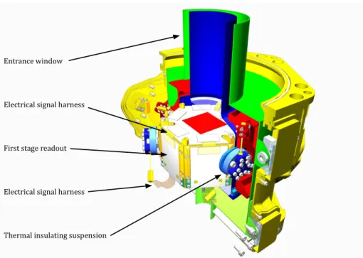
The focal plane assembly provides the thermal and mechanical support to the sensor and the anti-coincidence detector.25 In addition it accommodates the cold electronics and provides the appropriate magnetic shielding. A
magnetic field attenuation of at least∼ 105has to be achieved by two shields: a super conducting Nb shield and
a cryo-perm shield at 2 K and by an appropriate cooling sequence to avoid the trapping of magnetic flux. The focal plane assembly requires two optical blocking filters to reject the thermal and IR load on the detector.26 The current best estimate for the mass of the focal plane assembly considering design maturity margins is about 8 kg.
Outside the cryostat, a filter wheel assembly will include additional filters to further reduce the optical load on the detector for the observation of optically bright sources and to reduce the count rate in the X-rays to prevent degradation of the energy resolution. In addition the filter wheel will be equipped with a closed position, possibly a thick Be filter. The filter wheel shall also support several electrically controlled calibration sources, as needed to correct for gain drifts in the detector (the exact location of the calibration source will be subject to further studies).
Electrical)signal)harness
Thermal)insulating)suspension First)stage)readout
Electrical)signal)harness Entrance)window
Figure 5. 3D drawing of the focal plane assembly, heritated from SAFARI/SPICA.25The outer shield is at 2 K. Between
the detector, which is at 50 mK and the outer shield there is an intermediate radiation shield at 0.3 to 0.6 K. The temperature stage is also used to thermally anchor the wiring. The electronics (SQUIDs, filters etc) may be mounted on the side walls of the focal plane assembly to enable a compact design (white surfaces).
2.3 Cooling chain
The detector needs to be cooled and this requires a cryochain composed of several coolers and several intermediate temperature stages. This has been extensively studied for IXO and different designs have been proposed which can meet the requirements for Athena.27, 28 An ADR-Sorption cooler is the baseline for the last stage cooler (from 2 K to 50 mK) whereas for the other stages a number of different options can be considered (2 K Joule-Thomson (JT) cooler, Stirling coolers, 15 K pulse tube coolers). The design of the cooling chain is fully redundant and allows for the failure of a single mechanical cooler. The only exception is the last stage cooler which does not contain any movable part. The full cooling chain, including the redundant coolers and considering the design maturity margins, is expected to weight around 120 kg.
Figure 6. Left) X-IFU proposed cooling chain comprises a combination of a small passive radiator, 15 K pulse tube coolers, 2 K Joule Thomson loops and a 50/300 mK hybrid cooler. Right) 50 mK Cooler (1 µW @ 50 mK and 10 µW @ 300 mK, 77% duty cycle efficiency) developed and qualified in the framework of an ESA TRP for IXO.
Table 2. X-IFU mass, power and telemetry current best estimates including the design maturity margins.
Parameter Current best estimate Mass of the FPA 8 kg
Mass of the cryo cooler chain 120 kg Mass of the X-IFU 577 kg Power consumption of the X-IFU 1 290 W Telemetry rate (10 mCrab) ∼50 kbit/sa
aEquivalent to 4.4 Gbit/day, to be compared with the ∼100 Gbit/day available telemetry rate.
3. X-IFU PERFORMANCE ESTIMATES
In this section, we present our current best performance estimates of the X-IFU capabilities, in comparison with the requirements of Table 1.
3.1 Spectral resolution
The most recent results obtained with Frequency Domain readout are shown in Fig. 7. The pixel under test is a X-ray microcalorimeter from an array developed at GSFC with a demonstrated energy resolution of 2.3 eV at 6 keV under DC bias.29, 30 On the left side of Fig. 7 the X-ray spectrum of a 1.3 MHz AC-biased pixel is shown.
The best single pixel X-ray energy resolution measured so far was 3.6 eV.31 This resolution was consistent with the baseline resolution calculated from the detector noise and it was limited by the SQUID readout noise. On the right sight of Fig. 7, we show the NEP of a pixel biased at 2.5 MHz with an improved read-out scheme. For comparison, the NEP spectra of the DC biased and the 1.3 MHz AC-biased pixels are also shown in the plot. The baseline resolution calculated from the NEP spectra of Fig. 7 corresponding to 2.5 MHz is 2.7 eV.
Holtzer()it:(ΔE=(3.6(eV AC(biased:(1.3(MHz Cou nt s/ bin 0 50 100 150 200 Energy((keV) 5860 5880 5900 5920 DC:$ΔE=$2.3$eV AC$(2.5$MHz):$ΔE=$2.7$eV AC$(1.3$MHz):$ΔE=$3.6$eV NE P$ (W /Hz ;1 /2) 10−17 10−16 Frequency$(Hz) 100 1000 10000
Figure 7. Left: measured X-ray resolution (Fe55) for a pixel biased under AC (1.3 MHz). Right: Noise Equivalent Power (NEP) for an AC bias pixel at 2.5 MHz with improved readout (Red curve). Estimated baseline resolution is 2.7 eV. For comparison, the NEP spectra of the 1.3 MHz biased pixel (∆E = 3.6 eV) and the DC biased pixel (∆E = 2.3 eV) are shown by the blue and black lines respectively.
3.2 Particle background rejection
The implementation of an anticoincidence system is required to meet the stringent scientific requirements on the instrumental background for the X-IFU operating in a L2 orbit (see Tab. 1).20, 32 Cosmic rays and solar particles interact both directly with the detector and through the production of secondary particles in the material close
to it. A fraction of these signals falls in the energy range of the detector and cannot be disentangled from true X-ray photons. The internal particle background has been estimated using GEANT4 simulations. This was necessary since no X-ray detector has ever flown so far in an L2 orbit. However, the external flux of energetic particles at L2 was measured by several particle monitors flown on various satellites (e.g. Planck). The expected residual background without any shielding (Fig. 8, left) would be 3 counts/cm2/s,
∼60 times greater than the requirement.
With the implementation of the anticoincidence, the residual background decreases by a factor of about 10, essentially eliminating all primary particles. The residual non-rejected component is basically composed of secondary electrons. This component can be further reduced using a graded shielding with materials of a low yield for secondary electrons.33, 34 The most suited material was found to be Kapton. This shielding allows us
to meet the background requirements stated in Tab. 1.
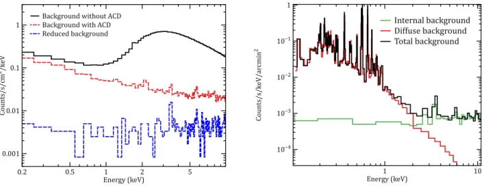
In addition to the instrumental component, the background includes an X-ray diffuse component of various origins. A diffuse X-ray emission observed in every directions is produced at high energies mostly by the unresolved emission of AGNs, and below 1 keV by line emission from hot diffuse gas in the galactic halo and the local hot bubble, with contributions from Solar Wind Charge Exchange in the 3/4 keV band. This latter component is highly variable, and a model representative of typical high galactic latitude fields had to be defined, as well as a study of its variations with time and pointing direction. Details on our modeling of these components are given in Ref. 35. The total background for X-IFU in the focal plane of Athena is plotted in Fig. 8 (right), showing that the particle background dominates only for energies above 2-3 keV.
Background+without+ACD Background+with+ACD Reduced+background Cou nt s/ s/ cm 2/k eV 0.001 0.01 0.1 1 Energy+(keV) 0.2 0.5 1 2 5 Internal(background Diffuse(background Total(background Co un ts /s /k eV /a rc mi n 2 10−4 10−3 10−2 10−1 1 Energy((keV)1 10
Figure 8. Left) The spectra of the internal background expected on X-IFU in all the cases analyzed. The black line is the expected residual background without any shielding, the red dashed line is the residual background with the implementation of the anticoincidence, and the blue dashed line is the final background level using a graded shield. Right) Background components for extended sources: the green line is the internal particle background, the red line is the diffuse component, and the total background is the black line.
3.3 Count rate capability
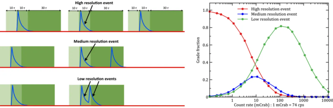
For a micro-calorimeter array the fraction of events with the highest spectral resolution depends on the rate of the incident photons.36–38 The rate in each individual pixel and therefore the fraction of high-resolution events for a given source is also determined by the shape of the mirror PSF and the relative pointing with respect to the pixels (the PSF can be centered at a pixel, just at the corner of four pixels or anywhere in between). In our simulations, conservatively, we assume that a period of 10 τ before and 40 τ after an event is necessary to achieve the maximum resolution, with a decay time of τ =150 µs (see Fig. 9). Using appropriate filtering, the mid-res events typically have a resolution of about 3.5 eV which is still very good, while the low-res event resolution will be several tens of eV, depending on count rates. In Fig. 9, the different event grades are shown as a function of
total flux on the detector and in terms of the fraction of high-res, mid-res and low-res events. As can be seen, we can easily handle sources up to 1 mCrab without noticeable degradation of the resolution. At about 10 mCrab events are split more or less equally between the three different grades.
Figure 9. Left) The classification scheme of events. Right) X-IFU count-rate capability. The fractions of the different event grades are shown as a function of the total incident photon rate on the detector (red are high-resolution, blue: medium-resolution, green: low-resolution).
3.4 Effective area
The effective area of the instrument is a combination of the effective area of the optics, folded with the detector quantum efficiency, filling factor and the transmission of the fixed optical filters in front of the detector.26 The effective area including all detector related effects are shown in Fig. 10. The X-IFU effective area around 1 keV is about 1.5 m2 and is pretty flat across the X-IFU field of view.
Athena X-IFU ASTRO-H SXS Chandra HETG XMM-Newton RGS E ff ec ti v e area (c m 2) 1 101 102 103 104 Energy (keV) 1 10
Figure 10. The X-IFU effective area, after accounting for all detector related effects (quantum efficiency, filters, filling factor, ...). The effective area of the X-IFU exceeds 1.5 m2 at 1.35 keV and is 0.25 m2 at 6.4 keV. It is compared with the ones of ASTRO-H SXS, Chandra HETG and XMM-Newton RGS. The X-IFU provides an order of magnitude improvement of effective area at 1 keV compared to the SXS. Response matrix available at http://x-ifu.irap.omp.eu, under “Resources”.
4. X-IFU STATUS AND ON-GOING TECHNOLOGY DEVELOPMENTS
Some components of the X-IFU have a TRL 4-5 based on heritage (e.g. filter wheel, instrument control unit). Focused activities in ESA member states (MS) are on-going (e.g. TES array fabrication, Cryo-AC, digital readout electronics). Taking advantage of the synergies existing between the X-IFU and the more advanced SPICA/Safari instrument (focal plane assembly, front-end electronics, digital readout electronics), most of the FEE requirements (noise floor, LC filter performance, SQUID, LNA performance, dynamic range, gain bandwidth) relevant to the X-IFU have already been met. In addition, frequency multiplexed readout has now been demonstrated for 147 sensors, and for 38 sensors without increasing the noise. As illustrated in Fig. 7, AC-biased pixels have been shown to approach the required spectral resolution. The technology developments that are required for the X-IFU are listed below:
• Demonstration of 2.5 eV resolution at 6 keV with the baseline detector system, consisting of AC-biased TES sensors with representatively dimensioned absorbers, and relevant CFEE (SQUIDs, LC filters). • Demonstration of this resolution with FDM readout of up to 40 sensors in one readout channel.
• Demonstration of the scalability of the detector and readout technology to realize the X-IFU field of view. • Development of a representative Cryo-AC detector which can be integrated into the FPA to verify the
absence of any thermal, mechanical or electrical interference.
• Demonstration of a representative focal plane assembly (TES array and Cryo-AC sensors, magnetic shield-ing, thermal suspension, cryo-harness and cold electronics).
• Development of low-noise warm analogue electronics, fast, low-power digital electronics, representative harness between the cold stage and the warm electronics, and the EMI-tight integration of these components into a cooler system.
• Optimization of basic technologies for the detector and its readout to allow for a compact and reliable design (e.g. cryo-harness).
Building a complete cooling chain is a major challenge that is being addressed by an ESA TRP, recently opened. As part of the TRP activity, integration with a representative focal plane assembly is foreseen. Emphasis will be put on the verification of the compatibility of the coolers with the detector assembly in terms of cooling power, intermediate stage intercepts, temperature profiles during cool-down/warm-up and cycling, temperature stability, micro-vibrations, EMC and magnetic fields. This activity will be phased with those aiming at building a demonstration model (DM) for the X-IFU planned for 2018, with the targeted goal of reaching TRL 5-6 at mission adoption at the X-IFU system level. Additional activities related to the development of filters are also planned.
5. CONCLUSION
The X-IFU instrument will provide unprecedented capabilities to perform spatially resolved high-resolution X-ray spectroscopy with arcsecond imaging. In view of the ambitious performance to be achieved, the X-IFU consortium is being organized. Its enabling technologies (cooling chain, sensors, readout electronics, ...) are being developed in Europe, through a coordinated technology development plan between ESA and the ESA MS. Significant progresses have been achieved in the last few years, benefiting from earlier studies and ongoing developments for SPICA/Safari. The X-IFU described above is based only on European technologies. The instrument will be built by an ESA MS consortium which has been set up within the Athena team and is led by France (IRAP, CNES), with Netherlands (SRON) and Italy (INAF) as co-leads. Specifically, CNES is proposed to be prime of the X-IFU, lead the project management, the system team and the AIT activities. Major contributions are also anticipated from Belgium, Finland, Germany, United Kingdom, Spain and Switzerland. Teams outside Europe have expressed interest in contributing to some elements of the X-IFU, for example components of the cooling chain and the focal plane assembly, and those will be considered at appropriate times by the current consortium.
ACKNOWLEDGMENTS
We wish to thank all the scientists who have helped to shape the science case defining the X-IFU requirements.
REFERENCES
[1] Nandra, K., Barret, D., Barcons, X., Fabian, A., den Herder, J.-W., Piro, L., Watson, M., Adami, C., Aird, J., Afonso, J. M., and et al., “The Hot and Energetic Universe: A White Paper presenting the science theme motivating the Athena+ mission,” 2013arXiv1306.2307N (June 2013).
[2] Willingale, R., Pareschi, G., Christensen, F., and den Herder, J.-W., “The Hot and Energetic Universe: The Optical Design of the Athena+ Mirror,” 2013arXiv1307.1709W (July 2013).
[3] Pointecouteau, E., Reiprich, T. H., Adami, C., Arnaud, M., Biffi, V., Borgani, S., Borm, K., Bourdin, H., Brueggen, M., Bulbul, E., Clerc, N., Croston, J. H., Dolag, K., Ettori, S., Finoguenov, A., Kaastra, J., Lovisari, L., Maughan, B., Mazzotta, P., Pacaud, F., de Plaa, J., Pratt, G. W., Ramos-Ceja, M., Rasia, E., Sanders, J., Zhang, Y.-Y., Allen, S., Boehringer, H., Brunetti, G., Elbaz, D., Fassbender, R., Hoekstra, H., Hildebrandt, H., Lamer, G., Marrone, D., Mohr, J., Molendi, S., Nevalainen, J., Ohashi, T., Ota, N., Pierre, M., Romer, K., Schindler, S., Schrabback, T., Schwope, A., Smith, R., Springel, V., and von der Linden, A., “The Hot and Energetic Universe: The evolution of galaxy groups and clusters,” 2013arXiv1306.2319P (June 2013).
[4] Ettori, S., Pratt, G. W., de Plaa, J., Eckert, D., Nevalainen, J., Battistelli, E. S., Borgani, S., Croston, J. H., Finoguenov, A., Kaastra, J., Gaspari, M., Gastaldello, F., Gitti, M., Molendi, S., Pointecouteau, E., Ponman, T. J., Reiprich, T. H., Roncarelli, M., Rossetti, M., Sanders, J. S., Sun, M., Trinchieri, G., Vazza, F., Arnaud, M., B¨oringher, H., Brighenti, F., Dahle, H., De Grandi, S., Mohr, J. J., Moretti, A., and Schindler, S., “The Hot and Energetic Universe: The astrophysics of galaxy groups and clusters,” 2013arXiv1306.2322E (June 2013).
[5] Croston, J. H., Sanders, J. S., Heinz, S., Hardcastle, M. J., Zhuravleva, I., Bˆırzan, L., Bower, R. G., Br¨uggen, M., Churazov, E., Edge, A. C., Ettori, S., Fabian, A. C., Finoguenov, A., Kaastra, J., Gaspari, M., Gitti, M., Nulsen, P. E. J., McNamara, B. R., Pointecouteau, E., Ponman, T. J., Pratt, G. W., Rafferty, D. A., Reiprich, T. H., Sijacki, D., Worrall, D. M., Kraft, R. P., McCarthy, I., and Wise, M., “The Hot and Energetic Universe: AGN feedback in galaxy clusters and groups,” 2013arXiv1306.2323C (June 2013). [6] Kaastra, J., Finoguenov, A., Nicastro, F., Branchini, E., Schaye, J., Cappelluti, N., Nevalainen, J., Barcons,
X., Bregman, J., Croston, J., Dolag, K., Ettori, S., Galeazzi, M., Ohashi, T., Piro, L., Pointecouteau, E., Pratt, G., Reiprich, T., Roncarelli, M., Sanders, J., Takei, Y., and Ursino, E., “The Hot and Energetic Universe: The missing baryons and the warm-hot intergalactic medium,” 2013arXiv1306.2324K (June 2013). [7] Aird, J., Comastri, A., Brusa, M., Cappelluti, N., Moretti, A., Vanzella, E., Volonteri, M., Alexander, D., Afonso, J. M., Fiore, F., Georgantopoulos, I., Iwasawa, K., Merloni, A., Nandra, K., Salvaterra, R., Salvato, M., Severgnini, P., Schawinski, K., Shankar, F., Vignali, C., and Vito, F., “The Hot and Energetic Universe: The formation and growth of the earliest supermassive black holes,” 2013arXiv1306.2325A (June 2013). [8] Georgakakis, A., Carrera, F., Lanzuisi, G., Brightman, M., Buchner, J., Aird, J., Page, M., Cappi, M.,
Afonso, J., Alonso-Herrero, A., Ballo, L., Barcons, X., Ceballos, M. T., Comastri, A., Georgantopoulos, I., Mateos, S., Nandra, K., Rosario, D., Salvato, M., Schawinski, K., Severgnini, P., and Vignali, C., “The Hot and Energetic Universe: Understanding the build-up of supermassive black holes and galaxies at the heyday of the Universe,” 2013arXiv1306.2328G (June 2013).
[9] Dovciak, M., Matt, G., Bianchi, S., Boller, T., Brenneman, L., Bursa, M., D’Ai, A., di Salvo, T., de Marco, B., Goosmann, R., Karas, V., Iwasawa, K., Kara, E., Miller, J., Miniutti, G., Papadakis, I., Petrucci, P.-O., Ponti, G., Porquet, D., Reynolds, C., Risaliti, G., Rozanska, A., Zampieri, L., Zezas, A., and Young, A., “The Hot and Energetic Universe: The close environments of supermassive black holes,” 2013arXiv1306.2331D (June 2013).
[10] Cappi, M., Done, C., Behar, E., Bianchi, S., Braito, V., Costantini, E., Dadina, M., Feruglio, C., Fiore, F., Gallagher, S., Gandhi, P., Grosso, N., Kaastra, J., King, A., Lobban, A., Maiolino, R., Piconcelli, E., Ponti, G., Porquet, D., Pounds, K., Proga, D., Ranalli, P., Reeves, J., Risaliti, G., Rodriguez Hidalgo, P., Rovilos, E., Sim, S., Stewart, G., Tombesi, F., Tsuru, T. G., Vaughan, S., Wang, D., and Worrall, D., “The Hot and Energetic Universe: Astrophysics of feedback in local AGN,” 2013arXiv1306.2330C (June 2013).
[11] Branduardi-Raymont, G., Sciortino, S., Dennerl, K., G¨udel, M., Holmstrom, M., Koutroumpa, D., Maggio, A., Micela, G., Pillitteri, I., Sanz-Forcada, J., Read, A., Bhardwaj, A., Ezoe, Y., and Gladstone, R., “The Hot and Energetic Universe: Solar system and exoplanets,” 2013arXiv1306.2332B (June 2013).
[12] Sciortino, S., Rauw, G., Audard, M., Argiroffi, C., Chu, Y.-H., De Becker, M., Drake, J., Feigelson, E., Gosset, E., Grosso, N., G¨udel, M., Guerrero, M., Herv´e, A., Kastner, J., Montez, R., Naz´e, Y., Oski-nova, L., Stelzer, B., and ud-Doula, A., “The Hot and Energetic Universe: Star formation and evolution,” 2013arXiv1306.2333S (June 2013).
[13] Motch, C., Wilms, J., Barret, D., Becker, W., Bogdanov, S., Boirin, L., Corbel, S., Cackett, E., Campana, S., de Martino, D., Haberl, F., in’t Zand, J., M´endez, M., Mignani, R., Miller, J., Orio, M., Psaltis, D., Rea, N., Rodriguez, J., Rozanska, A., Schwope, A., Steiner, A., Webb, N., Zampieri, L., and Zane, S., “The Hot and Energetic Universe: End points of stellar evolution,” 2013arXiv1306.2334M (June 2013).
[14] Decourchelle, A., Costantini, E., Badenes, C., Ballet, J., Bamba, A., Bocchino, F., Kaastra, J., Kosenko, D., Lallement, R., Lee, J., Lemoine-Goumard, M., Miceli, M., Paerels, F., Petre, R., Pinto, C., Plucinsky, P., Renaud, M., Sasaki, M., Smith, R., Tatischeff, V., Tiengo, A., Valencic, L., Vink, J., Wang, D., and Wilms, J., “The Hot and Energetic Universe: The astrophysics of supernova remnants and the interstellar medium,” 2013arXiv1306.2335D (June 2013).
[15] Jonker, P., O’Brien, P., Amati, L., Atteia, J.-L., Campana, S., Evans, P., Fender, R., Kouveliotou, C., Lodato, G., Osborne, J., Piro, L., Rau, A., Tanvir, N., and Willingale, R., “The Hot and Energetic Universe: Luminous extragalactic transients,” 2013arXiv1306.2336J (June 2013).
[16] Gottardi, L., Akamatsu, H., Barret, D., Bruin, M. P., den Hartog, R. H., den Herder, J.-W. A., Hoevers, H. F., van der Kuur, J., Jambunathan, M., and Ridder, M. L., “Development of TES-based detectors array for the x-ray integral field unit (X-IFU) on the future x-ray observatory Athena,” in this proceeding, paper 9144–93 (2014).
[17] F`abrega, L., Cam´on, A., Costa-Kr¨amer, J. L., Pobes, C., J´audenes, R., Barcons, X., Gottardi, L., den Herder, J.-W. A., and Barret, D., “Towards Mo/Au based tes detectors for Athena/X-IFU,” in this pro-ceeding, paper 9144–223 (2014).
[18] den Hartog, R. H., Gottardi, L., van der Kuur, J., van Leeuven, B.-J., van Loon, D., McCalden, A. J., den Herder, J.-W. A., Jackson, B. D., Ravera, L., Barret, D., and Cl´enet, A., “Requirements for the read-out of the detector system of ATHENA X-IFU,” in this proceeding, paper 9144–224 (2014).
[19] Den Hartog, R., Beyer, J., Boersma, D., Bruijn, M., Gottardi, L., Hoevers, H., Hou, R., Kiviranta, M., De Korte, P., Van der Kuur, J., van Leeuwen, B., Lindeman, M., and Nieuwenhuizen, A., “Frequency domain multiplexed readout of tes detector arrays with baseband feedback,” Applied Superconductivity, IEEE Transactions on 21, 289–293 (June 2011).
[20] Lotti, S., Macculi, C., Cea, D., Mineo, T., Perinati, E., Colasanti, L., Natalucci, L., and Piro, L., “Back-ground simulations for the ATHENA X-IFU instrument: impact on design and scientific performances,” in this proceeding, paper 9144–95 (2014).
[21] Gatti, F., Biasotti, M., Corsini, D., Gerone, M. D., Fumagalli, E., Pizzigoni, G., Piro, L., Barbera, M., Macculi, C., and Torrioli, G., “Fabrication and test of 50-mk large area tes based X-IFU anti-coincidence for ATHENA,” in this proceeding, paper 9144–94 (2014).
[22] Macculi, C., Piro, L., Cea, D., Colasanti, L., Lotti, S., Natalucci, L., Gatti, F., Bagliani, D., Biasotti, M., Corsini, D., Pizzigoni, G., Torrioli, G., Barbera, M., Mineo, T., Perinati, E., and Karls, E., “The cryogenic anticoincidence detector for ATHENA: the progress towards the final solution,” in this proceeding, paper 9144–226 (2014).
[23] Macculi, C., Piro, L., Colasanti, L., Lotti, S., Natalucci, L., Bagliani, D., Biasotti, M., Gatti, F., Torrioli, G., Barbera, M., Mineo, T., and Perinati, E., “The cryogenic anticoincidence detector project for athena+: An overview up to the present status,” Journal of Low Temperature Physics , 1–11 (2014).
[24] Ravera, L., Cara, C., Ceballos, M. T., Barcons, X., Barret, D., Cl´edassou, R., Cl´enet, A., Cobo, B., Doumayrou, E., den Hartog, R. H., van Leeuven, B.-J., van Loon, D., Mas-Hesse, J. M., and Pointecouteau, E., “The DRE: the digital readout electronic for Athena X-IFU,” in this proceeding, paper 9144–227 (2014). [25] van Weers, H. J., den Herder, J.-W. A., Jackson, B. D., and Kooijman, P. P., “Tes-detector based focal plane assembly key-technology developments for ATHENA and SAFARI,” in this proceeding, paper 9144–225 (2014).
[26] Barbera, M., Collura, A., Gatti, F., Cicero, U. L., Macculi, C., Piro, L., Renotte, E., and Sciortino, S., “Baseline design of the thermal blocking filters for the X-IFU detector on board ATHENA,” in this proceeding, paper 9144–228 (2014).
[27] Duband, L., Charles, I., and Duval, J.-M., “Cooler developments for the Athena cryogenic chain,” in this proceeding, paper 9144–230 (2014).
[28] Branco, M. and Charles, I., “ATHENA x-ifu detector cooling chain,” in this proceeding, paper 9144–229 (2014).
[29] Iyomoto, N., Bandler, S. R., Brekosky, R. P., Brown, A.-D., Chervenak, J. A., Finkbeiner, F. M., Kelley, R. L., Kilbourne, C. A., Porter, F. S., Sadleir, J. E., Smith, S. J., and Figueroa-Feliciano, E., “Close-packed arrays of transition-edge x-ray microcalorimeters with high spectral resolution at 5.9 keV,” Applied Physics Letters 92, 013508 (Jan. 2008).
[30] Gottardi, L., Adams, J., Bailey, C., Bandler, S., Bruijn, M., Chervenak, J., Eckart, M., Finkbeiner, F., Hartog, R., Hoevers, H., Kelley, R., Kilbourne, C., Korte, P., Kuur, J., Lindeman, M., Porter, F., Sadlier, J., and Smith, S., “Study of the dependency on magnetic field and bias voltage of an ac-biased tes mi-crocalorimeter,” Journal of Low Temperature Physics 167(3-4), 214–219 (2012).
[31] Akamatsu, H., Gottardi, L., Adams, J., Bandler, S., Bruijn, M., Chervenak, J., Eckart, M., Finkbeiner, F., den Hartog, R., Hoevers, H., Kelley, R., Kilbourne, C., van der Kuur, J., van den Linden, A. J., Porter, F., Sadleir, J., Smith, S., and Kiviranta, M., “Performance of TES X-ray Microcalorimeters with AC Bias Read-Out at MHz Frequencies,” Journal of Low Temperature Physics (Feb. 2014).
[32] Perinati, E., Santangelo, A. E., and Tenzer, C., “The background simulations for ATHENA: sources of charged particles at L-2 and the influence of solar conditions,” in this proceeding, paper 9144–232 (2014). [33] Lotti, S., Perinati, E., Natalucci, L., Piro, L., Mineo, T., Colasanti, L., and Macculi, C., “Estimate of the
impact of background particles on the x-ray microcalorimeter spectrometer on{IXO},” Nuclear Instruments and Methods in Physics Research 686(0), 31 – 37 (2012).
[34] Lotti, S., Perinati, E., Natalucci, L., Piro, L., Mineo, T., Colasanti, L., Macculi, C., Federici, M., and Martino, B., “An efficient method for reducing the background of microcalorimeters applied to ATHENA-XMS,” in [SPIE Conference Series ], 8443 (Sept. 2012).
[35] Lotti, S., “The X-IFU background,” in [Tech. Doc.: IAPS-XIFU-TN-2013-002 ], (2013).
[36] den Herder, J. W., Kelley, R. L., Mitsuda, K., Piro, L., Bandler, S. R., Bastia, P., Boyce, K. R., Bruin, M., Chervenak, J. A., Colasanti, L., Doriese, W. B., Dipirro, M., Eckart, M. E., Ezoe, Y., Figueroa-Feliciano, E., Ferrari, L., Fujimoto, R., Gatti, F., Gendreau, K. C., Gottardi, L., den Hartog, R., Hilton, G. C., Hoevers, H., Irwin, K. D., Ishisaki, Y., Kashani, A., Kilbourne, C. A., de Korte, P., van der Kuur, J., Macculi, C., Mineo, T., Nieland, J. H., Ohashi, T., Paltani, S., Perinati, E., Porter, F. S., Shirron, P. J., Smith, S. J., Takei, Y., Tashiro, M., Torrioli, G., Tsujimoto, M., van Weers, H., and Yamasaki, N. Y., “The x-ray microcalorimeter spectrometer onboard of IXO,” in [SPIE Conference Series ], 7732 (July 2010).
[37] den Herder, J. W., Bagnali, D., Bandler, S., Barbera, M., Barcons, X., Barret, D., Bastia, P., Bisotti, M., Boyce, K., Cara, C., Ceballos, M., Corcione, L., Cobo, B., Colasanti, L., de Plaa, J., DiPirro, M., Doriese, W. B., Ezoe, Y., Fujimoto, R., Gatti, F., Gottardi, L., Guttridge, P., den Hartog, R., Hepburn, I., Kelley, R., Irwin, K., Ishisaki, Y., Kilbourne, C., de Korte, P. A. J., van der Kuur, J., Lotti, S., Macculi, C., Mitsuda, K., Mineo, T., Natalucci, L., Ohashi, T., Page, M., Paltani, S., Perinati, E., Piro, L., Pigot, C., Porter, F. S., Rauw, G., Ravera, L., Renotte, E., Sauvageot, J.-L., Schmid, C., Sciortino, S., Shirron, P., Takei, Y., Torrioli, G., Tsujimoto, M., Valenziano, L., Willingale, D., de Vries, C., van Weers, H., Wilms, J., and Yamasaki, N. Y., “The x-ray microcalorimeter spectrometer onboard Athena,” in [SPIE Conference Series ], 8443 (Sept. 2012).
[38] Wilms, J., Barret, D., Beuchert, T., Brand, T., den Herder, J.-W. A., Kreykenbohm, I., Lotti, S., Nandra, K., Piro, L., Rau, A., Schmid, C., Smith, R. K., Tenzer, C., Wille, M., and Willingale, R., “Athena end-to-end simulations,” in this proceeding, paper 9144–231 (2014).