Controlled flow of smart powders
G. Lumay and N. VandewalleGRASP, Département de Physique, Université de Liège, B-4000 Liège, Belgium
!Received 24 April 2008; revised manuscript received 22 September 2008; published 29 December 2008" The flow properties of powders are mainly due to the interplay of cohesive forces and intergrain frictional forces. We have experimentally investigated a “smart granular system” for which the interparticle cohesion can be tuned by a magnetic field B!. We show that the rheological features of such a system can be controlled. Indeed, the granular flow can be controlled or even stopped by the magnetic field. Depending on the orientation of B!, different dynamical regimes can be obtained like a “dry liquid state” forming conical droplets as well as a “layered soft state.” Scaling laws are given for the flow rate outside a funnel as a function of B and for the stopping threshold of the flow as a function of the funnel output diameter D. From this analysis, it appears that the flowing properties are related to the dimensionality of the magnetic aggregates.
DOI:10.1103/PhysRevE.78.061302 PACS number!s": 81.05.Rm, 81.20.Ev
Over the last decades, granular matter has been the sub-ject of numerous studies in the physics community#1–3$, but fine cohesive powders have been studied fundamentally for only a few years#4$ despite their major economical impact on most industries. A better fundamental knowledge of their properties is required for their manipulation, in particular within the recent development of nanopowder technology. Indeed, cohesive forces are known to strongly affect the flow properties of fine powders, since they induce the formation of large aggregates. In order to avoid jamming#5–7$, flowing intermittences, and phase segregation, the methods used in industrial processes are mainly empirical ones.
In order to study the influence of the cohesive forces on the properties of granular assemblies, several methods can be used. For example, one may change the size of the particles #4$. However, controlling the size and the shape of particles is a difficult task in particular for small cohesive objects. Liquid bridges can also be used to increase the interparticle forces#8$. However, the presence of a liquid results in lubri-cation effects#9$ in addition to cohesive forces.
The idea of our study is the use of ferromagnetic particles subjected to an external magnetic field B!. Then the interpar-ticle force can be tuned continuously by varying the strength of the field. This technique has previously been used to study the influence of the cohesion on clusterization #10$, on the packing fraction #11,12$ and on the avalanche angle #13$ of granular assemblies. In this paper, we study the influence of the cohesive forces on the powder flow through the outlet of a silo. The influence of the asymmetry induced by the exter-nal field on the flow has also been studied.
When subjected to a magnetic field B, each ferromagnetic particle becomes a magnetic dipole with a magnetic moment
!!. We assume that the magnetic moments!! are parallel to the applied magnetic field B!. This is an approximation when we consider many interacting particles. The potential energy
Uij between two magnetic dipoles i and j separated by a distance rij!see Fig.1" is given by
Uij=!0! 2 4"
1 − 3 cos2#
rij3 , !1"
where # denotes the angle between the vector r!ij and the magnetic field B!. As illustrated in Fig. 1, the potential is
attractive when #$55° and repulsive when 55° $#$90°. These interactions between the particles are expected to change significantly the internal structure of the packing and the force network. Due to the directional nature of the force acting between dipoles, anisotropic particle aggregates are expected to form along the field direction. Those clusters will be observed in the following.
Our ferromagnetic powder presents similarities with fer-rofluid systems. The presence of internal structures aligned along the magnetic field changes the rheological properties of a ferrofluid. Since the term “smart fluid” !SF" is com-monly used to denote magnetorheological liquids #14$, we called our system a “smart powder” !SP". However, strong differences exist between SPs and SFs. The presence of the surrounding fluid!the air" does not play a crucial role inside the bulk of a SP. Moreover, due to the highest packing frac-tion, the contact and magnetic interactions between the grains are strongest in a SP. The differences and similarities will be discussed in this paper.
The experimental setup is illustrated in Fig. 2. A funnel with an output diameter D is placed between two magnetic
FIG. 1. !Color online" !a" Interactions between two ferromag-netic particles in a magferromag-netic field B!. The !! vector denotes the magnetic dipole induced by the magnetic field B!, and r! denotes theij
vector between the dipoles.!b" The magnetization of two ferromag-netic particles in a vertical magferromag-netic field induces repulsive interac-tion when r! is perpendicular to B! and attractive interaction whenij
r! is parallel to B!.ij
PHYSICAL REVIEW E 78, 061302!2008"
coils which are in a Helmholtz configuration. The diameter
D of the funnel can be tuned between 4 and 11.5 mm. The average grain size is d=100!m with a high polydispersity of about 50%. The whole device is made with nonmagnetic materials. In this way, the particle-wall interaction is un-changed when the strength of the magnetic field is varied. The magnetic field could be assumed to be nearly uniform in the center of the system, i.e., around the funnel. The coils are placed either vertically or horizontally !see two configura-tions in Fig. 2". We note B% when the magnetic field is
par-allel to gravity while B!denotes a horizontal magnetic field. We have explored only the range 0%&B%,B!'%100 G. We assume that in this range of magnetic field strength, the par-ticle magnetization is linear, i.e.,!(d3B. The funnel is first blocked from below with a plate. The current is injected in the coils for producing either B%or B!and the funnel is filled with a well-defined amount m=190 g !65 cm3" of iron
par-ticles. A new sample of powder is used for each measument in order to avoid memory effects due to magnetic re-manence. At time t=0, the plate blocking the funnel is rapidly removed and the grains start to fall. A laser beam crosses the flow of powder just below the funnel and a pho-todiode measures the time T needed to empty the funnel and the intermittency I of the free flow. The average flow rate is estimated through a dimensionless parameter T0/T where T0 is the funnel discharge time for B=0. The intermittency I is defined as the number of dense blocks intersecting the laser beam in the process. A continuous flow is expected to give
I=1, while an intermittent flow will provide much higher I values.
To obtain a relationship between the magnetic field strength and the intergrain interactions, a monolayer of grains has been glued onto a plate made with a nonmagnetic material. This plate has been approached to a pile for differ-ent values of the magnetic field B. For B&10 G, we observe the formation of grain chains between the pile and the plate. Therefore, the cohesion forces between the grains become higher than the gravity forces for B&10 G.
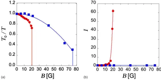
Figure3!top" presents the flow rate T0/T as a function of the magnetic field in both configurations for an output diam-eter D=8 mm. When the magnetic field increases, the inter-particle cohesion strengthens. In both configurations, the flow rate decreases along a parabolic function of B !see curve fits in Fig.3". That behavior is expected in smart fluids #15$ since the interaction energy between magnetic dipoles increases as the square of the magnetic field strength. For stronger magnetic fields, the flow rate is observed to vanish abruptly above a threshold which depends strongly on the field orientation and on the diameter D of the outlet. Since the nature of the forces depends on the field orientation and the anisotropy of the particle aggregates, the critical values
B%cand B!c are different. The fact that B!c is higher than B%c
shows that the blocking mechanism in SPs is different from FIG. 2. !Color online" Sketch of the experimental setup in two
different configurations. !Left" The powder flow driven by gravity is perpendicular to the magnetic field produced by vertical Helm-holtz coils.!Right" The powder flow driven by gravity is parallel to the magnetic field produced by horizontal Helmholtz coils. In both configurations, the intermittency of the flow is observed with a laser beam and a photodiode.
(b) (a)
FIG. 3. !Color online" !Left" Normalized flow rate T0/T as a function of the applied magnetic field. Both configurations are illustrated !dots for B%and squares for B!". Data represent averages over five experiments. The output diameter is fixed to D=8 mm. Error bars !not shown" have roughly the size of the symbols used in the figure. Below the critical point, data are fitted using a parabolic curve T0/T=1 −!B/Bc,fit" with B
%
c,fit=39.9'0.6 G and B !
c,fit=88.4'0.9 G.!Right" The intermittency I as a function of the magnetic field, using the same code. When the magnetic field is parallel to the gravity, a strong intermittency of the flow is observed near the critical point. The lines linking the experimental points are a guide for the eyes.
G. LUMAY AND N. VANDEWALLE PHYSICAL REVIEW E 78, 061302!2008"
the blocking mechanism observed in SFs. Indeed, with SFs, the closer the magnetic field to the transverse orientation, the higher the hydraulic resistance #17$. The physical mecha-nisms blocking the flow will be discussed below. The inter-mittency I is also shown in Fig. 3. While the intermittency diverges at B%c, it remains reduced below B!c, i.e., the flow is not interrupted. The intermittency expected near blockage is suppressed when using a perpendicular field.
Figure4shows the critical values of the magnetic field B%c
and B!c for different values of the funnel output diameter D. To perform the measurement of Bc, the funnel is filled with 65 cm3of powder, the plate blocking the output of the funnel is removed, and the current in the coils increased until the blocking of the flow. It should be noted that this method underestimates the critical fields if we compare to the values obtained from a fit of the entire curve of T0/T as a function of B !see Fig. 3". The evolution of both B%c and B!c as a function of the output diameter D is well fitted by a linear law. This is unexpected with respect to the parabolic behav-ior of the flux found in Fig.3and the quadratic form of the cohesion #Eq. !1"$. We propose below some physical argu-ments for describing this linearity. A strong anisotropy should also be underlined since the ratio between the critical values reaches roughly B!c /B
%
c)4.
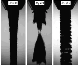
In order to visualize the anisotropy between the blocking processes as a function of the magnetic field direction, the Fig. 5 shows pictures of the flow outside the funnel for B =0, B%slightly inferior to B%c, and B!slightly inferior to B!c. When B=0!Fig.5, left", the flow is continuous for that out-let diameter !D=8 mm". A weak flow focusing behavior is observed, probably due to the interaction between moving grains and air. The grains reach the limit velocity after a few centimeters of free fall. Then, the interaction with the air plays a role. When B is parallel to the gravity!Fig.5, center", we observe the formation of “dry droplets.” Indeed, large structures having a conical shape are seen. The size and the shape of these droplets are more or less reproducible. To illustrate this size reproducibility, the Fig. 6 presents a dis-tribution of the ratio between the estimated volume V of the droplets and the average volume *V+. The volume of the
droplets is measured by image analysis. The fluctuations of the droplet size is roughly 10%. The time between two suc-cessive droplets is quasiperiodic. For B%=18 G and D
=8 mm, the average time between two droplets is 0.55 s. The small spikes observed at the surface of the droplets show that the size of the magnetic aggregates is smaller than the size of the droplets. When B is perpendicular to gravity!Fig.
5, right", the flow is layered. A few centimeters after the output, the layers are separated due to the gravitational ac-celeration. Clusters look like planar sheets having the size of the funnel output. The layers are parallel to the field. In this case, the typical size of the magnetic aggregates is limited by the funnel output diameter D. No flow focusing is observed due to the aggregates. The perpendicular magnetic field sup-presses the intermittency observed in the previous case. FIG. 4. !Color online" Critical values of the magnetic field B%c
and B!c for different values of the funnel output diameter D. Error
bars are indicated. A linear behavior is fitted.
FIG. 5. Three pictures of the granular flow for different situa-tions.!Left" The cohesiveless case !B=0". !Center" The magnetic field!B%=18 G" is parallel to gravity and the clusters are seen to be
vertical and needlelike. A dry droplet, having a nearly conical shape, is observed to fall free. !Right" The magnetic field !B! =43 G" is perpendicular to the gravity and the clusters are orga-nized such that a horizontal layered structure is seen in the flow.
FIG. 6. Distribution of the ratio between the volume V of the detected droplets and the average volume*V+ for an output diameter D=8 mm. The magnetic field B=18 G is parallel to the gravity and is slightly inferior to B%c.
CONTROLLED FLOW OF SMART POWDERS PHYSICAL REVIEW E 78, 061302!2008"
Let us propose physical arguments to link the above ob-servations and the linear behavior of Fig. 4. Two cases should be distinguished due to the orientational nature of the interactions. When the magnetic field is perpendicular to gravity and reaches the critical value B!c, the magnetic field induces the formation of aggregates with a characteristic length ( limited by the size of the output diameter D. The competition between the aggregation forces derived from Eq. !1" and gravity reads
!0!2
r4 ( mg. !2"
In this case, the distance r is the characteristic size( of the aggregates. If we assume that the clusters have a dimension-ality),!(()Band m(()*, where*is the volumic mass of the grains. Then, one has
!0!()B!c"2
(4 ((
)g*. !3"
Scaling arguments imply )=2 for a linear behavior!Fig.4" when (=D. This nontrivial dimensionality ) for magnetic aggregates has been previously obtained with magnetic diffusion-limited aggregation #16$. These simple arguments prove that the clusters induced by dipole-dipole interactions in the flow have particular anisotropic properties, emphasiz-ing the complexity of the behavior we observed.
When the magnetic field is parallel to the gravity and reaches the critical value B%c, the magnetic field induces the
formation of dry droplets with a characteristic size +. We assume that the cohesion energy U plays a role at the scale of the grain size. From Eq.!1", the intergrain cohesion per sur-face area is ,=U/d2=!
0B2d. Then, if we compare the po-tential energy of the droplet and the cohesion energy of a droplet at the outlet, we obtain
mg+( D2,. !4"
The size of these droplets is limited by the output diameter
D. Then, one has
*D4g( D2!
0!B%c"2d, !5"
leading to a linear relationship between the vertical critical magnetic field strength and the output diameter D. This simple scaling analysis is in agreement with our measure-ments!see Fig.4".
With SFs, the highest hydraulic resistance corresponds to a perpendicular orientation of the magnetic field with the flux #17$. With SPs, we observe the highest resistance to the flow when the magnetic field is parallel to the flux, i.e., parallel to gravity. This difference is probably due to the difference of the packing fraction and to the properties of the force net-work inside the system. Indeed, the packing fraction of a SP is typically-(0.6 and the packing fraction of a SF is around
-(0.3 #17$. Thus, the magnetic force network and the con-tact network inside the SP are much denser. Moreover, the geometries of these networks are probably different. This study gives a perspective for future work.
In summary, we have discovered remarkable flow proper-ties for magnetic powders. The flow rate could be stopped and the intermittency could be suppressed using the right orientation of the applied magnetic field. Cohesive forces are able to strongly change the rheological features of the pow-der so that it can flow like a dry liquid, forming droplets in some conditions. We expect similar behaviors with the use of an electric field applied to dielectric particles. More gener-ally, our analysis is applicable for all granular systems where dipole interactions modify the flowing properties. Since most particles in applications can be either polarized or magne-tized, our various findings open new perspectives in science and in industry.
G.L. would like to thank FNRS for financial support. This work has been supported by the INANOMAT project!Grant No. IAP P6/17" of the Belgian Science Policy. The authors thank C. Becco, F. Boschini, S. Dorbolo, H. Caps, F. Ludewig, O. Gerasimov, and E. Mersch for valuable discussions.
#1$ P. G. de Gennes, Rev. Mod. Phys. 71, S374 !1999". #2$ H. M. Jaeger and S. R. Nagel, Science 255, 1524 !1992". #3$ A. Kudrolli, Rep. Prog. Phys. 67, 209 !2004".
#4$ A. Castellanos, J. M. Valverde, A. T. Pérez, A. Ramos, and P. K. Watson, Phys. Rev. Lett. 82, 1156!1999".
#5$ I. Zuriguel, A Garcimartín, D. Maza, L. A. Pugnaloni, and J. M. Pastor, Phys. Rev. E 71, 051303!2005".
#6$ E. Kolb, J. Cviklinski, J. Lanuza, P. Claudin, and E Clément, Phys. Rev. E 69, 031306!2004".
#7$ G. Lumay, N. Vandewalle, C. Bodson, L. Delattre, and O. Gerasimov, Appl. Phys. Lett. 89, 093505!2006".
#8$ A. Kudrolli, Nature Mater. 7, 174 !2008".
#9$ Q. Xu, A. V. Orpe, and A. Kudrolli, Phys. Rev. E 76, 031302
!2007".
#10$ D. L. Blair and A. Kudrolli, Phys. Rev. E 67, 021302 !2003". #11$ G. Lumay and N. Vandewalle, New J. Phys. 9, 406 !2007". #12$ A. J. Forsyth, S. R. Hutton, C. F. Osborne, and M. J. Rhodes,
Phys. Rev. Lett. 87, 244301!2001".
#13$ A. J. Forsyth, S. R. Hutton, M. J. Rhodes, and C. F. Osborne, Phys. Rev. E 63, 031302!2001".
#14$ M. Whittle and W. A. Bullough, Nature !London" 358, 373 !1992".
#15$ R. Stanway, Mater. Sci. Technol. 20, 931 !2004".
#16$ N. Vandewalle and M. Ausloos, Phys. Rev. E 51, 597 !1995". #17$ P. Kuzhir, G. Bossis, V. Bashtovoi, and O. Volkova, J. Rheol.
47, 1385!2003".
G. LUMAY AND N. VANDEWALLE PHYSICAL REVIEW E 78, 061302!2008"