Pour obtenir les grades de
DOCTEUR EN SCIENCES DE L’ING ´ENIEUR
DE L’UNIVERSIT ´E DE LI `EGE
et de
DOCTEUR DE L’UNIVERSIT ´E GRENOBLE ALPES
pr´epar´ee dans le cadre d’une cotutelle entre
l’Universit´e Grenoble Alpes et
l’Universit´e de Li`ege
Pr´esent´ee par
Pierre-Yves OLU
pr´epar´ee au sein du Laboratoire d’ ´Electrochimie et de Physicochimie des Mat´eriaux et Interfaces (Grenoble)
et du Department of Chemical Engineering (Li`ege) dans l’ ´Ecole Doctorale I-MEP2 (Grenoble)
et le Coll`ege Doctoral en Chimie Appliqu´ee (Li`ege)
´Etude de l’anode pour la pile `a
com-bustible directe aux borohydrures
Th`ese soutenue publiquement le 29 Octobre 2015, devant le jury compos´e de :
Monsieur, Jean-Pierre PETIT
Professeur, Universit´e Grenoble Alpes, Pr´esident
Monsieur, Christophe COUTANCEAU
Professeur, Universit´e de Poitiers, Rapporteur
Monsieur, Umit DEMIRCI
Professeur, Universit´e de Montpellier, Rapporteur
Monsieur, Renaut MOSDALE
Docteur, PaxiTech, Examinateur
Monsieur, Marian CHATENET
Professeur, Universit´e Grenoble Alpes, Promoteur
Madame, Nathalie JOB
The present work focuses on direct borohydride fuel cell (DBFC) anodes. A first approach to develop a suitable anode design for the DBFC consists in the study of the anode within the real DBFC system. In that frame, carbon-supported platinum and palladium nanoparticles are characterized and compared as anode electrocatalyst in DBFC configuration. Other variables such as the morphology of the anode and the stability of the catalyst nanoparticles are considered. The ideal DBFC anode catalyst should show a suitable electrocatalytic activity towards the borohydride oxidation reaction (BOR), without quantitative production/escape of gaseous hydrogen during the reaction. Studying these aspects is not straightforward using a real DBFC system, as the global behavior of the DBFC depends on numerous experimental variables exter-nal to the anode. In order to overcome this issue, a prospective anode catalyst can be isolated and specifically studied in half-cell configuration in a more controlled environment. The different methods possible for the evaluation of an electrocatalyst for the anode of the DBFC are discussed in this work, and benchmarks are proposed to compare a given material with the DBFC literature. Another strategy to develop suitable DBFC anode catalysts is to further understand the BOR mechanism. In that frame, the BOR is studied on model platinum-based electrodes with different levels of complexity. Bulk polycrystalline and single-crystals Pt flat electrodes enable to study the structure sensitivity of the BOR. The poisoning of the Pt active surface is investigated using Pt nanoparticles supported on flat glassy carbon substrate. Three-dimensional electrodes are also surveyed: Pt nanoparticles supported on vertically-aligned carbon nanofiber electrodes. The deposition of various amounts of Pt nanoparticles on the VACNF substrate enables to study the influence of the density of Pt active sites towards the BOR. The findings obtained using these model electrodes are gathered with previous results from the literature in order to propose a BOR mechanism on Pt. This mechanism is used in a mean-field microki-netics model. The simulated curves of this mechanism reproduce the main experimental features.
de la DBFC est d’´etudier cette anode `a l’int´erieur du syst`eme global de la DBFC. Dans cette optique, des anodes compos´ees des catalyseurs Pt/C et Pd/C ont ´et´e caract´eris´ees en banc de test DBFC. D’autres facteurs ont aussi ´et´e ´etudi´es, tels que la morphologie de l’anode et la stabilit´e des nanoparticules des catalyseurs.
Le catalyseur d’anode de la DBFC doit id´ealement exhiber une activit´e catalytique suffisante pour la r´eaction d’oxydation des borohydrures (BOR), tout en minimisant la production et l’´echappement d’hydrog`ene gazeux durant la BOR. Ces aspects sont relativement difficiles `a ´etudier en raison des nombreuses variables ne d´ependant pas de l’anode dans un syst`eme DBFC r´eel. Une solution `a ce probl`eme consiste `a isoler l’anode de la DBFC et de l’´etudier en configuration demi-pile, avec un environnement d’´etude mieux contrˆol´e. Les diff´erentes m´ethodes pour ´evaluer un catalyseur d’anode de DBFC en demi-pile sont discut´ees, et des marqueurs sont propos´es pour l’´evaluation pertinente d’un catalyseur d’anode de DBFC par rapport aux r´esultats de la litt´erature.
Une autre strat´egie possible pour d´evelopper des catalyseurs ad´equats d’anode de DBFC est de mieux comprendre le m´ecanisme de la BOR. Dans cette optique, la BOR est ´etudi´ee sur des ´electrodes mod`eles `a base de platine. Chaque type d’´electrode mod`ele permet de contrˆoler un param`etre pr´ecis de la surface catalytique, menant ainsi `a diff´erentes ´etudes de la BOR. La sensibilit´e de la BOR `a la structure de surface catalytique est ´etudi´ee sur des ´electrodes massives de platine (polycristallin et monocristallin). L’empoisonnement de la surface active de Pt durant la BOR est ´etudi´e sur nanoparticules de Pt d´epos´ees sur substrat carbone vitreux plan. Des ´electrodes `a trois dimensions ont ´egalement ´et´e r´ealis´ees: nanoparticules de Pt d´epos´ees sur nanofibres de carbone verticalement align´ees. Le d´epˆot de diff´erentes quantit´e de Pt a permis d’´etudier l’influence de la densit´e en sites actifs de Pt sur la BOR. Les r´esultats obtenus sur ces ´electrodes mod`eles sont discut´es avec ceux de la litt´erature, et un m´ecanisme pour la BOR sur Pt est propos´e. Ce m´ecanisme est simul´e en utilisant une mod´elisation de micro-cin´etiques de type champs moyens. Les courbes simul´ees reproduisent les caract´eristiques majeures des r´esultats exp´erimentaux.
Contents
General introduction 1
Direct borohydride fuel cells (DBFC) . . . 3
Life cycle of sodium bohydride . . . 4
Commercial aspects of the DBFC . . . 8
Structure of the thesis . . . 13
I The anode catalyst in DBFC
17
1 Investigation of Pt and Pd as potential anode catalysts 19 1.1 Half-cell characterization at 25°C . . . 221.2 Fuel cell characterization at 25°C . . . 24
1.3 Influence of the operating temperature on the fuel cell characterization . . . 26
1.4 Influence of the anode morphology on the fuel cell characterization . . . 30
1.5 Stability of Pt/C and Pd/C anodic active layers during fuel cell operation . . . . 33
1.6 Conclusions . . . 35
2 Literature review of anode catalysts in DBFC 37 2.1 Single direct borohydride fuel cell (DBFC) configuration . . . 39
2.1.1 Influence of the anode catalyst on the performance of DBFC . . . 39
2.1.2 Experimental variables external to the choice of the anodic catalyst in DBFC configuration . . . 42
2.2 Electrocatalytic activity towards the borohydride oxidation reaction (BOR) . . . 53
2.2.1 Rotating disk electrode (RDE) configuration . . . 53
2.2.2 Chronopotentiometry (CP) and chronoamperometry (CA) . . . 61
2.3 Hydrogen generation and escape during the BOR . . . 62
2.4 Stability of the anode catalyst upon DBFC operation . . . 73
2.5 Summary . . . 74
II Study of the borohydride oxidation reaction (BOR)
mecha-nism on Pt
77
3 Bulk platinum 81 3.1 Polycrystalline Pt . . . 833.2 Single crystal Pt . . . 88
4.2 Poisoning of the Pt surface during the borohydride oxidation reaction (BOR) . . 99
4.3 Conclusions . . . 106
5 Pt nanoparticles supported on vertically-aligned carbon nanofilaments 107 5.1 Characterization of the Pt/VACNF electrodes . . . 109
5.2 Electrochemistry of the borohydride oxidation reaction (BOR) . . . 114
5.3 Conclusions . . . 121
6 Modelling of the BOR on Pt 123 6.1 Construction and variables of the model . . . 125
6.2 Simulation of the model . . . 132
6.3 Model development prospects . . . 135
6.3.1 Borohydride hydrolysis during the BOR . . . 135
6.3.2 BOR on other metal catalysts . . . 139
6.4 Conclusions . . . 141
General conclusions 143
Appendices
151
A Experimental 151 A.1 Characterizations in electrochemical cell . . . 151A.1.1 Electrochemical cell setup . . . 151
A.1.2 Preparation and synthesis of the model electrodes . . . 152
A.2 Characterizations in fuel cell configuration . . . 154
A.3 Physical characterizations . . . 156
B Stripping of the BOR ’surface poisons’ 157 C Pt/VACNF: supplementary figures 161 D BOR Modelling 165 D.1 Supplementary figures . . . 165
D.2 Approximation for the mass-transfer . . . 167
Direct borohydride fuel cells (DBFC)
The direct borohydride fuel cell (DBFC) is an alkaline fuel cell system fed with an aqueous solution of (usually sodium) borohydride. Ideally, the anodic reaction of the DBFC is the borohydride oxidation reaction (BOR), i.e. the direct and complete 8-electron oxidation of the BH−
4 anion, as proposed in Eq.1 [1, 2].
BH−
4 + 8OH− → BO−2 + 6H2O + 8e− (1)
The standard potential of the BOR (Eq.1) was calculated to be E0 = -1.24 V vs. SHE at pH =
14 [1, 3].
In practice, this ideal BOR competes with the homogeneous and heterogeneous hydrolysis reactions of BH−
4 [1, 2, 4, 5, 6], that occur within the solution or at the catalyst surface,
respectively. The complete hydrolysis of a BH−
4 anion is illustrated by the reaction proposed
below (Eq.2).
BH−
4 + 2H2O → BO−2 + 4H2 (2)
The hydrolysis reactions of BH−
4 are detrimental to the operation of a DBFC (as further
discussed in the section 2.3 of this manuscript). However, this hydrolysis is also the basic principle of another way for converting energy using sodium borohydride. Indeed, sodium borohydride can react on appropriate catalysts and produce hydrogen from the heterogeneous hydrolysis reactions (Eq.2). Homogeneous hydrolysis reactions of the sodium borohydride in the liquid phase can also occur (even in the absence of any catalytic surfaces) in acidic conditions for instance. The homogeneous hydrolysis reactions of sodium borohydride is further detailed in the next section of this introduction. This gaseous hydrogen can then be valorized, among other possibilities, as a fuel for standard proton exchange membrane fuel cells (PEMFC) [7, 8, 9, 10]. Although interesting, this field of study will not be treated in the work presented here, which only focusses on DBFC (i.e. the direct utilization of sodium borohydride as an anodic fuel for a direct liquid fuel cell).
Indig et al. [11] first suggested in the 1960s that the sodium borohydride could be a suitable fuel for a direct liquid fuel cell. It is interesting to note that, during the measurement of the polarization discharge curve of a sodium borohydride alkaline solution on a Ni anode in half-cell configuration, it was already observed that the hydrolysis reactions (Eq.2) hindered the performances of the system: ’One of the major problems encountered in the discharges was the formation of large amounts of hydrogen gas. Although the sodium borohydride solutions were quite stable on storage, in contact with the porous nickel electrodes, the solutions gassed slowly. The gassing rate increased with the electrochemical oxidation, and at a rate of 775 mA/cm2 much hydrogen was evolved. This indicated that hydrogen was formed as a product of
the electrochemical oxidation.’ [11].
When oxygen is used as the oxidant, the oxygen reduction reaction (ORR) occurs at the cathode of the DBFC (Eq.3). The standard potential of the ORR (Eq.3) is equal to 0.40 V vs. SHE at pH = 14.
In this case, the theoretical DBFC voltage is 1.64 V and the overall DBFC reaction is (Eq.4): BH−
4 + 2O2 → BO−2 + 2H2O (4)
The first characterization of a single DBFC configuration using oxygen as the oxidant was reported by Amendola et al. in 1999 [12]. The single cell was composed of an anode made of finely divided 97% Au/3% Pt particles deposited on carbon cloth held in an alkaline sodium borohydride reservoir, separated from an air-breathing cathode compartment using an anion-exchange membrane; a power density of 60 mW.cm−2 was obtained at 70°C.
Note that other types of oxidants can be used, such as hydrogen peroxide [13, 14] (in so-called direct borohydride hydrogen peroxide fuel cells, and often denoted DBPFC, DBHFC or DBHPFC). In these systems, the use of an acidic catholyte enables to raise the theoretical cell voltage up to 3.02 V when the anolyte pH is set at 14 and the catholyte pH at 0 [15]. However, the pH gradient between the two sides of the membrane-electrodes assembly (MEA) raises other practical issues of junction potential, reactant crossover and electrolyte intermixing that will not be discussed further here. Therefore, this work focuses only on DBFC using oxygen or air oxidants, thereafter simply denoted DBFC.
The sketches presented in Fig.1 summarize the working principle of the DBFC. Both cation-exchange membranes (CEM) and anion-cation-exchange membranes (AEM) have been used in order to construct DBFCs. A review of the different DBFC configurations used through the literature to characterize the system is presented and discussed in the chapter 2 of this manuscript. The AEM is theoretically the most logical choice of membrane for the DBFC. Indeed, since OH−
anions are the main charge carrier inside the AEM, the chemical balance is achieved for the AEM-DBFC (Fig.1b). On the contrary, Na+ cations are the main charge carrier inside the
CEM, causing accumulation and depletion of NaOH at the cathode (Eq.3) and the anode (Eq.1) of the CEM-DBFC, respectively (Fig.1a). The decrease of the anolyte pH upon CEM-DBFC operation leads to instability of the borohydride anion due to the enhancement of the hydrolysis rate (see the following section of this introduction), while the accumulation of NaOH at the cathode of the CEM-DBFC causes obvious practical issues such as the physical blocking of the cathode compartment. However, to the author’s knowledge, no AEM with sufficient activity in the conditions required for DBFC operation (i.e. at pH equal to or higher than 14) is currently commercially available, contrary to the already widespread Nafion® CEM. Moreover, the BH− 4
crossover rate is obviously faster using a AEM compared to a CEM, hindering the overall performances of the AEM-DBFC. This issue may be dealt with using cathode catalysts which are active for the ORR while inactive for the BOR (this discussion is further developed in the part II of this manuscript). Note that in the case of a fuel-tolerant cathode catalyst (i.e. a catalyst inactive towards the BOR in the cathode conditions upon DBFC operation), it is also possible to consider a DBFC constructed with a ’simple’ porous separator, which electrically insulates the DBFC electrodes from each other. The ionic conduction in the latter proposition of DBFC configuration is ensured by the liquid electrolyte.
Life cycle of sodium bohydride
Sodium borohydride was discovered by Schlesinger and Brown in the early 1940s. However, the work of this group was classified during wartime, so that the first publication in a scientific journal about this discovery occurred later, in 1953 [17]. The fascinating story of the discovery of sodium borohydride and its interesting properties have been humorously retold later by
Figure 1: Working principle schemes of direct borohydride fuel cells with: (a) a cation permeable membrane and (b) an anion permeable membrane, drawn to emphasize the chemical balance. Reproduced from Ref.[16] with permission from Elsevier.
Brown [18]. This group also proposed a process for the synthesis of sodium borohydride at atmospheric pressure and ca. 250°C [19]. The Brown-Schlesinger process is currently widespread in the industry in order to produce sodium borohydride [20, 21]. A schematic summary of the Brown-Schlesinger process is presented in Fig.2.
Another industrial way for producing sodium borohydride is the Bayer process, used by Bayer AG corporation [22, 23]. The Bayer process consists of a one-pot reaction at relatively high temperature (400-500°C) and under H2pressure of borosilicate glass (fused from borax and quartz
sand) with metallic sodium and hydrogen, as shown in Eq.5. The sodium borohydride/silicate mixture obtained is then extracted with liquid ammonia under pressure. A schematic summary of the Bayer process is presented in Fig.3. Note that many other processes exist [21], but are not widespread in the industry yet [20].
(Na2B4O7 + 7SiO2) + 16Na + 8H2 → 4NaBH4 + 7Na2SiO3 (5)
Borates are defined in the Oxford dictionaries as ’salts in which the anion contains both boron and oxygen, as in borax’. A photograph of borax crystals is presented in Fig.4. Turkey is the world first producer of borate, and is also considered to own the world largest borate reserve, although the detailed figures of the borate world reserve repartition do not exactly
Figure 2: Schematic of the Brown-Schlesinger process for the synthesis of sodium borohydride. Step 1: Steam reforming of methane to produce hydrogen. Step 2: Electrolysis of sodium chloride to produce sodium metal. Step 3: Refining of borax to produce boric acid. Step 4: Convertion of boric acid to trimethylborate with methanol. Step 5: Reaction of sodium metal and hydrogen to produce sodium hydride. Step 6: Combination of sodium hydride and trimethylborate to produce sodium borohydride. Step 7: Recycling of sodium methoxide by-product to methanol. Reproduced from Ref.[20].
concur, depending on which country the said studies originated from. The borate reserve of Turkey was reported to be ca. 70% and 29% of the world reserve of borate in Refs. [24, 25] and [26], respectively, whereas the borate reserve of the United States (considered as the second world largest borate reserve) was reported to be ca. 7% and 19% of the world reserve of borate in Refs. [24] and [26], respectively. The borate world reserve was estimated to be ca. 1176 and 210 millions metric tons B2O3 equivalent in Refs.[24] and [26], respectively. The world
production was estimated to be ca. 2 millions metric tons B2O3 equivalent per year for the last
decade [24, 25, 26]. The main utilization of borate is currently related to the glass fiber market. Sodium borohydride is highly soluble in water; ca. 35 g of NaBH4 per 100 g of water at 25°C
[27]. However, BH−
4 is unstable in water due to the homogeneous hydrolysis reactions (Eq.2).
It was first reported that BH−
4 hydrolysis rate increases with the increase of the acidity of the
solution [28, 29]. Although it is necessary to be able to increase the BH−
4 hydrolysis rate when
the ultimate goal is to generate gaseous hydrogen from borohydride, it is rather the contrary in the case of the DBFC where the highest chemical stability of the borohydride in the anolyte is required. In that frame, increasing the pH of the borohydride-containing solution hinders the hydrolysis reactions [1, 30]. Brown et al. [31] observed the KBH4 degradation rate to be
linearly dependent on the pH of the solution (measured for solution pH between 12 and 14). The stability of a borohydride-containing solution at given pH and temperature values can be estimated using the equation established by Mochalov et al. [32] presented below (Eq.6).
log[t1/2] = pH − 0.034T − 1.92 (6)
Where t1/2 is the half-life of BH−4 in minutes, and T is the temperature in Kelvin. According
to Eq.6, the half-life of BH−
4 at 25°C is 6.1 min, 10.2 h, 42.6 days and 426.2 days at a pH of
Figure 3: Schematic of the Bayer process for the synthesis of sodium borohydride. Tentative trans-lation of the german words: ’Schmelzofen’↔’Melting furnace’, ’Abschreckwanne’↔’Quenching tub’, ’Brecher’↔’Crusher’, ’Trockner’↔’Dryer’. Reproduced from Ref. [22] with permission from Wiley-VCH.
the stability of the borohydride. Minkina et al. [33] observed a very slow NaBH4 degradation
(less than 1% loss in NaBH4) after 50 h at 22°C for the system 27 wt.% NaBH4-10 wt.% NaOH.
However, higher temperature and lower concentration in NaOH led more severe losses in stability: ca. 70% loss in NaBH4 after 350 days at 50°C for the system 29 wt.% NaBH4-5 wt.% NaOH [33].
Note that, in this work, Minkina et al. [33] did not actually measure the hydrogen escape from the system for 350 days, but instead constructed the curve of sodium borohydride degradation from the measurement of the hydrolysis rate of several intermediate NaBH4-NaBO2-NaOH
compositions. Nevertheless, one can deduce that relatively large concentration in NaOH as well as a low temperature are required for long-time storage of borohydride-containing solutions.
The final product of the BOR is believed to be the metaborate anion BO−
2 (Eq.1). In order
to propose a sustainable DBFC, an efficient way for recycling BO−
2 back to BH−4 is required.
To the author’s knowledge, no satisfactory method mature enough for efficient recycling has emerged yet. Among other developments, Kojima et al. [34] investigated the reaction of NaBO2
to NaBH4 using Mg2Si alloy as reducing agent. A recycling yield of 98% at 550°C under 7 MPa
pressure of H2 was achieved [34]. Fig.5 shows the recycling yield of NaBO2 to NaBH4 at various
H2 pressure [34]. Note that the relatively high H2 pressure required to achieve satisfactory
recycling yields is not very practical for industrial upscaling.
A promising result was presented by Li et al. [35], where MgH2 was used as a reducing agent
to react with NaBO2 in a planetary ball mill at room temperature and pressure. The predicted
recycling reaction is detailed below (Eq.7). As shown in Fig.6, almost 100% recycling yield was obtained for a MgH2 over-stoichiometry of 1.25.
NaBO2 + 2MgH2 → NaBH4 + 2MgO (7)
Methane and coke were also considered as reducing agents for this recycling reaction [34]. However, the large positive free-energy of these reactions for temperature values below 1000°C
Figure 4: Photograph of borax crystals. Reproduced from Wikipedia: ’Borax’ english page. Public domain.
makes them thermodynamically unfavorable and thus, not sustainable at an industrial scale [20]. Another way for recycling BO−
2 is to use electrochemical technique; considering the BH−4/BO−2
half-reaction (Eq.1) to be reversible, it is theoretically possible to perform the electrolysis of BH−
4 from BO−2 [36]. Several patents and articles claimed recycling yield around 20% in aqueous
electrolyte. However, Gyenge et al. [37] did not observe any production of BH−
4 using various
methods of electrolysis presented in the past. The choice of the method for measuring the amount of borohydride produced during the electrolysis was suspected to be responsible for the erroneous results [37]. The electrolysis of BH−
4 in aqueous electrolyte does not seem very suitable,
as the standard potential of Eq.1 is out of the water electrochemical stability domain for most of the possible electrocatalysts (in other terms, H2 generation is most likely to occur rather
than the BO−
2 reduction into BH−4 at the cathode of the electrolyzer). In that frame, further
development concerning the electrolysis of BH−
4 is still possible in non-aqueous electrolytes such
as molten salts or ionic liquids [20, 21, 38]. This will not be studied in the present thesis.
Commercial aspects of the DBFC
The thermodynamic calculations performed on the overall (and ideal) DBFC reaction (Eq.4) lead to a theoretical cell voltage of 1.64 V [1, 3], which is higher than the theoretical cell voltages of the proton exchange membrane fuel cell (PEMFC: 1.23 V) and of the direct methanol fuel cell (DMFC: 1.21 V). Considering an ideal 8-electron borohydride oxidation reaction (BOR, Eq.1), the theoretical specific energy of the DBFC considering the NaBH4 compound only (i.e.
ignoring the contribution of NaOH as part of the fuel) is given by [12]: (8 e−per NaBH4)(1.64 V)(96485 A.s−1.mol−1)
(37.83 × 10⁻³kgNaBH
4.mol−1NaBH4)(3600 s.h−1)(1000)
= 9.30 kW.h.kg−1 NaBH4
This value of DBFC theoretical specific energy is higher than the DMFC theoretical spe-cific energy (6.07 kW.h.kg−1
MeOH) but lower than the PEMFC theoretical specific energy (32.71
kW.h.kg−1 H2) [39].
Figure 5: Influence of pressure on NaBH4 recycling yield from NaBO2 (reducing agents Mg2Si
or Mg, 550°C, 2 h). Reproduced from Ref.[34] with permission from Elsevier.
The main advantage of the DBFC, from the thermodynamics point of view, is its high theoretical energy density. Indeed, compared to pure hydrogen which can be either compressed or liquefied in the case of the PEMFC, sodium borohydride can be dissolved in an aqueous alkaline solution and therefore easily leads to higher theoretical energy density for the DBFC. Let us consider a practical DBFC fed with an anolyte composed of 10 wt.% NaBH4 and
20 wt.% NaOH. Given the density of this solution (1.19 g.cm−3 at room temperature [40]),
the partial specific volume of the anolyte is 8.40 L.kg−1
NaBH4 and thus the theoretical energy
density of the DBFC (considering the theoretical specific energy calculated above) is in this case 1.11 kW.h.L−1
anolyte. The same reasoning can be applied for a DMFC fed with an anolyte
composed of 2 M MeOH in water (density of 0.99 g.cm−3): the partial specific volume of
the anolyte is 15.61 L.kg−1
MeOH and the theoretical energy density of the DMFC is then 0.39
kW.h.L−1
anolyte. For the PEMFC, let us consider a tank of H2 compressed at 200 atm and
at a temperature of 298 K. A first approximation using the ideal gas law leads to a specific volume of 60.50 L.kg−1
H2, and to a theoretical energy density of 0.54 kW.h.L−1anolytefor the PEMFC.
The major current impediment to the DBFC, commercially speaking, is the high cost of sodium borohydride. Considering the current purchase cost (20 US$.kg−1
NaBH4) and the theoretical
specific energy calculated above, the NaBH4 contribution to the cost of theoretical energy for the
DBFC is 2.15 US$.(kW.h)−1. For comparison, the contributions of H2 and methanol to the cost of
theoretical energy are 0.15 and 0.66 US$.(kW.h)−1 for the PEMFC and the DMFC, respectively
(assuming purchase costs for H2 and methanol of 5 US$.kg−1H2 and 4 US$.kg−1MeOH, respectively).
In 2005, Li et al. [41] estimated the fuel contribution to the cost of electricity to be 100 times higher for NaBH4 in the DBFC compared to H2 in the PEMFC (the purchase cost of sodium
borohydride at this time was taken as 55 US$.kg−1
NaBH4). In the same paper, Li et al. [41]
esti-mated a target of 0.55 US$.kg−1
NaBH4 for the DBFC to be competitive for the automotive market.
Figure 6: NaBH4formation from NaBO2by ball milling (atmospheric temperature and pressure),
using MgH2 as reducing agent. Reproduced from Ref.[35] with permission from Elsevier.
Wee et al. [42] performed a comparative 20 W fuel cell study on DBFC and DMFC. As the energy density of the DBFC is higher than that of the DMFC (see above), and as higher values of maximum power density for the DBFC compared to the DMFC were obtained in the literature in practical conditions, the DBFC was found to lead to a smaller cell size compared to the DMFC for identical power output. Moreover, and contrary to the DMFC, it is possible to consider a DBFC that uses non-noble anode and cathode catalysts without detrimental losses of performance. Indeed, at the anode of the DBFC, the BOR can be efficiently catalyzed by non-noble electrocatalysts (Ni- or Co- based, for instance), while at the cathode of the DBFC, the oxygen reduction reaction (ORR) occurs in alkaline conditions, which enables the use of non-noble electrocatalysts for the ORR (such as MnO2 or perovskite-based electrocatalysts).
For further information, please refer to the chapter 2 of this manuscript, where a review of the different types of catalysts for the DBFC is made. In the case of the DMFC, the general low activity for the methanol oxidation reaction leads to the use of relatively high loadings of Pt-based anode catalysts [43]. As the ORR occurs in acidic conditions at the cathode of the DMFC, the use of noble catalyst such as Pt is also necessary in order to achieve sufficient performances. Considering a state-of-the-art DMFC with a peak power density of 100 mW.cm−2
using a Pt catalyst loading of 3 mgPt.cm−2, the Pt need per power output can be estimated as
30 gPt.kW−1, which is a serious drawback considering a current Pt price (35 US$.g−1Pt) and the
limited availability of the Pt ore. Therefore, Wee et al. [42] estimated the production cost of a DBFC to be lower than that of the DMFC (1.5 US$.W−1 and 5 US$.W−1 for the DBFC and
the DMFC, respectively).
Although the DBFC was estimated to be cheaper to produce compared to the DMFC, Wee et al. [42] also estimated that the relatively high cost of NaBH4 compared to methanol (see above)
makes the DBFC uneconomical for long operation duration. As shown is Fig.7, a 20 W DBFC system without any hydrolysis reaction occurring at the anode is economically competitive compared to a 20 W DMFC system as long as the fuel cells operation time does not exceed 280 h [42]. Considering the high cost of NaBH4, the fuel efficiency of the DBFC should be maximized.
This means that the non-valorized H2 escaped from the anode upon DBFC operation due to
BH−
4 hydrolysis reactions (Eq.2), as well as the BH−4 crossover from the anode to the cathode,
should be minimized in order to enhance the economical competitivity of the DBFC. Indeed, as shown in Fig.7, the cost of electricity raises when considering a 6e−-DBFC (i.e. a configuration
where only 6e− are valorized per BH−
4 anion, due the escape of one H2 per BH−4 via hydrolysis)
compared to a 8e−-DBFC (i.e. a configuration where the full 8e− are valorized per BH−
4 anion).
Figure 7: Total cost of DMFC, 8e−-DBFC and 6e−-DBFC operated at power output of 20 W
during 3000 h considering crossover; prices of fuels assumed to be 10.4 US$.kg−1
MeOH and 55
US$.kg−1
NaBH4. Reproduced from Ref.[42] with permission from Elsevier.
Considering the cost of the DBFC, there is still room for improvement. Lowering the manu-facturing cost of the DBFC requires to develop non-noble anode and cathode electrocatalysts active for the BOR (with minimum H2 escape) and the ORR, respectively. In addition, the
de-velopment of performant but cheap anion-exchange membranes (AEM) is necessary. As already mentioned, it is also possible to consider a DBFC system with a mixed-reactant electrolyte, using simply a cheap porous electrical insulator between the two electrodes. However, in the case of DBFC using an AEM or a mixed-reactant electrolyte, one should be aware that the fuel efficiency is likely to be relatively low (due to fast BH−
4 crossover rate). Thus, as the
cost of NaBH4 is a limiting step in the commercial competitivity of the DBFC, the operation
cost of these systems may be uneconomical. Considering the cost of NaBH4 production, the
most costly step in the Brown-Schlesinger and Bayer processes is the production of metallic sodium by the electrolysis of sodium chloride (step 2 in Fig.2). In order to reduce the cost of NaBH4, this step could be improved and also integrated into the production of sodium
borohydride, which would save the high cost associated to the transportation of reactive raw sodium to the production site [20]. The development of NaBO2 recycling methods would also
contribute to lower the cost of NaBH4, and improve the sustainability of the DBFC. To the
author’s opinion, the production cost of NaBH4 could be strongly reduced, if the demand for the
Besides the above considerations on cost, another drawback of the DMFC compared to the DBFC is that methanol (an organic molecule) oxidation reaction inevitably leads to the formation of adsorbed CO that poisons the Pt active surface, and ultimately of gaseous CO2.
This raises issues in the management of gas formation in a direct liquid fuel cell system [43]. However, the DBFC is likely to suffer from the same main drawback as the alkaline fuel cells (AFC), i.e. the formation of solid carbonate at the cathode side of the DBFC, coming from the reaction of the CO2 (contained in the air) with the alkaline electrolyte [44]. Moreover, the BOR
could lead to the formation of solid boron oxides such as NaBO2 (Eq.1) which might block the
anode or the cathode (considering the crossover of borohydride) of a DBFC [45]. The formation of a solid material blocking the air channels of the cathode bipolar plate is shown in Fig.8 after long-term operation of the DBFC; this solid was analyzed to be a mix of sodium borate and sodium carbonate [46].
Figure 8: Photograph of the air cathode current collector after long-term operation of a DBFC. Reproduced from Ref.[46] with permission from Elsevier.
In the light of the commercial aspects of the DBFC system discussed above, this technology could suit the market segment of low power portable applications, and be a substitute to the batteries of mobile phones, computer notebooks, etc. [41]. Indeed in this market, the high cost of NaBH4 is not an unacceptable issue: for instance, a commercial 1.4 W.h AAA Cell primary
battery costs 1.25 US$, leading to a cost of electricity of 890 US$.(kW.h)−1. Furthermore, the
great energy density of the DBFC is very attractive for this application. In that frame, the research company MERIT Ltd. (Materials and Energy Research Institute Tokyo) in conjunction with Kogakuin University (Japan) developed some DBFC prototypes for low power portable applications, as illustrated by the prototype micro DBFC of 10 W shown in Fig.9. The only once commercially available DBFC known to the author was the ’Medis 24-7 Power Pack’ developed by Medis Technology Ltd. This system was supposed to enable 5 to 6 full charges of an iPhone (see Fig.10) with a power of 4 W and a capacity of 4.5 A.h, and cost 40 US$ (the replacement pack of anolyte solution cost 20 US$). The product had a guaranteed storage time of 18 months before activation. The activation of the device occurred by squeezing the external device shell in order to connect the anolyte tank to the rest of the DBFC. Once activated, the life-time of the device was claimed to be 3 months [47]. However, Medis Technology Ltd. collapsed in 2009
[48], so that no further developments of this system have been reported since. It is unknown to the author how this system reacted to carbonation from atmospheric CO2 and to the possible
precipitation/accumulation of borates.
Figure 9: Prototype of flat-type DBFC [10W], without auxiliary devices (for experimental purposes only). Reproduced from the website of MERIT Ltd. [49].
Structure of the thesis
This study focuses on the anode of direct borohydride fuel cells (DBFC). The ideal anode for the DBFC meets the following specifications:
• Fast kinetics of the borohydride oxidation reaction (BOR) on the anode electrocatalyst. An active anode electrocatalyst towards the BOR enables low polarization potentials, leading to high overall electrical performances (e.g. high value of maximum power density) for the DBFC;
• Low H2 escape upon DBFC operation, leading to high values of fuel efficiency. The choice
of the electrocatalyst material as well as the global design of the anode can influence this parameter;
• High stability of the anode upon DBFC long-term operation; • Low cost of anode materials and anode manufacturing.
Through the literature of the DBFC systems, two different strategies are traditionally em-ployed in order to study and/or develop the anode of the DBFC. The first one is the systemic approach, which studies the anode inside the global and very complex DBFC system. A typical example for this approach would be to characterize several DBFC using different types of anodes (different electrocatalysts materials, support material, binder, etc.) under similar experimental
Figure 10: ’Medis 24-7 Power Pack’ DBFC charging a smartphone. Reproduced from the website of CNET [47]. Martin LaMonica/CNET News.
conditions, and to observe the influence of the considered variables on the overall performances of the global DBFC system (polarization curve, H2 escape rate, etc.). A study realized using the
systemic approach is very close to the real conditions of the system. However, the huge number of experimental variables (which can be strongly correlated) leads to a poor understanding of the details ruling the behavior of the system towards the variable studied. The second strategy is the analytic approach, which isolates one element of the considered system (in our case, the anode of the DBFC taken apart from the global system) and reduces this element in order to be able to control all the variables ruling its behavior. In terms of experiment, this analytic strategy is typically performed using a half-cell configuration in a three-electrode setup, where some elements of the anode are placed in a controlled environment, thereby enabling the study of few experimental variables. This approach leads to further understanding of fundamental interactions. However, the lower the number of experimental variables, the further from the reality of a practical DBFC system.
In the author’s opinion, the systemic and analytic approaches are not opposed, but rather complementary. A strategy purely based on the global systemic approach would certainly lead to a slow development of the DBFC technology, considering the huge number of interconnected experimental variables. One needs to understand, to the most detailed level accessible, the phenomena occurring during the DBFC operation in order to optimize the system in an in-telligent way. On the other hand, understanding the phenomena occurring at every separate element of the system is not sufficient: the findings on one element have to be confronted to the reality of the global system, which may behave in a way totally unexpected by the study of separate elements. In the following, let us consider a not-so-imaginary case study illustrating this complementarity between the systemic and analytic approaches, in relation to the study of the anode in the DBFC. The first study of the BOR mechanism in three-electrode electrochemical cell conditions leads to the selection and optimization of an electrocatalyst that is highly active for the BOR. A DBFC using the selected electrocatalyst is characterized in real conditions; the value of maximum power density being high, as expected. However, harsh H2 escape from the
anode is observed upon DBFC operation, hindering the fuel efficiency of the DBFC. This finding finally leads to new directions of study, such as the investigation of the influence/contribution
of the hydrolysis reaction in the BOR mechanism (further understanding of the hydrolysis mechanisms shall enable to propose new electrocatalysts which will solve this issue), or the optimization of the anode catalyst support in order to manage the gaseous hydrogen. The thesis presented here attempts to follow this philosophy of study.
The first part of this thesis studies the anode electrocatalyst in the DBFC. The chapter 1 of this first part characterizes two different DBFC configurations using either Pt/C or Pd/C as anode catalyst. The fuel cells are also fed with another type of boron-based fuel; ammo-nia borane. The characterizations of the liquid fuel cells are performed at various operating temperature, and the corresponding performances are compared. The influence of the anode macroporosity towards the performances of the DBFC is reported. The stability of the Pt and Pd nanoparticles is also evaluated using TEM imaging. In this chapter, experiments are also performed in a three-electrode electrochemical cell using either bulk polycrystalline Pt or Pd (in rotating disk electrode configuration) in alkaline sodium borohydride or alkaline ammonia borane electrolytes. Based on the results in three-electrode electrochemical cell configuration, the overall performances of the fuel cells are predicted. The chapter 2 of the first part presents a literature review of anode catalysts for the DBFC. Along with the experimental conditions used in the literature to characterize the DBFC and the corresponding performances, this chapter presents and discusses experimental variables external to the anode in the DBFC characterizations. It also reviews and discusses different methods and the corresponding results obtained in the literature to evaluate the electrocatalytic activity of several materials towards the BOR, as well as the H2 escape rate upon conditions close the DBFC operation.
The second part of this thesis investigates the BOR mechanism on platinum surfaces. Dif-ferent types of Pt-based model electrodes are used in order to achieve further understanding of the BOR mechanism. Each type of model electrode enables to control a precise variable related to the Pt electrocatalyst, and thus to study different aspects of the BOR. In chapter 3, the use of platinum in the form of bulk polycrystalline and single-crystal flat electrodes enables to study the structure-sensitivity of the BOR. More complex model electrodes are prepared and studied in chapter 4: Pt nanoparticles supported on flat glassy carbon (GC) sub-strate. In this chapter, the poisoning of the Pt active surface by BOR intermediates/products is investigated. To increase the complexity level of the model electrodes, Pt nanoparticles supported on vertically-aligned carbon nanofiber (VACNF) electrodes are prepared and char-acterized in chapter 5. The deposition of various amounts of Pt nanoparticles on the VACNF substrate enables to study the influence of the density of Pt active sites towards the BOR. Also, the release of some intermediates formed during the BOR is measured using a gold-ring rotating gold-ring-disk electrode setup. Finally, the chapter 6 gathers the findings mentioned above as well as other experimental and computational results from the literature; a tentative mechanism for the BOR on Pt is proposed. The simulated curves of this mechanism are compared with the experimental ones. Further development of this model, in order to account for the experimental observations of the first part of this thesis, is proposed and briefly discussed. The work presented in this thesis has been published (or is currently in the process of submission) in several paper articles co-authored by Pierre-Yves Olu, where all the experiments were performed or supervised by Pierre-Yves Olu.
Chapter 1 is based on: P.-Y. Olu, F. Deschamps, G. Caldarella, M. Chatenet and N. Job, ’Investigation of platinum and palladium as potential anodic catalysts for direct borohydride
and ammonia borane fuel cells’, J. Power Sources 297 (2015) 492–503.
Chapter 2 is based on: P.-Y. Olu, N. Job and M. Chatenet, ’The anode catalyst material in direct borohydride fuel cells: a review’, currently (September 2015) in the process of submission.
Chapter 3 is partly based on: P.-Y. Olu, B. Gilles, N. Job and M. Chatenet, ’Influence of the surface morphology of smooth platinum electrodes for the sodium borohydride oxidation reaction’, Electrochem. Commun. 43 (2014) 47–50.
Chapter 4 is based on: P.-Y. Olu, C. R. Barros, N. Job and M. Chatenet, ’Electrooxidation of NaBH4 in alkaline medium on well-defined Pt nanoparticles deposited onto flat glassy carbon
substrate: evaluation of the effects of Pt nanoparticle size, inter-particle distance, and loading’, Electrocatalysis 5 (2014) 288–300.
Chapter 5 and Chapter 6 are partly based on: P.-Y. Olu, A. Bonnefont, M. Rouhet, S. Bozdech, N. Job, M. Chatenet and E. Savinova, ’Insights into the potential dependence of the borohydride electrooxidation reaction mechanism on platinum nanoparticles supported on ordered carbon nanomaterials’, Electrochim. Acta (2015) In Press.
Part I
Chapter 1
Investigation of Pt and Pd as potential
anode catalysts
specifically in this chapter, another type of direct liquid fuel cell (DLFC), the direct ammonia borane fuel cell (DABFC), is also studied. The DABFC has a relatively recent history, and few studies have been carried out on the complete system. Yoa et al. [50] used Ag/C anodic catalyst in DABFC configuration, while Zhang et al. [51] used Pt/C. To the author’s knowledge, no study comparing different anodic materials for the same DABFC characterization system has been performed to date.
The anodic reaction of the DABFC is ideally the direct and complete ammonia borane oxidation reaction (ABOR). It is a 6-electron reaction, as proposed below (Eq.3) [51].
NH3BH3 + 6OH− → BO2− + NH+4 + 4H2O + 6e− (1.1)
The standard potential for the ABOR (Eq.3) was calculated to be E0 = -1.21 V vs. SHE at pH
= 14 [51]. When oxygen is used as the oxidant, the theoretical DABFC voltage is 1.61 V and the overall DABFC reaction is (Eq.4):
NH3BH3 + 32O2 → BO−2 + NH+4 + H2O (1.2)
It has also been proposed that NH3BH3 spontaneously generates BH3OH−in alkaline electrolyte,
the latter then reacting in a 6-electron oxidation reaction [52]. It is acknowledged that the ammonia moiety (NH3) is not oxidized in the ABOR: NH3 oxidation actually happens at
too high potential values to be relevant at a DABFC anode on standard catalysts [53, 54]. Note that, like the BOR, the ABOR also competes with the heterogeneous hydrolysis reactions of NH3BH3, which generates gaseous hydrogen and thus reduces the fuel efficiency of the DABFC.
In this chapter, Pt/C and Pd/C are studied as potential anodic catalysts for the DBFC and the DABFC. The electrocatalytic activities of these carbon-supported metal catalysts towards the BOR and the ABOR at 25°C are compared using the half-cell configuration. The predictive power of the half-cell experiments is evaluated and discussed by comparison with the performances obtained in the fuel cell configuration, using Pt/C and Pd/C as anodic catalysts and at an operating temperature of 25°C. DBFC and DABFC are also characterized at higher operating temperatures (60°C and 80°C), the subsequent evolution of the fuel cell performances being reported and discussed. The uncertainty around the measurement of the performances in the fuel cell configuration is highlighted by studying the great sensitivity of the experiments with regards to the morphology of the anodic active layer. Furthermore, the issue of the stability of the Pt/C and Pd/C anodic layers during DBFC and DABFC characterizations is evaluated, based on TEM observation of the catalysts before and after electrochemical experiments.
Note that the purpose of this work is to study different types of anodes for application in the DBFC and the DABFC systems, using different types of catalysts (Pt/C or Pd/C) or different morphologies. The achievement of the best possible fuel cell performances was not the primary aim, the main goal was the use of similar (and thus comparable) fuel cell configurations, with few different experimental variables which could be investigated. It is also important to note that the aim of the present chapter is not to discuss the whole mechanisms of borohydride and ammonia borane oxidation reactions on Pt and Pd, but rather to compare the electrocatalytic behaviors of these two model catalysts towards the borohydride and ammonia borane oxidation reactions, in order to explain further the different performances obtained in fuel cell configuration. Investi-gation and discussion of the BOR mechanism on Pt are developed in the second part of this thesis.
1.1 Half-cell characterization at 25°C
The electrocatalytic behavior of platinum and palladium catalysts towards the sodium borohy-dride (NaBH4) and ammonia borane (NH3BH3) electrooxidation reactions were found to differ
greatly. Cyclic voltammetries of smooth Pt and Pd characterized in rotating disk electrode (RDE) configuration (for a controlled mass-transfer) were performed in a three-electrode
electro-chemical cell. For further information concerning the experimental details, please refer to the corresponding Appendix A.1.1 of this thesis. Fig.1.1 shows the cyclic voltammograms plotted at room temperature (ca. 25°C), for a scan rate of 25 mV.s−1 and a revolution rate of 1000
rpm of smooth platinum and palladium RDE in 1 M NaOH + either 10 mM NaBH4 or 10 mM
NH3BH3. The cyclic voltammograms of Fig.1.1A show a better overall electrocatalytic activity
of the platinum electrode for the ammonia borane oxidation reaction compared to the sodium borohydride oxidation reaction at room temperature. Indeed, the open circuit potential (OCP) for the Pt electrode is slightly more negative when in contact with an electrolyte containing ammonia borane (-52 mV vs. RHE) than sodium borohydride (-24 mV vs. RHE), and the oxidation current is slightly larger for ammonia borane compared to sodium borohydride at low potential values (below 0.2 V vs. RHE). Unlike platinum, the palladium electrode displays very different electrocatalytic behaviors for sodium borohydride and ammonia borane electrooxida-tion, respectively. As presented in Fig.1.1B, the palladium electrode in contact with sodium borohydride displays an OCP value comparable with the platinum electrode (-26 mV vs. RHE) but yields sluggish oxidation reaction kinetics. On the contrary, the palladium electrode in contact with ammonia borane displays surprisingly low OCP (-274 mV vs. RHE) and relatively fast oxidation reaction kinetics.
Figure 1.1: Platinum (A) and palladium (B) RDE voltammograms in either 10 mM NaBH4 or
10 mM NH3BH3 in 1 M NaOH. Scan rate of 25 mV.s−1 and revolution rate of 1000 rpm.
The BOR and ABOR are relatively fast on Pt and Pd (with the exception of the BOR on Pd); the calculation of oxidation kinetics parameters is not straightforward, as the reactions are already in mixed control of kinetics and mass-transfer at low overpotential. Indeed, the Tafel plot of the voltammograms of Fig.1.1 would not exhibit sufficiently wide linear domains in order to measure pertinent Tafel slopes, with the exception of the BOR on Pd. Therefore, in order to investigate Pt and Pd as anodic catalysts for the DBFC or the DABFC, the benchmarks proposed for the half-cell experiments are values of the potential obtained at open circuit, and for current densities of j = 1 mA.cm−2, 10 mA.cm−2, 20 mA.cm−2 and 30 mA.cm−2. These
values were deduced from the curves presented in Fig.1.1, which gathers data obtained using 10 mM of NaBH4 or NH3BH3 in 1 M NaOH, at a revolution rate of 1000 rpm and a scan rate of 25
mV.s−1. This benchmark is reported in Table 1.1 along with the performances of the fuel cells
at 25°C. At low current density values (i.e. at j = 1 mA.cm−2 and 10 mA.cm−2), the Pd RDE
with ammonia borane electrolyte is the most interesting configuration as it displays (by far) the lowest potential values at these current densities. For a current density of j = 20 mA.cm−2,
mA.cm−2 is higher than the value of the first oxidation current plateau of Pd with ammonia
borane. Even if the low-potential ABOR on Pd occurs on the lowest potential range with fast kinetics, the number of electrons involved in this oxidation step is relatively low and makes it interesting for low current values only.
1.2 Fuel cell characterization at 25°C
Fuel cell characterizations were carried out to study the influence of the catalyst materials (Pt/C or Pd/C) and of the anodic fuel (sodium borohydride or ammonia borane) on the fuel cell performances, all other experimental variables (e.g. fuels flow rates and concentrations, Nafion®
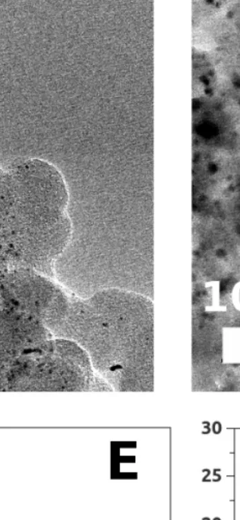
212 membrane, commercial air cathode) being kept identical. The experimental details of the fuel cells can be found in the Appendix A.2 of this thesis. It was checked that the two anodic active layers were comparable, such as the Pt/C and the Pd/C nanoparticle size (nanoparticle mean diameter of 2.2 nm and 2.5 nm for Pt/C and Pd/C catalysts, respectively, calculated by measuring at least 300 nanoparticles from the TEM imaging) or the metal loading (ca. 0.5 mg of Pt or Pd per cm2 of carbon cloth, confirmed by ICP-AES analysis).
The half-cell characterizations presented above in this chapter enabled to study the anodic part of the fuel cell isolated from the other fuel cell variables. Therefore, in order to draw a pertinent comparison between the half-cell and the fuel cell characterizations, one should make sure that the fuel cell is not mostly limited by the cathodic reaction and the ohmic drop, otherwise the study of anodic catalyst material and/or anodic fuel would be pointless. The cathodic reaction is not the main limiting step in the overall fuel cell performances of our study, thanks to the high Pt loading at the cathode (2 mgPt.cm−2) as well as high pure oxygen cathodic
flow (300 mL.min−1).
Fig.1.2 shows voltammograms obtained at a scan rate of 25 mV.s−1 for fuel cells operated at
25°C, using Pt/C or Pd/C anodic catalysts fed with 7.5 mL.min−1 of 5 M NaOH + either 1 M
NaBH4 or 1 M NH3BH3. The fuel cell using Pd/C and ammonia borane as anodic catalyst and
anodic fuel, respectively, displays the highest open cell voltage (OCV) with a value of 1.05 V, while the fuel cell using the same ammonia borane as anodic fuel but Pt/C as anodic catalyst dis-plays the highest performances in terms of maximum power density (181 mW.cm−2). The main
features of these fuel cell characterizations (OCV and maximum power density) are reported in Table 1.1 along with the benchmarks obtained from half-cell measurements at room temperature. The main features of the half-cell characterizations reported in Table 1.1. are in agreement with the performances of the fuel cells. Indeed, as the Pd RDE displays the lowest OCP when in contact with ammonia borane, the Pd/C anodic catalyst fed with ammonia borane (Pd/C-NH3BH3) shows the highest OCV in fuel cell configuration (ca. 100 mV higher than the
other fuel cells) and so the best performances at low current densities (below ca. 200 mA.cm−2).
At higher current densities, this configuration is outperformed by the Pt/C anode fed with ammonia borane, which shows the highest peak in power density among all other fuel cells. The Pd catalyst with sodium borohydride displays the worst performances in both half-cell and in fuel cell configurations. However in this case, the correlation between the half-cell OCP and the fuel cell OCV is not straightforward. This can be explained by the sluggish oxidation kinetics of BH−
4 on the Pd RDE, which induces uncertainties on the OCP measurement. Indeed, the
double layer capacitive current will, for example, lead to a non-negligible positive shift of the OCP value (when this potential value is taken as the intersection of the positive-going curve of
Figure 1.2: Voltammograms at 25°C in fuel cell configuration using homemade Pt/C or Pd/C on carbon cloth as anodes (0.5 mg of Pt or Pd per cm2) fed by 7.5 mL.min−1 of 5 M NaOH
+ either 1 M NaBH4 or 1 M NH3BH3, commercial Pt/C on Toray paper as cathode (2 mg of
Pt per cm2) fed by 300 mL.min−1 of pure oxygen (atmospheric pressure) and Nafion® 212 as a
cationic membrane. Scan rate of 25 mV.s−1.
the voltammogram with the j = 0 x-axis).
Another possible explanation for the drop in performances at higher currents for Pd/C-NH3BH3 (besides the relatively low number of electrons involved in the low-potential ABOR on
Pd observed in Fig.1.1B) is the gas generated from the heterogeneous hydrolysis of NaBH4 and
NH3BH3 on Pt and Pd. Indeed, during the fuel cell operation, it was visually observed that
NH3BH3 generated more gas (possibly H2, NH3 or N2) than NaBH4 (H2) both with Pt/C and
Pd/C. This gas generation also likely accounts for the noisier fuel cell voltammograms using NH3BH3 in Fig.1.2 and could explain the better performances of Pt/C-NaBH4 compared to
Pd/C-NH3BH3, which could not be expected from the half-cell results. Indeed, the latter were
performed under hydrodynamic regime (in RDE) for smooth electrodes, thereby favoring the fast removal of the gas bubbles that could render to the catalyst surface inaccessible. This is obviously less likely for active sites spread within a volumic porous layer in the fuel cell configuration, in which gas evolution leads to a deterioration of the performances of the fuel cell [55, 56, 57]. The molar ratio between sodium borohydride or ammonia borane and sodium hydroxyde also differs between the half-cell configuration (1:100, respectively) and the fuel cell configuration (1:5, respectively). This difference tends to minimize the hydrolysis issue encountered in half-cell configuration, compared to the fuel cell configuration.
From the voltammograms in fuel cell configuration of Fig.1.2, ammonia borane is more efficient than sodium borohydride as an anodic fuel at 25°C. It leads the highest OCV value and maximum power density when Pd/C and Pt/C are used as anodic catalysts, respectively. This conclusion agrees with the half-cell results, and highlights the relatively good predictive power of the half-cell characterization for comparing the anodic catalyst material as well as the anodic
Table 1.1: Performances of the fuel cells operating at 25°C. Benchmarks of the half-cell characterizations.
Half-cell configuration
Working electrode Pt Pt Pd Pd Electrolyte NaBH4 NH3BH3 NaBH4 NH3BH3
OCP vs. RHE (V) -0.024 -0.052 -0.027 -0.274 Potential vs. RHE at 1 mA.cm−2 (V) -0.009 -0.046 0.084 -0.261
Potential vs. RHE at 10 mA.cm−2 (V) 0.122 0.045 0.280 -0.170
Potential vs. RHE at 20 mA.cm−2 (V) 0.212 0.167 0.342 0.460
Potential vs. RHE at 30 mA.cm−2 (V) 0.273 0.669 0.654 0.641
Fuel cell configuration
Anodic catalyst Pt/C Pt/C Pd/C Pd/C Anodic fuel NaBH4 NH3BH3 NaBH4 NH3BH3
OCV (V) 0.941 0.947 0.991 1.050 Maximum power density (mW.cm−2) 158 181 81 154
fuel for an alkaline fuel cell application (being kept in mind the bias coming from the generation of H2 mentioned above). The link between the half-cell and the fuel cell can in some cases not
be straightforward, as the many variables influencing the fuel cell experiments may change the conclusions of the half-cell results. For example, the fuel cross-over occurring in the fuel cell may lead to low OCV values unexpected by the OCP measurements in half-cell configuration. The hydrogen produced during the hydrolysis reactions also likely influences the OCV in the fuel cell experiments; especially in the case of Pd in contact with ammonia borane in which the presence of H2 can drag the anode open circuit potential to values closer to the H2/H2O equilibrium
potential, and thus lead to lower OCV values than expected from the half-cell results. Moreover, the cross-over issue in fuel cell configuration has certainly a stronger impact for the DABFC, as NH+
4 possibly generated during the anodic reaction can easily cross the Nafion® membrane
and reduce the cathodic potential. In spite of these uncertainties, characterization in half-cell configuration appears to be the most pertinent comparison means of anodic catalyst materials and/or anodic fuel performances for alkaline fuel cell application.
1.3 Influence of the operating temperature on the fuel
cell characterization
Fuel cell characterizations were performed at various operating temperatures; the voltammo-grams (at a scan rate of 25 mV.s−1) are shown in Fig.1.3 for Pt/C and Pd/C anodic catalysts.
The performances of the fuel cells (OCV and maximum power density) are reported in Table 1.2. The highest peak in power density, shown in Fig.1.3A, is reached for the fuel cell using Pt/C as anodic catalyst and sodium borohydride as anodic fuel, at 60°C (Pt/C-NaBH4-60°C)
Figure 1.3: Voltammograms in fuel cell configuration operating at various temperature, using homemade Pt/C (A) and Pd/C (B) on carbon cloth as anodic catalysts (0.5 mg of Pt or Pd per cm2) fed by 7.5 mL.min−1 of 5 M NaOH + either 1 M NaBH4 or 1 M NH3BH3, commercial
Pt/C on Toray paper as cathodic catalyst (2 mg of Pt per cm2) fed by 300 mL.min−1 of pure
oxygen (atmospheric pressure) and Nafion® 212 as a cationic membrane. Scan rate of 25 mV.s−1.
Please note that our fuel cell characterizations were performed using voltammetry (25 mV.s−1), while most of DBFC characterizations in the literature are performed by plotting a
polarization curve; however, the rate at which it was obtained, i.e. the time spent at each potential/current prior acquisition of the data point, is rarely specified. A voltammetry likely leads to higher values of power density than a characterization using the polarization technique, owing to the capacitive contribution and the decreased poisoning effects that were reported to hinder the BOR catalysis [58, 59, 60]. The author points out that the voltammetry technique
Table 1.2: Performances of the fuel cells operating at various temperature. The fuel cell operating conditions are denoted as follows: ’anodic catalyst-anodic fuel-operating temperature’. All other operating conditions are identical.
Fuel cell operating conditions OCV (V) Maximum power density (mW.cm−2)
at [Current density (mA.cm−2)]
Pt/C-NH3BH3-25°C 0.947 181 [400] Pt/C-NH3BH3-60°C 0.941 300 [690] Pt/C-NH3BH3-80°C 0.929 305 [770] Pt/C-NaBH4-25°C 0.941 158 [325] Pt/C-NaBH4-60°C 0.942 420 [890] Pt/C-NaBH4-80°C 0.935 415 [870] Pd/C-NH3BH3-25°C 1.050 154 [300] Pd/C-NH3BH3-60°C 1.019 240 [520] Pd/C-NH3BH3-80°C 0.975 190 [340] Pd/C-NaBH4-25°C 0.991 81 [180] Pd/C-NaBH4-60°C 0.985 212 [420] Pd/C-NaBH4-80°C 0.985 310 [640]
was chosen here in order to measure reliable and reproducible cell potential vs. current density curves for characterizing the fuel cell and to study the influence of the anodic catalyst material and fuel. Indeed, plotting a polarization curve takes a long time (during which hydrogen can evolve and accumulate) and requires a large amount of fuel, so that it can prove difficult to obtain reproducible polarization curves with the same fuel cell assembly [61]. On the contrary, the voltammograms presented in this work were stable upon voltage cycling (except for the noise in the voltammograms due to gaseous hydrogen generation). As stated before, the primary aim of this work is not the achievement of the best possible performances in fully optimized systems, but rather the study of different types of anodes using similar fuel cells configuration and characterization method. Cyclic voltammetry is a suitable characterization method for this purpose. One of the disadvantages of the voltammetry technique though, is that it does not allow measuring the gas generation within the fuel cell during operation, unless an on-line gas flow meter is installed [46, 62].
The improvement of the performances when increasing the operating temperature are much less visible when ammonia borane is used as an anodic fuel compared to sodium borohydride. Indeed, while ammonia borane is more efficient than sodium borohydride at 25°C (highest OCV and highest maximum power density using Pd/C and Pt/C as anodic catalysts, respectively), the ammonia borane fuel cells are outperformed by the fuel cell using Pt/C fed with sodium borohydride operating at 60°C and 80°C in terms of power density. The advantage of ammonia borane, which displays the highest OCV at 25°C when Pd/C is used as the anodic catalyst, also disappears when the operating temperature increases. Indeed, the OCV sharply decreases with the increase of the operating temperature for the fuel cell using Pd/C as anodic catalyst and ammonia borane as anodic fuel (1.050 V, 1.019 V and 0.975 V for respectively 25°C, 60°C and 80°C), while the OCV remains relatively constant with the increase of the operating temperature in the case of sodium borohydride. It is likely that the increase of the hydrolysis rate of NH3BH3
on Pd/C and Pt/C versus the temperature is responsible for this phenomenon. Indeed, a harsh gas generation inside the fuel cell was observed at 60°C and 80°C when ammonia borane was used as the anodic fuel, which accounts for the noisiness of the fuel cell voltammograms in these cases (Fig.1.3). The cross-over of NH+
temperature and likely contributes to the loss of performance in fuel cell configuration at higher temperature when NH3BH3 is used as the anodic fuel, compared to NaBH4.
Increasing the operating temperature usually increases the fuel cell performances, by en-hancing the reactions and mass-transfer kinetics, and by decreasing the ohmic losses. However in our case, although the results show that raising the operating temperature from 25°C to 60°C indeed increases all the fuel cell performances, the trend is not true anymore from 60°C to 80°C, in which case the fuel cell performances remain equal or even decrease (Fig.1.3). This behavior is likely explained by the increase of the sodium borohydride and ammonia borane hydrolysis rate, that opposes the usual beneficial effects of an increased operating temperature on the performances of the fuel cells. As a result, the optimum temperature is found around 60°C in this setup. An exception to this general observation is for the fuel cell using Pd/C as an anodic catalyst and sodium borohydride as anodic fuel, for which the performances still increase at 80°C. This behavior can be explained by the very sluggish BH−
4 oxidation reaction
kinetics on Pd, as observed at 25°C in the half-cell characterizations (Fig.1.1B, Table 1.1); the enhancement of the oxidation reaction kinetics upon temperature increase still compensates for the combined increase of the hydrolysis rate. In all cases, the voltammograms of Fig.1.3 do no present any well-defined limiting current densities, which rules out any consequent mass-transfer limitation in the fuel cell setup in the present operating conditions.
Potentiostatic electrochemical impedance spectroscopy (PEIS) measurements were performed around the OCV in fuel cell configuration at various operating temperatures using sodium borohydride as anodic fuel; the Nyquist plots are presented in Fig.1.4A. The value of the polarization resistance (real part of impedance at the lowest frequency of the sinusoidal potential input signal in the Nyquist plot of Fig.1.4A) is related to the reaction kinetics and mass-transfer limitations in the fuel cells. The fuel cell operating at 25°C and using Pd/C as anode catalyst (Pd/C-NaBH4-25°C) displays the highest polarization resistance. This is in agreement with
the sluggish BH−
4 oxidation reaction kinetics on Pd observed in the half-cell characterizations
(Fig.1.1B). Raising the operating temperature from 25°C to 60°C decreases all the polarization resistances values, as the reactions and mass-transfer kinetics improve. However, the polarization resistance of Pt/C-NaBH4-80°C is higher than for Pt/C-NaBH4-60°C (Fig.1.4A). As mentioned
previously in this section, this result is attributed to the influence of the BH−
4 hydrolysis
reaction on Pt, enhanced by increased operating temperature. In agreement with the fuel cell voltammograms of Fig.1.3A, the optimal operating temperature for the fuel cell using sodium borohydride and Pt/C as respectively anodic fuel and catalyst is around 60°C. The experimental Nyquist plots of Fig.1.4A were examined using Kramers-Kronig (K-K) transform (performed using the EC-Lab® software). The only parts of the Nyquist plots that did not satisfy the
K-K transform were the ’tails’ formed by the points obtained for the lowest frequencies of the potential input signal in the Nyquist plots of Pt/C and Pd/C at 25°C (Fig.1.4A), suggesting a time-dependent behavior. One possible explanation for this dependence in time would be the blocking of the catalysts (even at OCV) when in contact with sodium borohydride [59].
The ohmic resistance of the cell corresponds to the real part of the impedance for the points measured with the highest frequency of the sinusoidal potential input signal in the Nyquist plot (Fig.1.4B). As expected, the ohmic resistance values of the fuel cell assemblies decrease for increasing operating temperature. This decrease of the ohmic resistance contributes to the general improvement in fuel cell performances, along with the enhanced reaction kinetics, when increasing the operating temperature. It is also worth noting that the ’Pt/C’ and ’Pd/C fuel cell assemblies’ do not show exactly the same values of ohmic resistance at the same operating temperature (Fig.1.4B). This difference in ohmic resistance can be explained by differences in
Figure 1.4: A: Nyquist plot of potentiostatic electrochemical impedance spectroscopy performed on DBFC operating at various temperature, using homemade Pd/C or Pt/C on carbon cloth as anodic catalysts (0.5 mg of Pt or Pd per cm2) fed by 7.5 mL.min−1 of 5 M NaOH + 1 M
NaBH4, commercial Pt/C on Toray paper as cathodic catalyst (2 mg of Pt per cm2) fed by
300 mL.min−1 of pure oxygen and Nafion® 212 as a cationic membrane. Potential oscillations
around the OCV with a peak to peak amplitude of 20 mV, frequency from 62 kHz to 0.1 Hz. 6 points per frequency decade. B: Zoom of graph A in the high frequency region.
the set-up of these two assemblies, which can lead to slight variation of the contact resistance. However, this difference in ohmic resistance between the two fuel cell assemblies at the same operating temperature has a negligible influence on the fuel cell voltammograms of Fig.1.3. For example, in the case of Pt/C-NaBH4-25°C and Pd/C-NaBH4-25°C, the difference in ohmic
resistance is ca. 0.03 Ω.cm2 (Fig.1.4B). This induces a difference in ohmic drop of ca. 11 mV at
a current density of 380 mA.cm−2 (current density for which the cell voltage of Pd/C-NaBH4-25
reaches 0 V in the fuel cell characterization of Fig.1.2), while the difference in cell voltage at 380 mA.cm−2 between Pt/C-NaBH4-25°C and Pd/C-NaBH4-25°C is ca. 390 mV in Fig.1.2. Thus,
the fuel cell voltammograms of Fig.1.2 and Fig.1.3 were not corrected for the ohmic drop.
1.4 Influence of the anode morphology on the fuel cell
characterization
In the previous fuel cell characterizations presented in this study using Pt/C and sodium borohydride as, respectively, anodic catalyst and fuel, the Pt/C + Nafion® ink was pasted on
the carbon cloth (as further described in the dedicated Appendix A.2 of this thesis). In order to study the influence of the anodic active layer morphology on the fuel cell behavior, another configuration was used where the anodic Pt/C layer is coated by spray on one side of the Nafion®


![Figure 10: ’Medis 24-7 Power Pack’ DBFC charging a smartphone. Reproduced from the website of CNET [47]](https://thumb-eu.123doks.com/thumbv2/123doknet/6029463.150823/20.917.208.711.47.381/figure-medis-power-pack-charging-smartphone-reproduced-website.webp)