A Multi-Agent System to Regulate Bimodal
Urban Traffic
Neïla Bhouri1, Flavien Balbo2 and Suzanne Pinson2
1INRETS/GRETIA, "Le Descartes 2" 2 rue de la Butte Verte, 93166 Noisy Le Grand Cedex.
e-mail: [email protected] 2
University Paris-Dauphine - LAMSADE, Place du Marechal de Lattre de Tassigny F-75775 Paris 16 Cedex, France.
e-mail: [email protected], [email protected]
Abstract: This paper proposes a new strategy for urban bimodal traffic regulation based on a multi-agent model. We call bimodal traffic a traffic which takes into account private vehicles and public vehicles such as buses. The objective of this strategy is to improve global traffic and reduce the time spent by buses in traffic jams so that buses cope with their schedule. Reducing bus delays is done by studying time length of traffic lights, giving priority to buses, more precisely to buses running late. Bus priority is granted by reserving a green stage for buses as soon as they enter the given route. Regulation is obtained thanks to communication, collaboration and negotiation between the agents of the system. The implementation has been done using the JADE platform. We have tested our strategy on a small network of four intersections. The first results of the simulation are given. They show that our MAS control strategy improves both bus traffic and private vehicle traffic and decrease bus delays compared to a classical strategy called fixed-line control.
Key words: multi-agents, negotiation, urban traffic control, public transport priority, traffic light control, buses interval regulation, JADE platform.
1
INTRODUCTION
Several cities used regulation systems at junctions that grant priority to vehicles, the aim of which is to improve the route times of public surface transport (bus, tramways, shuttles, etc.), which are referred to as systems equipped with bus priority. The aim of these strategies is to increase the average speed needed to cross the junction for all vehicles as well as public transport vehicles.
The use of these systems is efficient when traffic is light or when used to benefit a single congested bus route. Studies show that the use of bus priority can produce a time saving of between 20% and 40% on the global bus journey [1]. However,
reducing the time of the bus journey, although very important for operating a route, is not the primary factor considered by public transport operators whose obligation is to provide a service to passengers.
This work concentrates on conditions of very heavy circulation; traffic is dense and the frequency of passage on bus routes is high. In addition, we are assuming that several bus routes are using the network; we are therefore concerned with regulating global traffic, to favor the passage of buses and to supervise the regularity of intervals at bus stops between vehicles along the same bus route.
Application of classic control theories to regulate the bi-mode traffic (public transport and private vehicles) is confronted to the modeling problem. It is not well adapted to follow a micro regulation approach, because microscopic modeling is time-consuming, and it is therefore not realist to build real time control strategies for wide urban networks. Private vehicles traffic can be considered as a continuous flow and represented by a macroscopic model. However it is difficult to consider public transport traffic as a continuous flow. Indeed, even when there are a high number of public transport vehicles on a network link, these vehicles often come from different public transport routes and cannot be considered as a same traffic flow.
The difficulty is to take into account within a same model a micro-regulation and a macro regulation point of views. Multi-Agent modeling can be a suitable answer to this scale problem.
The following section of this article presents notions of the traffic regulation domain including bus and vehicle traffic network regulation systems. The third section focuses on traffic regulation systems and describes our model: the network model and the identification of the agents with a detailed description of agents, their attributes, their objectives, as well as communication and collaboration protocols. The forth section provides details of the network and the first results of the simulation tests carried on. Finally, we conclude in the fifth section.
2
Urban Traffic Regulation: notion of the domain
In order to automate the transportation activity, the theoretical bus supply is computed. It gives the transportation plan which represents the optimum supply in a theoretical context. It may become obsolete as the urban traffic conditions evolve. Regulators (the staff in charge of monitoring the bus networks) have to ensure the success of the transportation plan, in the sense of adapting theoretical supply to satisfy the passenger demand according to the urban traffic disturbances. Two kinds of systems were developed to regulate bus traffic: at a microscopic level we find Transportation Regulation Support Systems (TRSS) and at a macroscopic level, we find junction traffic regulation systems and global traffic regulation systems.
2.1 Transportation Regulation Support Systems
Regulators use Automatic Vehicle Monitoring (AVM) systems in order to collect and display data at a microscopic level, taking into account each bus behavior (bus delays and advances). In [2] we have proposed to complete this system with a Decision Support System, in order to analyze the data so as to give a dynamic and contextual assessment of bus disturbances in real-time, as well as action planning and decision-making aid concerning delayed buses. The result is what is called a Transportation Regulation Support System (TRSS). We have developed a TRSS prototype called SATIR (Système Automatique de Traitement des Incidents en Réseau - Automatic System for Network Incident Processing) that was tested on the Brussels transportation network (STIB). SATIR is based on a multi-agent paradigm, where buses and stops are represented by interacting agents. This system opens perspectives regarding the development of new functionalities to improve the management of a bus network.
In [3], we have proposed a specific regulation procedure based on Monte-Carlo for the logic of regularity. A logic of regularity is one of the three logical principles of public transport regulation: i.e. when traffic is heavy or the frequency of passage along the route is high, the trips are carried out with the logic of regularity. In this kind of systems as well as in the other two kinds, the issue is not to decrease the difference between the theoretical time and real time, but to keep intervals between vehicles.
TRSS systems follow a micro-regulation based approach i.e. modeling the behavior of each bus. One of the weaknesses of these systems is that the private vehicle traffic flow is hardly taken into account. If it is taken into account, this is only as an external parameter that modify the route times of the buses. Another weakness is that traffic light management, which is one of the key factors of traffic jam and bus delays, is not included in the TRSS systems.
To tackle these limitations, global traffic regulation systems model both public vehicles i.e. buses and private vehicles as well as traffic light management.
2.2 Global traffic regulation systems
The problem of global traffic regulation that favors buses has been studied by [4] and [5]. However, in this research, the regulation of intervals was only indirectly taken into account. In these systems the problematic was to reduce the time spent in traffic jams so that buses cope with their bus schedule. [6] have studied the problem of global traffic regulation with, in addition, the regulation of intervals between buses. The work carried out described the dynamic of the system in a macroscopic way for general traffic, and in a microscopic way for buses. A multi-objective optimization had been applied to the system by using the method of Particle Swarm Optimization (PSO). The complexity of the model suggests that we can obtain better results with a Multi-Agent System (MAS) modeling. Our research stems from these remarks and aims to test this hypothesis.
We can notice that multi-agent systems are increasingly present in the field of traffic regulation. As an example, the regulation systems presented in [7], [8] and [9] tackled the issue of how to control traffic lights at junctions in order to improve traffic. The problem of traffic lights coordination on the thoroughfares of the route network has been solved in [10], [11], [12] and [13]. However, we are not aware of any application for the regulation of bi-modal traffic, which is the object of our research.
3
Network modeling
In this section, we first define our graph model of the bus routes. Then we propose an agentification of the system with a detailed description of the agents, their attributes, their objectives, as well as communication and collaboration protocols
3.1 Network urban modeling
The urban network is modeled by an oriented graph G= (I, A). The nodes {I} represent the junctions (or intersections) and the arcs {A} represent the lanes that connect the junctions. Two intersections can be connected by one or several arcs depending on the number of lanes on the thoroughfare.
An arc corresponds to a lane. It is characterized by a set of static and dynamic information. We focus on the list of successive arcs ai on which the vehicles can travel, its length Li (in meters), its capacity Ci (in private car unit, PCU), its saturation output Di, which is the maximum output of exits from the given arc (in PCU/second), the number Ni (in PCU) of vehicles on the arc, and finally, the state of the traffic lights at the extremity of the arc: green or red. If the light is green then the vehicles present on the arc can depart.
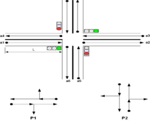
Fig. 1. Example of a junction with 4 arcs and two stages P1 and P2
Junction: a junction is specified by the set of the arcs that enter it {E} and the set
Pn}. Each of the stages specifies the list of arcs for which the green light is awarded if the stage is active.
Figure 1 illustrates an example of a two-stage junction P={P1, P2}. P1 allows for the clearing of the arcs a1 and a3, because the entry flow a1 and a3 can leave the junction at the same green light period. Similarly, P2 clears arcs a5 and a8. The entries and exits of the junction are respectively E={a1, a3, a5, a8} and S={a2, a4, a7, a6}.
The network is used by a number of bus routes. Each route comprises the number of buses of the same origin and in the same direction, and which services a number of predefined commercial bus stops at regular time intervals. The time spent by a bus at a commercial stop will be equal to the pre-set time for passengers to mount, plus additional time to regulate the interval, if required.
3.2 Identification of agents
In order to identify agents and design the MAS we represent an abstraction of the real system; for every entity of the real world is associated an entity (agent) in the virtual world. These entities interact among themselves and form a Multi-Agent System (MAS). Homogenous agents are called “agent-type” or “agent-class”. The developed MAS is made up of the following agent-types:
Junction Agent (JA): is the key agent of our architecture. It is in charge of
controlling a junction with traffic lights, and of developing a traffic signal plan. The junction agent modifies the planning of the lights according to data sent by approaching buses.
Stage Agent (SA): the traffic signal plan is elaborated thanks to the collaboration
of the junction and stage agents. Each stage agent is expected to determine the optimal green light split to clear the waiting vehicles on the arcs concerned by the stage. Thus, whatever the complexity of the junction is (and its physical configuration), it is managed by a set of stage agents interacting with the junction agent in order to develop a plan of actions for the traffic lights.
Bus Agent (BA): represents a bus in the real world. It circulates from one arc to
another, halts at commercial stops, halts at red lights and obeys the instructions of the route agent. The objective of each bus agent is to minimize the time spent at traffic lights (i.e. to minimize journey times).
Bus Route Agent (BRA): the bus agent (BA) only provides a local view of their
environment and, in particular, only the journey covered by the BA. Thus, local optimization carried out by bus agents can have a negative impact on the route, notably on its regularity (i.e. the formation of bus queues). To tackle this problem, we propose an agent who has a global view of the route agents, and who can control and modify their behavior in order to guarantee an efficient and regular service.
3.3 Description of agents
This section provides a description of the internal architecture of the agents.
3.3.1 Bus Agent (BA)
In order to minimize the time spent at traffic lights the bus agent interacts with junction agents and its hierarchical superior agent (bus route agent). All the buses have to provide a regular service and avoid bus queues, in other words, the frequency of buses passing commercial stops must remain stable. To achieve this latter objective, the bus agent can receive orders from the route agent (for example, stay at the stop for t seconds, if the bus is ahead with respect to the position of the preceding bus).
The bus agent is composed of a data module, which represents its internal state, and a communication module, which enables exchange with other system agents.
Behavior of a bus agent
Let t0 be the entering time of the bus agent which behaves in the following way: - on entering arc i, the bus agent retrieves information from the arc (the number of vehicles that precede it, the length, capacity, and exit output of the arc). By using this data, the bus agent calculates a time-space reservation, which is transmitted to the junction agent in order to prevent an eventual stop at the red light at the following junction. The junction agent then attempts to satisfy the demand (see junction agent below);
- when approaching a stop, the bus agent informs the associated route agent. The route agent then calculates the duration of the regulation interval and its level of priority and sends it to the bus. The bus must wait during the passenger loading time, as well as the potential regulation time, before leaving the stop.
Calculation of a green light reservation
The reservation of a time-space for the green light is specified by the interval of time during which the green light is granted to the actual arc so that the bus can pass without stopping at the next junction.
Let R be the reservation interval:
R = [tb, te]
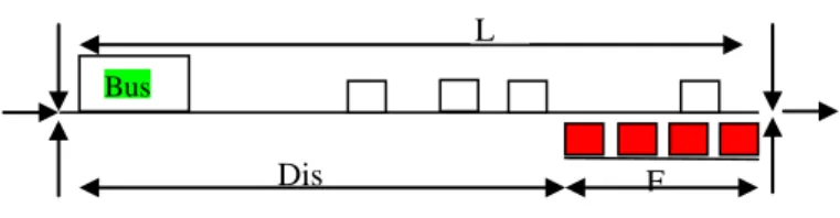
with tb and te be the beginning and end times of the reservation interval respectively. The calculation of these times is carried out as follows: the bus enters the arc and finds Nv vehicles ahead of it, the vehicles move to the traffic lights lane to wait for the green light thus forming a queue of length F (see Figure 2). In order to continue along its route, the queue of vehicles has to be dispersed before it arrives. The green light should thus be granted at the arc at the instant:
tb = to + T – TF
with T be the time necessary for the bus to cover the distance Dis separating it from the queue, and TF be the time necessary to disperse the queue F.
Fig. 2. Reservation of green light duration by a bus
This reservation interval R = [tb, te] together with other information (number of bus, its priority, actual arc of the bus, the next arc to be travelled by the bus) are sent to the junction agent (at the next junction) who attempts to modify the plan for the lights to satisfy the reservation.
3.3.2 Junction agent (JA)
The JA is the key agent of our architecture. The JA supervises the group of stage agents (SA), who collaborate together to establish a plan for traffic lights, which will, on the one hand, maximize the capacity of the junction and, on the other hand, attempt to satisfy, as far as possible, the reservation interval of the bus. The JA agent is characterized by static and dynamic data.
Static data
The static data represents the constraints which characterized the junction agent. It is defined as follows:
- The set of possible values of the cycle: the length of the cycle (in seconds) should not exceed a certain value. The optimal cycle computed by the strategy may include fractions of seconds and hence cannot be implemented, that’s why we impose that the cycle takes one of the following values: cycle Є {40, 60, 80, 100, 120}. For each cycle, there is an interval of lost time i.e. the period of orange or all red. The all red light is a period during which all the arcs from the same junction have a red light in order to clear the centre of the junction and thus prevent accidents. This fixed period, in conformity with the architecture of the junction, does not depend on the length of the cycle, with the result that the shorter the cycle the greater the loss of time and capacity of the junction.
- The set of stages of the junction: P = {P1, P2, ..., Pm}. The set of stages represents the configuration of the junction (the permitted movements and turns). Determining the stages is a task executed offline by the traffic experts.
Dynamic data
They are two types of dynamic data:
- The traffic signal plan: specifies the order of the stages as well as duration of each stage. Between two successive stages a two second period of all red is imposed.
- The list of received reservation data: each reservation is specified as follows: R = (Pi, tb, te, Priority), where Pi is the stage that will allow the passage of the given bus, tb the time when the bus expects to arrive at the traffic light, te, the time when the rear of the bus leaves the arc, and finally ‘Priority’ is the level of bus priority defined by the route agent.
Dis F
Bus
Behavior of the junction agent
At the end of each cycle, the JA triggers the process of calculating the traffic signal plan for the given cycle. This plan determines the duration of the green light and the ranking of each stage.
When the JA receives a reservation, it records it in the database. A reservation R=(Pi, tb, te, Priority) is not taken into account when it is received at t0 but at tb. The JA decides to accept or to refuse this request at time tb.
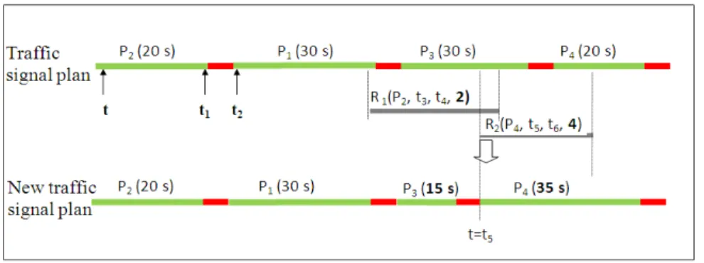
The behavior of the JA is explained thanks to the following example (see Figure 3) in which the junction has a plan with four stages and two antagonistic bus routes.
In this example, t represents the actual time; at time t1 the junction receives the reservation R1 which requests the extension of stage P1 up to instant t4 for a bus with a priority equal to 2. At instant t2 the junction agent receives another reservation, R2 from a more prioritized bus (Priority = 4). The latter requests the stage P4. This is not possible to satisfy both requests (R1 and R2) because they involve two different stages at two time intervals that overlap each other. The junction agent delays as much as possible the modification of his plan. Thus, the reservation request R1 is studied at time t3 (start time) and not at time t1 (received time). This delay allows the junction agent to receive more reservations (it receives R2 at time t2 in the example) and thus avoid ineffective modifications. For example R1 is refused because reservation R2 is more prioritized.
Fig. 3: Example of a traffic signal plan and its modification
The modification of a traffic signal plan following a priority request by a bus is as follows:
- Extension of a stage (delay or advance), without exceeding the maximal duration of a stage.
Calculation of a traffic signal plan
The plan is calculated thanks to the collaboration of the junction agent and the stage agents. Each stage is associated with a stage agent which is in charge of calculating its duration.
The junction agent plays the role of a manager in supervising the stage agents, which act as participants.
1) The junction agent begins by forming a group of collaborators called collab_group including the list of stage agents that needs to be managed.
2) The junction agent initializes the variables: C = CycleMax (120 seconds), and t=0. Variable C controls the size of the calculated cycle.
3) The junction agent sends a message to the stage agents to inform them of the protocol initiated to calculate the traffic light plan.
4) The junction agent sends a message request to the agents of the collab_group asking them for the time necessary to clear all the vehicles from their stages, beginning at instant t.
5) Every agent, i, of the collab_group calculates its desired green light duration di and an index that measures the urgency Ii of the stage, and sends them to the manager. The section 3.3.3 presents the way parameters di and Ii are calculated.
6) When the manager receives all the responses, the sum of durations is calculated:
∑
==
m i id
d
1If d> C then the manager has to solve a conflict (i.e. the size of the cycle exceeds the maximum). Conflict is solved when d previously calculated becomes less or equal to C : d ≤ C.
7) The manager selects the most urgent stage, that is Pj, its duration is dj:
-then sends an accept message to the stage agent in charge of operating this stage;
-then withdraws the corresponding stage agent of collab_group; -then updates the variables C=C-dj, t=t+dj ;
8) finally moves to 4) as long as collab_group is not empty.
Conflict resolution
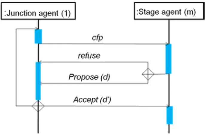
When the sum of green light durations requested by stage agents exceeds the size of the accepted value of the cycle, the manager must restore this sum to the maximal value of the cycle. To achieve this, the manager negotiates with the stage agents in order to reduce this sum at minimal cost. The manager sends a call to the stage agents. The agents can reduce their green light duration by a portion (Δt) in order to solve the problem. The cost of the offer is the number of buses penalized if the stage agent reduces its duration with Δt.
1) The manager initializes the cost c=1;
2) then sends a call_for_propose message (cfp) with a proposition and cost c to all the stage agents of the associated junction (see Figure 4);
3) the stage agents reply with a propose or refuse message (the modalities are explained in the section 3.3.3 on the behavior of the stage agents).
4) Once all the responses have been received by the manager, all the offers are added, such that:
5) If this sum restores the size of the cycle to the desired value then the conflict is solved. If not, the manager increments the cost c and sends a new proposition d’ (returns to step 2)
Fig. 4. Collaboration protocol in conflict resolution
3.3.3 Stage agent (SA)
A stage agent manages the set of moves compatible with bus entries onto a junction. The stage agent is in charge of calculating the optimal duration so as to clear the vehicles waiting on the corresponding arcs and collaborating with other agents in order to develop a traffic signal plan.
This agent has a collection of both static and dynamic data that represents its internal state:
Static data. It is as follows:
-The list of entry arcs: the set of arcs authorized to clear if the stage is active (or green).
-The original junction for each entry arc.
In a strictly formal manner, the list of arc entries is represented by E={(a1,c1), (a2,c2),..., (an, cn)} with ai is the entry arc i, ci is the original junction of the arc ai. This data structure enables the stage agent to retrieve traffic data at the entrance of the intersection at this stage, and to communicate with neighboring junction agents who can send traffic to the given junction.
Dynamic data. It is as follows:
- The state of the stage: active or inactive. ‘Active’ means that the traffic lights controlling the arcs concerned by this stage are green. The vehicles are therefore authorized to depart.
- The starting time of stage execution.
Behavior of the stage agent
The stage agent participates to the calculation process of the traffic signal plan, and is in charge of fixing the optimal duration of green light for the given stage.
1) When the stage agent is asked about the desired duration of green light by the junction agent, this duration di and an index Ii that measures the urgency of the stage are computed and transmitted to the junction agent.
2) If the stage agent receives confirmation from the junction agent, the stage agent stops the process.
3) If the stage agent receives a cfp with a cost c, it computes an offer and sends it to the junction agent.
Calculation of the desired duration of the green light
The optimal duration of green light is computed by the following formula:
{ }
i m iT
T
,..., 1max
==
with m is the number of entering arcs at this stage, and Ti the time necessary to clear arc i. Ti is given by:
i i i i i i i V * C L * N d N T = +
with for each arc i, Ni be the number of vehicles in private car unit (PCU), Di the saturation flow (PCU/second), Li the length (meter), Vi the average speed (meter/second) and Ci the capacity (PCU).
Urgency index of a stage
In order to award priority to a bus, the urgency index of a stage j is defined by the fact that the higher the index, the greater the urgency of the stage:
i i b m i w j
e
e
I
=
∑
+
=0 with:- wi = Ni / Ci ≤ 1, measures the degree of congestion of arc i, Ni and Ci are respectively the number of vehicles and the capacity of arc i
- bi : the number of buses present on arc i. - m: the number of arcs entering via stage j. - e: the Euler constant in our example.
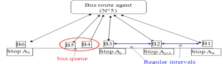
3.3.4 Bus route agent (BRA)
The role of the route agent is to supervise bus agents so as to prevent a local level regulation and the creation of bus queues. In other words, this agent can modify the behavior of bus agents in two different ways:
Directly: by keeping those buses, which are ahead in the plan compared to the
preceding ones, at the bus stop for a certain period of time.
This agent has a global view of the route it operates on, and can therefore detect bus queues and react to prevent queue formation. In the following example (Figure 6), the bus route agent (BRA N°5) detects the bus queue formed by bus agents B4 and B5 and can suppress it by slowing them.
Internal state of the route agent
The route agent encompasses the following data: - The set of arcs traveled by the bus on its route.
- The set of stops on the route: for each stop, its position, and the distance separating it from the next stop.
- The set of buses on the route.
- The frequency of buses introduced onto the route.
Fig. 5. Supervision of bus agents (BA) by the route agent (BRA).
For two consecutive stops Ai and Aj, the route agent maintains the journey time di,j of the last bus. This helps to follow the bus journey and to calculate whether the bus is ahead or late compared to the bus immediately preceding it.
Behavior of the route agent
When a bus agent moves to a stop, the time t taken to cover the distance Li,i-1 which separates the two stops Ai and Ai-1, is transmitted to the route agent. The route agent then compares t to the time (di,j) taken by the preceding bus and consequently decides whether the bus is ahead or late. The route agent computes the new priority of the bus agent as well as the length of time the bus should wait at the commercial stop if it is ahead [14].
4
Implementation of the prototype
In order to test our bimodal control strategy, we have developed a Multi-Agent System prototype on the JADE platform (Java Agent Development Framework).
4.1 JADE Environment
JADE offers Java middleware based on a peer-to-peer architecture with the overall aim to provide a runtime support for agents (JADE, 2009). To guarantee
inter-operability between agents, JADE is compliant with FIPA (Foundation for Intelligent Physical Agents) specifications.
The use of JADE simplifies the development of the multi-agent system. It offers a naming and yellow-page ser-vice, message transport and parsing service, and a library of FIPA interaction protocols ready for use. The agent platform provides a Graphical User Interface (GUI) for the remote management, monitoring and control of the status of agents.
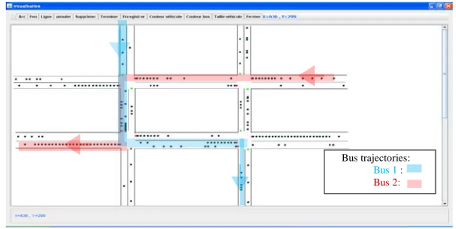
4.2 Urban network description for simulation tests
We have tested the strategy on a small network of four intersections. The configuration of the network is as follows:
- The junctions have between two and four stages.
- The distance between two adjacent junctions varies between 200 and 400 meters.
- Each section comprises one or two lanes (see Figure 6).
- The maximum exit output of the arcs is identical for each arc and equal to 0.5 vehicles/second.
- At each entry onto the network we have installed a source that generates vehicles at a frequency F∈ [4 s .. 10 s].
- Two buses enter the network (see Figure 6). For Bus 1, the frequency of the generated buses is 80 seconds and 180 seconds for Bus 2
Fig. 6. Architecture of the simulated network
4.3 Results
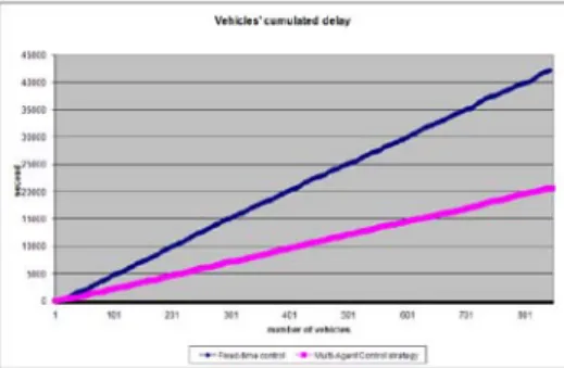
We have compared the developed SMA strategy to a fixed time strategy with 30 seconds for each stage. We have run the simulation with these two strategies and for half-hour simulation time. Figure 7 (resp. Figure 8) give results of the two strategies
Bus trajectories: Bus 1 : Bus 2:
for very heavy traffic conditions. Figures 7 and 8 show recorded delays for buses and for private vehicles respectively with the two control strategies.
These delays correspond to the sum of time lost by all buses (resp. vehicles) at stops on the traffic lights.
As shown on Figure 7 and Figure 8, the multi-agent control strategy improves both traffic of buses and traffic of private vehicles. As we can see, there is a decrease of 38% on lost time spent by buses on traffic light and about 51% for the private vehicles.
Fig. 7. Buses (public vehicles) cumulated delays.
Fig. 8. Private vehicles cumulated delays.
5
CONCLUSION
In this paper, we have developed a new traffic control strategy called bimodal control strategy based on a multi-agent system. The originality of this strategy is that it takes into account two transportation modes: public transportation i.e. buses and private vehicles. Thanks to new information and agent technologies, the entities representing the urban network can communicate among themselves and negotiate in order to solve traffic regulating problems. First, we have shown that classical methods of control systems of traffic regulation present several weaknesses: at a macroscopic level, they do not take into account mixed traffic and does not allow for the regulation of intervals between buses Furthermore computations at a microscopic level are
time-consuming specially for regulating large networks. In a second part, we have presented the multi-agent model that computes a plan for traffic lights based on the actual traffic situation and on those buses that deteriorate the intervals between the vehicles on the same route. In the third part, we have run a simulation prototype on the JADE platform. First results show that this new bimodal strategy improves conditions of global traffic and reduces bus delays. More work should be done: a more realistic network should be defined in the simulation run and more validation and more testing should be undertaken with the definition of several indicators.
REFERENCES
[1]. Stif, 2001. Guide technique des systèmes de priorité bus aux carrefours à feux. Rapport stif, Paris.
[2]. Balbo, F, Pinson, “Using intelligent agents for Transportation Regulation Support System design”, Transportation Research Part C: Emerging Technologies, Volume 18, Issue 1, February 2010, Pages 140-156 Information/Communication Technologies and Travel Behaviour; Agents in Traffic and Transportation.
[3]. Cazenave T., Balbo F., Pinson S. "Monte-Carlo Bus Regulation", 12th International IEEE Conference on Intelligent Transportation Systems, October 3-7, 2009, St. Louis, MO, USA, 6 pages.
[4]. Bhouri, N. et P. Lotito, 2005. An intermodal traffic control strategy for private vehicle and public trans-port. 10th Euro Working Group on Transportation, Poznan, Pologne.
[5]. Bhouri, N., 2009, Constrained Optimal Control strategy for multimodal urban traffic network. IFAC Workshop on Control Applications of Optimization (CAO'09), Finland, May.
[6]. Kachroudi, S. et N. Bhouri, 2009. A multimodal traffic responsive strategy using particle swarm optimi-zation. 12th IFAC Symposium (CTS’09). Redondo Beach, California, USA, September 2-4.
[7]. Bazzan A. L. C. 2008. “Opportunities for multiagent systems and multiagent reinforcement learning in traffic control”, Published online: 7 September 2008, Springer Science+Business Media, LLC 2008
[8]. Mizuno, K., Y. Fukui et S. Nishihara, 2008. Urban Traffic Signal Control Based on Distributed Constraint Satisfaction, Proceedings of the 41st International Conference on System Sciences. Hawaii.
[9]. Mailler R. et V. Lesser V, 2004. Solving distributed constraint optimization problems using coop-erative mediation”. In Third International Joint Conference on Autonomous Agents and Multiagent Systems, pages 438-445. IEEE Computer Society.
[10]. De Oliveira D, A.L. Bazzan and V. Lesser V, 2005. Using Cooperative Mediation to Coordinate Traffic Lights, AAMAS’05, July 2529, 2005, Utrecht, Netherlands.
[11]. Ferreira, E.D. , E. Subrahmanian et D. Manstetten, 2001. Intelligent agents in decentralized traffic control, IEEE Intelligent Transportation Systems Conference Proceedings - Oakland (CA), USA - August 25-29.
[12]. France, J. et A. Ghorbani,2003. A multiagent system for optimizing urban traffic. In Proceedings of the IEEE/WIC Inter. Conf. on IAT (pp. 411–414). Washington, DC: IEEE Computer Society. 2003.
[13]. Roozemond D. A., 2001. using intelligent agents for pro-active, real-time urban intersection con-trol”, European Journal for Operationel Research 131. pp 293-301.
[14] Bhouri, N., S. Haciane and F. Balbo, 2010. A Multi-Agent System to Regulate Urban Traffic: Private Vehicles and Public Transport. 13th IEEE–ITSC, Portugal, 19 -22 September.