HAL Id: pastel-00649350
https://pastel.archives-ouvertes.fr/pastel-00649350
Submitted on 29 Feb 2012
HAL is a multi-disciplinary open access
archive for the deposit and dissemination of
sci-entific research documents, whether they are
pub-lished or not. The documents may come from
teaching and research institutions in France or
abroad, or from public or private research centers.
L’archive ouverte pluridisciplinaire HAL, est
destinée au dépôt et à la diffusion de documents
scientifiques de niveau recherche, publiés ou non,
émanant des établissements d’enseignement et de
recherche français ou étrangers, des laboratoires
publics ou privés.
Autonomous Systems in the Internet
Juan Antonio Cordero
To cite this version:
Juan Antonio Cordero. Link-State Routing Optimization for Compound Autonomous Systems in
the Internet. Networking and Internet Architecture [cs.NI]. Ecole Polytechnique X, 2011. English.
�pastel-00649350�
Autonomous Systems in the Internet
A dissertation presented by
Juan Antonio Cordero
to
The Doctoral School of ´Ecole Polytechnique (EDX) in partial fulfillment of the requirements
for the degree of
Docteur de l’ ´Ecole Polytechnique in the subject of
Mathematics & Computer Science
´
Ecole Polytechnique France June 2011
Autonomes Hybrides sur Internet
Th`ese present´ee par
Juan Antonio Cordero
`a
l’´Ecole Doctorale de l’´Ecole Polytechnique (EDX)
pour obtenir le grade de
Docteur de l’ ´Ecole Polytechnique en
Math´ematiques et Informatique
´
Ecole Polytechnique France Juin 2011
Thesis defended on September 15th, 2011, before a Ph.D jury formed by: Th`ese soutenue le 15 septembre 2011, devant un jury form´e par:
• Philippe ROBERT, Ph.D, HDR, INRIA Paris–Rocquencourt / ´Ecole Polytechnique Examiner and president of the jury — Examinateur et pr´esident du jury
• Christophe GUETTIER, Ph.D, SAGEM D´efense et S´ecurit´e Examiner — Examinateur
• Thomas R. HENDERSON, Ph.D, The Boeing Company / University of Washington (UW) Examiner — Examinateur
• Mark TOWNSLEY, Cisco Inc. Examiner — Examinateur
• Mukul GOYAL, Ph.D, University of Wisconsin–Milwaukee (UWM) Reviewer — Rapporteur
• David SIMPLOT-RYL, Ph.D, HDR, INRIA Nord / Universit´e de Lille 1 Reviewer — Rapporteur
• Andr´e-Luc BEYLOT, Ph.D, HDR, ENSEEIHT / Universit´e de Toulouse Reviewer — Rapporteur
• Philippe JACQUET, Ph.D, HDR, INRIA Paris–Rocquencourt / ´Ecole Polytechnique Ph.D advisor — Directeur de th`ese
• Emmanuel BACCELLI, Ph.D, INRIA Paris–Rocquencourt Ph.D co-advisor — Co-encadrant
Awarded with mention Qualifi´ee avec mention
Philippe Jacquet & Emmanuel Baccelli Juan Antonio Cordero
Abstract
This manuscript addresses the coexistence of planned and spontaneous interconnected net-works in the Internet core. In this realm, the focus is on routing within a specific type of Autonomous System (AS) called compound AS, which contains both wireless ad hoc networks and wired fixed networks. The approach studied in this manuscript is to enhance existing Interior Gateway Proto-cols (IGPs), typically based on the link-state algorithm, in order to enable them to operate both in ad hoc networks and in wired networks.
The manuscript thus analyzes the use of link-state routing in ad hoc networks. Based on this analysis, different techniques are proposed and theoretically evaluated, aiming at optimizing the performance of link state routing in a compound AS.
The manuscript then investigates the impact of these techniques when applied to OSPF, one of the main IGPs used in the Internet. The performance of OSPF extensions on MANETs using the studied techniques are compared via simulations. Finally, OSPF operation over compound internetworks is evaluated via experiments on a testbed.
Philippe Jacquet & Emmanuel Baccelli Juan Antonio Cordero
R´
esum´
e
Ce manuscrit ´etudie la coexistence de r´eseaux fixes et de r´eseaux spontan´es dans le coeur d’Internet. Plus particuli`erement, on ´etudie le probl`eme du routage dans un certain type de syst`eme autonome (AS) appel´e AS hybrides, qui contiennent `a la fois des r´eseaux ad hoc sans fil et des r´eseaux filaires. L’approche propos´ee dans ce manuscrit est d’adapter des protocoles actuellement utilis´es dans les AS au coeur d’Internet, typiquement bas´es sur l’algorithme `a ´etat des liens, pour leur permettre d’op´erer dans les r´eseaux ad hoc (MANETs) comme dans les r´eseaux filaires.
Le manuscrit analyse donc l’utilisation du routage `a ´etat de liens dans les r´eseaux ad hoc. Diff´erentes techniques sont ensuite propos´ees et ´evalu´ees th´eoriquement, dans le but d’optimiser la performance des protocoles `a ´etat de liens dans les AS hybrides.
Le manuscrit ´etudie alors l’impact de ces techniques lorsqu’elles sont appliqu´ees `a OSPF, l’un des principaux protocoles actuellement utilis´es dans les AS. Les performances d’OSPF dans les MANETs utilisant les diff´erentes techniques ´etudi´ees sont ensuite analys´ees au moyen de simulations. Pour finir, le fonctionnement du protocole OSPF utilisant certaines des techniques ´etudi´ees est ´evalu´e au moyen d’exp´eriences sur un r´eseau test r´eel.
y una canci´on desesperada)
“— Ce qui embellit le d´esert, dit le petit prince, c’est qu’il cache un puits quelque part...” (Antoine de Saint-Exup´ery, Le petit prince)
“— How am I to get in?, asked Alice again, in a louder tone. — Are you to get in at all?, said the Footman. That’s the first question, you know. It was, no doubt: only Alice did not like to be told so.” (Lewis Carroll, Alice’s adventures in Wonderland)
A mi hermana, que aunque a´un no lo sepa, ya ha empezado a ganar el pulso con la ciencia que todo cient´ıfico debe dar antes o despu´es. Y a mi primo Luis Antonio, que es otro Cordero expatriado.
First of all, I want to thank the three professors and researchers from the HIPERCOM team that have guided my research during my stay in Paris: Philippe Jacquet, Emmanuel Baccelli and Thomas H. Clausen. Their scientific advise has been essential for the successful completion of this Ph.D. Without their support and their help, the work presented in this manuscript would have been less complete and way more painful to do.
I want to thank all those who accepted to review the manuscript, and in particular the members of the jury, reviewers and examiners, for accepting to examine my work. Their com-ments have been useful and constructive, and the manuscript has significantly profitted from their experience and feedback.
I would also like to thank my current and former colleagues in the HIPERCOM team and LIX for their friendship and the nice times shared in the lab; they made the office a very pleasant place to work. I greatly enjoyed working, but also discussing and having fun, with (in approximate order of appearance) Ulrich Herberg, Georgios Rodolakis, Song-Yean Cho, Nestor Mariyasagayam, Veronika Bauer, Matthias Philipp, Georg Wittenburg, Alberto Camacho, Axel Colin de Verdi`ere, Jiazi Zi and Ming-Chih Chien. The same goes to other colleagues from LIX, in particular Vivek Nigam and Carlos Olarte.
I want to thank the assistants that have worked in HIPERCOM during my stay in Paris for their kindness and help in any administrative matter. Without the support of Lydie Fontaine, Marie-Jeanne Gaffard, Cindy Vingadassamy and Val´erie Lecompte, I would have been lost too many times within the complex administrative procedures of French administration.
Outside Polytechnique, I want to mention the friends I have met at the Colegio de Espa˜na in Paris, mostly (but not only) Ph.D students as me. They reminded me that there was something else in life than research, and made smoother the last months of hard work before the defense.
Beyond the Pyren´ees, I am of course very grateful to my parents and my sister Elena. This work would simply not exist without them, their tireless encouragement and their patience, anytime, anywhere.
I thank also Cl`audia for her support in these years.
Introduction 1
Structure and Overview . . . 10
I
NETWORKING FUNDAMENTALS
13
1 Computer Networks 15 1.1 Outline . . . 161.2 Networking and Routing Concepts . . . 17
1.2.1 Networks and Links . . . 17
1.2.2 Graph and Hypergraph Representation . . . 20
1.3 Addresses, Direct and Indirect Communication . . . 22
1.4 Connecting Networks . . . 26
1.4.1 IP Addressing and IP Links . . . 27
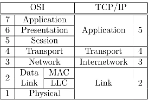
1.4.2 Network Reference Models . . . 31
1.4.3 Routing in the Internet . . . 34
1.5 Conclusion . . . 36
2 Wireless Computer Networking 39 2.1 Outline . . . 39
2.2 Wireless Communication . . . 40
2.2.1 Frequency of Wireless Signals . . . 40
2.2.2 Coverage and Interference in Wireless Interfaces . . . 41
2.2.3 Wireless Links . . . 44
2.2.4 Semibroadcast Properties of Wireless Communication . . . 46
2.3 Wireless Networks under the IP Model . . . 48
2.3.1 IEEE 802.11 . . . 50
2.4 Conclusion . . . 52
3 Communication in Ad hoc Networks and Compound ASes 55 3.1 Outline . . . 55
3.2 Ad hoc Networks and Compound ASes . . . 56
3.2.1 Ad hoc Networks and Applications . . . 56
3.2.2 Compound Autonomous Systems . . . 60
3.3 Nodes, Links and Addresses in Ad hoc Networks . . . 61
3.4 Single and Multi-Hop Communication . . . 63 xv
3.4.1 Neighbor Sensing . . . 64
3.4.2 Routing in Ad hoc Networks and Compound ASes . . . 65
3.5 Conclusion . . . 69
II
LINK-STATE ROUTING IN AD HOC NETWORKS
71
4 Elements of Link State Routing 73 4.1 Outline . . . 734.2 The Link State Database . . . 74
4.3 Topology Acquisition . . . 75
4.3.1 Flooding . . . 75
4.3.2 LSDB Synchronization . . . 77
4.4 Issues in Ad hoc Networks and Compound ASes . . . 78
4.4.1 General Bandwidth Constraints . . . 79
4.4.2 Flooding over Wireless Interfaces . . . 80
4.4.3 LSDB Synchronization in Compound ASes . . . 81
4.5 Conclusion . . . 83
5 Packet Jittering for Wireless Dissemination 85 5.1 Outline . . . 85
5.1.1 Terminology . . . 86
5.2 The Jitter Mechanism . . . 86
5.2.1 Common Input and Common Configuration . . . 87
5.2.2 Wireless Collisions and Jitter in Link-State Routing . . . 88
5.2.3 Forwarding Flooding Packets with Jitter . . . 89
5.3 Analytical Model . . . 91
5.3.1 Traffic Model and Assumptions . . . 93
5.3.2 Message and Packet Rates . . . 94
5.3.3 Statistical Description of Traffic to be Forwarded . . . 96
5.3.4 Time to Transmission for a Received Message . . . 103
5.3.5 Discussion of Results and Model Limitations . . . 115
5.4 Simulations . . . 117
5.5 Conclusion . . . 119
6 Overlays in Link State Routing 121 6.1 Outline . . . 121
6.2 LS Routing in terms of Overlays . . . 122
6.2.1 Topology Update Flooding . . . 123
6.2.2 Point-to-point Synchronization . . . 124
6.2.3 Topology Selection . . . 125
6.3 Full Network Overlay . . . 127
6.3.1 Full Network Topology Flooding . . . 127
6.3.2 Full Network Synchronization . . . 129
6.3.3 Overall Control Traffic . . . 130
7 The Synchronized Link Overlay Triangular – SLOT 133
7.1 Outline . . . 133
7.2 Definition, Related Overlays and Variations . . . 134
7.2.1 Gabriel Graphs and Relative Neighborhood Graphs . . . 135
7.2.2 The Synchronized Link Overlay and SLOT . . . 136
7.2.3 SLOT-U and SLOT-D . . . 138
7.3 Performance Analysis for 2-Dimensional Networks . . . 139
7.3.1 Overlay Density . . . 140
7.3.2 Link Stability . . . 142
7.3.3 Validation . . . 144
7.4 Performance Analysis for Other Dimensions . . . 147
7.4.1 1-Dimensional Networks . . . 147
7.4.2 3-Dimensional Networks . . . 150
7.5 Selection of Links depending on Distance . . . 151
7.6 Conclusion . . . 154
8 Multi-Point Relays – MPR 157 8.1 Outline . . . 157
8.2 Definitions and Heuristics . . . 158
8.2.1 Heuristics . . . 159
8.2.2 Implications . . . 160
8.3 MPR as a Flooding Overlay . . . 163
8.4 MPR as a Synchronized Overlay . . . 164
8.4.1 Asymptotic Connection and Density . . . 164
8.4.2 Link Change Rate and Persistency . . . 167
8.5 MPR as a Topology Selection Rule . . . 169
8.5.1 Path MPR . . . 170
8.5.2 Enhanced Path MPR . . . 172
8.6 Conclusion . . . 175
9 The Smart Peering Technique – SP 177 9.1 Outline . . . 177
9.2 Definition and Specification . . . 178
9.3 Asymptotic Properties . . . 179
9.4 Reaction to Mobility . . . 180
9.5 Conclusion . . . 184
III
APPLICATION TO OSPF
187
10 LS Routing Protocols within an AS 189 10.1 Outline . . . 19010.2 Open Shortest Path First – OSPF . . . 191
10.2.1 Architecture and Terminology . . . 191
10.2.2 Areas, Interfaces and Neighbors . . . 194
10.2.3 Packet and Message Types . . . 201
10.2.4 Single-Area OSPF for Non-Broadcast Networks . . . 203
10.3 Intermediate System to Intermediate System – IS-IS . . . 207
10.3.2 Interface Types . . . 210
10.4 Conclusion . . . 211
11 OSPF MANET Extensions 213 11.1 Outline . . . 213
11.2 IETF Standard Extensions . . . 214
11.2.1 Multipoint Relays – MPR-OSPF . . . 214
11.2.2 Overlapping Relays & Smart Peering – OR/SP . . . 217
11.2.3 MANET Designated Routers – OSPF-MDR . . . 220
11.3 Improved MPR-based Extensions . . . 221
11.3.1 Persistency Variations of MPR-OSPF . . . 222
11.3.2 SLOT over MPR-OSPF – SLOT-OSPF . . . 223
11.3.3 Multipoint Relays + Smart Peering – MPR+SP . . . 224
11.4 Conclusion . . . 228
12 Performance Evaluation of OSPF via MANET Simulations 229 12.1 Outline . . . 230
12.2 Synchronization & Optimal Routes in OSPF and MANET Extensions . . . 230
12.2.1 User Data over Shortest Paths . . . 231
12.2.2 User Data & Control Traffic over Synchronized Links . . . 231
12.3 Neighbor Sensing Optimization . . . 233
12.3.1 Proactive and Reactive Synchronism Recovery . . . 234
12.3.2 Overhead Impact . . . 236
12.4 Main Link-State Operations . . . 237
12.4.1 Flooding . . . 237
12.4.2 Topology Selection . . . 240
12.4.3 LSDB Synchronization . . . 242
12.4.4 Control & Total Traffic . . . 247
12.5 Persistency Impact on MPR-OSPF . . . 248
12.5.1 Persistent Adjacencies and Data Routing Quality . . . 249
12.5.2 Control Traffic Structure . . . 250
12.6 Conclusion . . . 252
13 Experiments with OSPF on a Compound Internetwork Testbed 257 13.1 Outline . . . 258
13.2 Testbed Description . . . 258
13.2.1 Interfaces Configuration and Network Topology . . . 258
13.2.2 OSPF Routing Configuration . . . 260
13.3 Experiments and Results . . . 261
13.3.1 Wireless Multi-hop Communication . . . 262
13.3.2 OSPF Control Traffic Pattern . . . 264
13.4 Conclusion . . . 268
Conclusions 271 Summary of Contributions . . . 272
Perspectives and Future Work . . . 275
Final Remarks . . . 277
APPENDICES
295
A Link Equivalence 297
B Wireless Channel Models 301
B.1 Unit Disk Graph – UDG . . . 301 B.2 Two-Ray Model . . . 301 C IEEE 802.11 Standards 303 D SLOT Simulations 305 D.1 Mobile Scenarios . . . 305 D.2 Static Scenarios . . . 306 E Simulation Parameters 307
E.1 Scenario, Traffic and Protocol Configuration . . . 307 E.2 α Parameter for Wireless Transmission Model . . . 307
F Testbed Configuration 311
F.1 Hardware and Software Description . . . 311 F.1.1 Hardware . . . 311 F.1.2 Software . . . 311 F.2 Experiments Setup . . . 312 F.2.1 PDR and RTT Measures . . . 312 F.2.2 Control Traffic Measures . . . 312 F.3 OSPF Parameters . . . 313
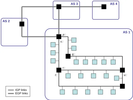
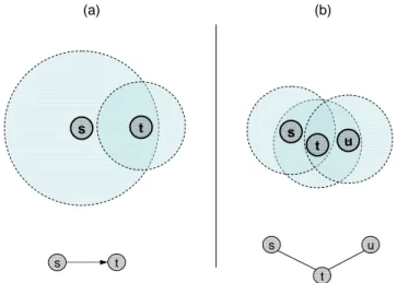
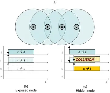
0.1 Visual map of the Internet as recorded by The Opte Project . . . 2 0.2 Two approaches for routing in an internetwork . . . 6 1.1 Circuit switching and packet switching networks . . . 16 1.2 Broadcast, wireless multi-hop and point-to-point networks. . . 19 1.3 Network architectures, graph and hypergraph representation. . . 21 1.4 IP address structure, for IPv4 and IPv6. . . 28 1.5 An IP link p : with network prefix p . . . 30 1.6 Connection of different Autonomous Systems. . . 35 2.1 Coverage and interference areas of an interface . . . 43 2.2 Hypergraph and graph representations of wireless networks . . . 45 2.3 The exposed node and the hidden node problems . . . 49 2.4 BSS modes of operation in IEEE 802.11 . . . 51 3.1 Compound Autonomous System. . . 60 3.2 Model for a MANET node. . . 62 3.3 Establishment of bidirectional communication via Hello exchange . . . 64 3.4 An Autonomous System composed of different routing domains . . . 68 3.5 Path suboptimality due to the presence of several routing domains in the same AS. . 69 4.1 Construction of the routing table based on information from the LSDB . . . 74 4.2 Mobility and neighborhood change in an ad hoc network. . . 76 4.3 Example of compound (wired/wireless) network. . . 82 5.1 Wireless collision caused by reaction to a common input. . . 87 5.2 Wireless collision caused by synchronization in periodic packet transmissions. . . 88 5.3 Forwarding algorithm with jitter. . . 90 5.4 Illustration of packet cases, for jitter analysis. . . 92 5.5 Node model. . . 93 5.6 Illustration of the traffic model for packets containing messages to be forwarded. . . 97 5.7 PDF and CDF of X(i), for i = 1, 2, 3, 4, 5, T = 0.1sec . . . 99 5.8 PDF and CDF of X(i), for T = 0.1, 0.2, 0.3, 0.4, 0.5sec. . . 100 5.9 PDF of X(−i)|(−2T ≤ Tt(−i)< 0) and X(−i)|(−2T ≤ Tt(−i) < 0, X(−i) > 0). . . 102
5.10 CDF of X(−i)|(−2T ≤ Tt(−i) < 0) and X(−i) . . . 102
5.11 Traffic model for packets containing messages to be forwarded (upper bound) . . . . 104 xxi
5.12 CDF for Mk(T ) and Mk∗(T ), for T = 0.1, λg= 0.2 and different values of k. . . 105
5.13 CDF for the upper bound of Ttx(T ), for different values of λg . . . 108
5.14 CDF of M∗
k,l, for different pairs (k, l), for T = 0.1sec, λin= 4pktsec, λg = 0.2pktsec . . . . 113
5.15 CDF for the lower bound of Ttx(T ), for different values of λg . . . 115
5.16 Lower and upper bounds for E{Ttx(T )}. . . 116
5.17 Simulated avg time to transmission for λin= 4pkts , λg= 0.2pkts , for different T ’s . . . 118
5.18 Simulated λout and λinrates, for different values of T and a theoretical rate λin= 4pkts 119
6.1 Flooding example, with different flooding overlays for different sources . . . 124 7.1 Relations between Gabriel Graph, Relative Neighbor Graph, SLO and SLOT . . . . 134 7.2 Illustration of the Gabriel Graph and the Relative Neighbor Graph principles. . . 136 7.3 Difference between RNG and SLO principles . . . 138 7.4 The SLOT triangular elimination under unit link cost . . . 139 7.5 Average SLOT overlay density (links per router). . . 142 7.6 Average SLOT links change, for constant speed s = 5m/s. . . 144 7.7 Grids for mobile and static scenarios . . . 145 7.8 Average density of SLOT overlay and full network overlay . . . 146 7.9 Density of SLOT overlays (SLOT-U and SLOT-D) in static networks . . . 147 7.10 Average link creation rate for SLOT and full network overlays . . . 148 7.11 Probability for a link of being selected under SLOT-U and SLOT-D variations . . . 154 8.1 Pure flooding vs. flooding based on the Multi-Point Relays (MPR) principle . . . 158 8.2 MPR recalculation due to changes in the 2-hop neighborhood . . . 161 8.3 Average delay for the inclusion of a 2-hop neighbor in the MPR computation . . . . 162 8.4 Density of MPR overlays for a static, error-free network . . . 165 8.5 Examples of disconnection in the MPR set . . . 165 8.6 Average link lifetime for MPRs and bidirectional neighbors . . . 167 8.7 Non-persistent and persistent approaches for link synchronization . . . 168 8.8 Path MPR malfunctioning example, with respect to router (1). . . 172 8.9 Block diagram for a MPR-based topology selection algorithm . . . 173 8.10 Enhanced Path MPR operation over the 2-hop neighborhood of router x. . . 174 9.1 Smart Peering (SP) flowchart . . . 179 9.2 Scenario of Proposition 9.2. . . 182 9.3 Scaled functions si(v) and number of performed synchronizations in Prop. 9.2 . . . . 183
10.1 Amount of ASNs assigned by RIRs to ISPs and end users . . . 190 10.2 Link hierarchy in OSPF. . . 193 10.3 Areas, interfaces and neighbors of an OSPF router . . . 194 10.4 Area partition of an Autonomous System under OSPF. . . 197 10.5 Example of virtual link between ABRs in OSPF . . . 198 10.6 Finite States Machine (FSM) for network interfaces in OSPF. . . 199 10.7 Finite States Machine for neighbors in OSPF. . . 200 10.8 Election of Designated Router (DR) for a broadcast or NBMA interface . . . 204 10.9 Non-broadcast network with no direct communication between every pair of interfaces 206 10.10Area partition of an Autonomous System under IS-IS. . . 208 10.11Routing level and area partition of the IS-IS network example of Figure 10.10. . . . 210 11.1 Link hierarchy in OR/SP. . . 219
11.2 Link triangles and multi-triangles around nodes a and b. . . 224 11.3 Overlays maintained by a router x in a static grid network: Path MPR, N2(x) and SP 226
11.4 Link hierarchy in MPR+SP. . . 227 12.1 Differential and incremental behavior in case of Hello transmission failure . . . 235 12.2 Impact of optimization mechanisms in Hello traffic (%). . . 236 12.3 Average size of the MPR set, average relay lifetime and LSA retransmission ratio . . 238 12.4 LSA retransmission ratio, depending on the link quality (30 routers), 5m/s . . . 239 12.5 Path length and user data traffic, for 5m/s . . . 241 12.6 Data delivery ratio and total traffic (data + control) in the network (30 nodes, 5m/s) 242 12.7 Adjacencies per node and adjacency lifetime, depending on the number of nodes . . 243 12.8 Average size of Hello packets (fixed grid, 5 m/s). . . 245 12.9 Adjacencies per node and adjacency lifetime, depending on the link quality . . . 246 12.10OSPF keep-alive (InactivityTimer ) impact in adjacency lifetime. . . 246 12.11Control traffic overhead (# packets and kbps) . . . 248 12.12Total (data + control) traffic, in kbps (5m/s, with 1M bps of data traffic load). . . . 249 12.13Delivery ratio and end-to-end packet delay (5 m/s) . . . 250 12.14Adjacencies per node and adjacency lifetime, for different persistent approaches . . . 251 12.15Total control overhead and LSA retransmission ratio (5 m/s) . . . 252 12.16Flooding and synchronization control traffic (# packets, 5 m/s) . . . 253 13.1 Computers position over the plan of LIX. . . 259 13.2 Considered topologies for scenarios I, II and III. . . 260 13.3 PDR of UDP flows and RTT of ICMP requests w.r.t. number of wireless hops . . . . 263 13.4 Control traffic overhead at server:eth1. . . 264 13.5 Control traffic overhead at wless3:wlan0. . . 265 13.6 Control traffic overhead at hybrid1:eth1. . . 266 13.7 Control traffic overhead at hybrid1:wlan0. . . 267 13.8 Wireless access to the Internet in the United States . . . 272 B.1 Illustration of the two-ray propagation model. . . 302 E.1 Impact of the α parameter in the probability of successful reception, for r = 150m. . 309
1.1 The OSI and the TCP/IP network reference models. . . 32 5.1 Traffic model variables. . . 93 6.1 Summary of overlay requirements. . . 123 6.2 Variables of the analysis. . . 127 10.1 LSA formats in OSPF. . . 202 11.1 Considered MPR-OSPF variations. . . 223 13.1 Network interfaces of testbed computers. . . 258 13.2 MPRs selected by each wireless interface, for each scenario. . . 261 13.3 Characteristics of transmitted UDP flows. . . 262 C.1 IEEE 802.11 family of standards . . . 303 E.1 General Simulation Parameters. . . 308 E.2 RFC 5820 (OR/SP) Specific Parameters. . . 308 E.3 MPR-OSPF (and Variations MPR+SP and SLOT-OSPF) Specific Parameters. . . . 309 F.1 Characteristics of transmitted UDP flows. . . 312 F.2 General Simulation Parameters. . . 313
Since the first computer networks appeared in the nineteen-sixties, two trends have been present in the evolution of computer networking. The first trend is related to the increase of the number of users that can exchange information or access to contents by way of computer networks – that is, which and how many computers are involved in communication. The second trend is set towards broadening the range of situations in which communication can be established among a set of user devices – that is, when, where and how communication is enabled over a computer network.
Spread and Growth of Computer Networks: Internetworking and the Internet
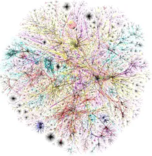
The first trend has led to the spread and growth of computer networks, on one hand, and the development of internetworking, on the other. Internetworking consists of interconnecting existing computer networks in such a way that users attached to any of these networks can interact with users from any other. In particular, communication between users is possible even when they are attached to networks based on different technologies. The main example of internetworking is the Internet itself, a world-wide collection of interconnected networks that enables communication among hundreds of millions of computers and users1. Figure 0.1 shows a simplified representation
of the way that networks are connected to each other through the Internet2. Each point in the
1According to the Internet Domain Survey Count (July 2010), http://www.isc.org/solutions/survey, the
In-ternet is estimated to integrate more than 750 million hosts connected through different networks.
2Image from The Opte Project, http://opte.org. The figure traces the path through the Internet followed by
packets sent from a single computer towards every Class C networking block – that is, within the range of IPv4 addresses between 1.0.0.0/24 and 255.255.255.0/24. Such paths are monitored by way of the traceroute utility. The Internet architecture and the IPv4 addressing model are described in chapter 1 of the manuscript.
picture represents a network able to contain a maximum of 254 computers. The picture provides a simplified view of the Internet topology, as networks represented as points may be divided, in turn, in several subnetworks.
Figure 0.1: Visual map of the Internet recreated by The Opte Project (data from November 2003).
The exchange of information between distant users through the Internet is performed through a complex networking infrastructure, that involves the following:
• A large number of inter-network high-capacity connections, sometimes referred as the Internet backbone.
• The Internet core protocols which are a set of common rules for information transmission and forwarding.
• The activity of a number of global entities (such as ICANN-IANA3, IETF4 and others) that
provide global management, interoperability, administration and standardization services for the Internet.
3ICANN: Internet Corporation for Assigned Names and Numbers; IANA: Internet Authority for Assigned Numbers. 4The Internet Engineering Task Force.
Unlike other world-wide network infrastructures (such as telegraph or analogue telephone network), the Internet infrastructure enables users to send and receive natively (i.e., without modems) any kind of digital information – not only voice or alphanumerical characters.
More Flexible Computer Networks: Ad hoc Networking
The second trend in computer networking focuses on requirements for setting up a computer network. The first computer networks were based on three main assumptions: (i) computers were mostly connected through wires; (ii) the topology was static, meaning that the way that computers were connected to each other was not supposed to change, and (iii) this topology was known in advance. Under these assumptions, interaction between a computer and the rest of the network was performed through a predictable and stable set of neighbors with which the computer could communicate directly. In case of topology change, the intervention of a central authority (either human or automatic) was required to restore or establish connectivity. As the Internet was developed in parallel with these first computer networks, this type of interaction between computer and network was also assumed in the Internet.
These three assumptions were relaxed as computer networks became bigger and more com-plex. The growth of the Internet and the decentralization of its architecture implied that topology was not known and could not be longer handled in a centralized manner – instead, distributed rout-ing approaches were implemented in the Internet durrout-ing the 1980s and 1990s [117, 127]. Moreover, the use of wireless communications in computer networks started to spread in the 1980s, when unli-censed use of wireless spectrum bands – the Industrial, Scientific and Medical bands – was allowed by the US Federal Communications Commission (FCC). Computer networks based on wireless com-munication present more dynamic topologies, and this dynamism increases significantly if computers in the network are allowed to move. While computer networks became more popular, wireless com-munication became more widespread and computer mobility more common (e.g., in the context of embedded networking devices in smartphones or vehicles). Thus, the need of more flexible models for computer networking became unavoidable [92]. In the 1990s, the concept of Mobile Ad hoc
Net-working was introduced to address network dynamism – this revealed useful for computer networks in which the previously stated assumptions (i) to (iii) cannot be assumed.
The concept of Mobile Ad hoc Network (MANET) provides an abstract model for network-ing with the highest degree of flexibility with respect to such characteristics: MANETs are wireless networks, designed to operate when:
(i) the topology is not known in advance;
(ii) the topology may change in an unpredictable manner, at any time and at any rate (for instance because elements of the network are mobile relatively to one another); and
(iii) no network infrastructure (physical connections between computers, networking hierarchy or central authority) can be assumed to be available.
Computers in a MANET thus cannot count on a predictable and stable set of neighbors through which they can interact with the network, nor on a central authority to advertise topology changes. Instead, the fact that topology in ad hoc networks is dynamic implies that computers have to be able to interact with the network as a whole, by way of the sets of neighbors that are rechable at each particular time. For that, they need to rely on the cooperation of neighboring computers that are able to forward information over the network, that is, neighboring routers. Such cooperative interaction is necessary both for keeping track of topology changes, and for enabling communication even when the set of available neighbors cannot be accurately determined.
Ever since the IETF formally defined MANETs in 1997 [89], envisioned applications of such networks have ranged from wireless sensor networks to vehicular networks, also including emergency and military deployments. Routers of a wireless sensor network [27, 61], for instance, are usually spread arbitrarily and thus produce static multi-hop topologies that cannot be predicted a priori. In Vehicular Ad Hoc Networks (VANETs) [68], topology changes rapidly due to high relative speed between devices installed in moving vehicles. In cases of recovery deployments for catastrophes or natural disasters (earthquakes, flooding, etc.) or military deployments, topology may also be dynamic and networking devices cannot rely on existing communication infrastructure because such
infrastructure may be damaged, destroyed or insecure. In all these cases, establishing communication presents challenges and issues.
Routing in Internetworks
The use of internetworking and ad hoc networking permits achieving two goals. Internet-working enables communication among an increasing number of users that are connected by way of a world-wide networking infrastructure, the Internet. Ad hoc networking, in turn, improves the capacity to establish network communication through computers that are deployed in a dynamic and non-predictable fashion.
Both quantitative and qualitative improvement of networking communication capabilities, can be achieved simultaneously by combining Mobile Ad hoc Networking and the Internet, that is, integrating ad hoc networks into the Internet architecture. This is the problem explored in this manuscript. Internetworks that result from such combination are those that support ad hoc properties in (parts of) their topology while being capable of communicating through the Internet infrastructure. As these internetworks present the same flexibility properties as MANETs in at least parts of their topology, they can be used for the very same purposes, e.g. vehicular communications, decentralized sensor deployments, etc. The fact that these internetworks are connected or embedded into the Internet by way of fixed networks implies that they can also be used for additional purposes – user Internet access, social networking, geographic services and such.
This manuscript restricts to the problem of routing within such internetworks: building and maintaining routes through which data can be sent from and towards computers in the internetwork. More precisely, the manuscript addresses the setting-up of mechanisms for enabling communication and information exchange (i) between computers from within one of the networks part of the in-ternetwork, and (ii) between computers from one network and the rest of the internetwork. Such mechanisms are needed to ensure that information is routed successfully within the internetwork.
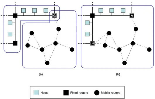
Figure 0.2 illustrates the two approaches possible for such internetworks. As routing prop-erties of ad hoc networks and fixed networks differ significantly, a natural approach consists of
G
(a)
H
H
(b)
Hosts Fixed routers Mobile routers
Figure 0.2: Two approaches for routing in an internetwork containing ad hoc networks and fixed networks connected to the Internet: (a) two routing domains, one for the fixed network and another for the ad hoc network, connected through a gateway G, and (b) one single routing domain that contains the ad hoc and the fixed networks of the internetwork, which are connected through two H routers. While it is possible to use more gateways in (a) in order to improve connectivity between domains, each additional gateway G is costly due to the specific hardware and routing configuration required for these gateways, together with the additional complexity introduced in the internetwork. This is not the case in (b), as H routers do not need capabilities other than those from the rest of routers.
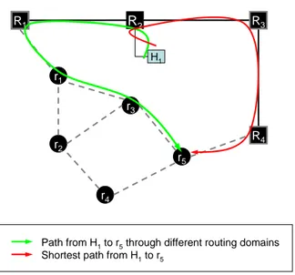
treating ad hoc and fixed networks as separate routing domains, with each routing domain being a part of the internetwork in which routers use the same instance of a routing protocol (Figure 0.2.a). The fixed networks that provide access to the Internet may use one of the Internet routing protocols, as OSPF5 or IS-IS6, while the attached MANET(s) may use instances of a specific protocol
opti-mized for ad hoc operation, such as OLSR7or AODV8. The use of different routing protocols in the
same internetwork makes necessary the presence of gateways, denoted G in Figure 0.2.a. Gateways are specific routers that ensure the exchange of routing information between the different routing
5Open Shortest Path First protocol [107].
6Intermediate System to Intermediate System protocol [122]. 7Optimized Link-State Routing protocol [71].
domains in the internetwork, and therefore participate in both the ad hoc and the fixed networks, and they provide support for the different involved routing protocols.
This approach has three main drawbacks. First, the use of different protocols in the same internetwork is more difficult to handle than the use of a single protocol, and thus also more expensive in terms of hardware/software requirements, network maintenance and configuration. Second, gateways cause an additional level of complexity in terms of management and routing of the whole internetwork. This additional level of complexity comes from the fact that gateways need to be able to distribute the necessary routing information among different networks, in order to ensure that computers in any part of the internetwork can communicate. As these tasks typically involve specific hardware and software for gateways, such complexity also implies higher costs. Third, inter-network routes are not necessarily optimal, even if the involved routing protocols are designed to provide optimal paths in their respective domains. In the case of several routing domains, routes traversing gateways consist of the juxtaposition of several (at least two) “locally” shortest paths (optimal in each routing domain traversed by the route), which does not necessarily lead to a “globally” shortest path (in the whole internetwork). Moreover, these drawbacks cannot be simultaneously minimized, as they are closely intertwined: reducing the number of gateways, while alleviating the additional complexity and costs, may damage significantly the quality of the performed routes (suboptimality).
Instead of separate routing domains, this manuscript explores the second approach, il-lustrated in Figure 0.2.b. This approach seeks to address these drawbacks by developing a single routing domain in the internetwork that contains both ad hoc networks and fixed networks, and is thus handled by a single routing protocol in a single routing domain. The use of a single protocol in the internetwork implies that gateways are no longer necessary, and that route computation is performed over the whole internetwork, therefore improving the quality of the selected routes. With this approach, the role of gateways is fulfilled by simple routers, which have interfaces both to ad hoc and fixed routers, and use the same routing protocol as any other router in the routing domain.
Link State Routing in Compound Internetworks
Internetworks that combine ad hoc and Internet fixed networks are denominated compound internetworks throughout this manuscript, which explores a single routing protocol for such internet-works. In this context, routing can be performed by way of different techniques. The main protocols used for routing within Internet fixed networks are, however, all based on the link-state technique [100]. This manuscript explores and analyzes the use of this link-state technique for routing in compound internetworks, not only for the fixed networks but also for the (mobile) ad hoc networks of the internetwork.
Link-state algorithms are based on the assumption that routers acquire and maintain infor-mation about the topology of the network in which they are used – this inforinfor-mation forms the Link State Database (LSDB) of the network. This information is disseminated over the network through a local-to-global distributed procedure: routers describe their local topology and flood these descrip-tions to the whole network. By receiving topology descripdescrip-tions and updates from every other router in the network, any router is able to maintain a complete description of network topology. Based on this description, routers compute the best (shortest) paths to every possible destination in the network – Dijkstra’s algorithm [135] is used to determine such shortest paths.
OSPF and IS-IS protocols are the main examples of link-state routing protocols for networks in the Internet. The two protocols are similar in several aspects: both have a modular architecture, meaning that they are able to support different extensions for specific networking properties, and different extensions may coexist in the same routing domain while using the same core mechanisms. Also, both have been designed for wired networks with static topologies and therefore are not adapted to the challenges and restrictions of wireless ad hoc networking. For instance, control traffic generated in standard OSPF and IS-IS operation, while manageable in the context of wired and fixed networks, becomes excessive in wireless ad hoc networks in which bandwidth is severely limited. In order to be applicable in ad hoc networks, these link-state protocols need therefore to be adapted in their operation to accommodate the new restrictions and features that are present in such networks.
This is the approach that is developed throughout this manuscript. Taking advantage of modular architecture, the extension of already existing Internet link-state routing protocols for operation in MANETs is explored. The objective of such an extension is two-fold. First, to minimize changes in the routing infrastructure of fixed networks already in use inside a compound internetwork. Second, to obtain an extended protocol that can be used as single routing protocol for all networks (fixed and ad hoc) of a compound internetwork. The extended protocol should be therefore able to accommodate the properties and issues of ad hoc networking in the Internet without requiring substantial changes in the routing mechanisms already used for Internet networks.
Network Overlays in Link State Routing
In order to ensure accuracy and consistency of topology information maintained by routers running a link-state protocol, different operations need to be performed over the network. Such operations are related to the advertisement of topology changes to all the routers in the network: description, flooding and synchronization of LSDB. In ad hoc networks, these operations are per-formed in a distributed fashion, meaning that routers autonomously take the decisions required to execute each of such operations. The way to perform these operations needs to take into account the properties and limitations that prevail in MANETs: in this manuscript, link-state operations are treated separately due to significant differences between such operations, in terms of goals, scope, involved routers and impact in the network. The manuscript introduces the concept of a network overlay, to be associated with each link-state operation, and proposes an analysis of the link-state routing technique and each of their related operations in terms of such overlays.
A network overlay is a network built on top of an existing computer network. In literature, a network overlay usually denotes an abstraction layer in which an underlying networking infras-tructure (one or more computer networks already existing and enabling communication between any pair of attached computers) is used to provide specific communication services between computers of the network [21]. In such cases, the topology of the network overlay may be independent from the topology of the underlying network: any topology is possible as far as the involved computers
are connected through the underlying network. The Internet itself can be understood as an overlay network, and other well-known examples include peer-to-peer (P2P) networks for file exchange [90], content distribution [95] or multicast video-conference services [96].
In this manuscript, however, the term of overlay is used in a slightly different sense. Rather than an arbitrary topology built on top of an existing networking infrastructure, a link-state overlay over a MANET includes some of the computers attached to the network and uses some of the available links between such computers to perform one of the above-mentioned link-state operations. For each of these operations, the manuscript explores requirements and recommended properties that the associated overlay should satisfy. Based on this exploration, the underlying trade-offs for different operations are identified, and several distributed techniques for building and maintaining link-state overlays are examined and compared.
Identification of link-state operations and separate analysis of the corresponding link-state overlays permit independent optimization of the performance of each of the associated link-state operations. Such optimizations apply to MANET extensions of modular link-state protocols. An extended protocol that uses one of such extensions can then be used for routing in compound internetworks. While this manuscript focuses on the particular case of OSPF, the performed analysis and the presented arguments can be generalized to other Internet link-state routing protocols, such as IS-IS.
Structure and Overview
This manuscript is organized in three Parts. The main concepts and elements of networking are presented in Part I. Chapter 1 introduces basic concepts related to computer networks (interface, link, network, routing) and presents a brief overview of the notion of internetworking and the Internet addressing and routing architecture. Chapter 2 concentrates on the specific case of wireless networks, pointing out the impact that the use of radio channel has in terms of network communication. Chapter 3 analyses the issues and challenges that arise in the context of wireless multi-hop ad hoc networks, a particular class of wireless networks. This chapter also presents and discusses the
implications of the notion of compound Autonomous Systems, as the result of embedding ad hoc networking into the traditional Internet networking framework.
Part II studies the implementation of link-state routing mechanisms for (mobile) ad hoc networks. Chapter 4 describes the characteristics and operations related to link-state routing, first, and identifies the most relevant issues that need to be addressed for performing link-state routing, second. Chapter 5 elaborates on the problem of packet collisions due to simultaneous retransmissions during flooding in wireless networks, and analyzes (both theoretically and through simulations) the impact of jittering. This technique consists of distributing, over time, wireless retransmissions of the same packet, in order to avoid collisions. Chapter 6 introduces the concept of a link-state overlay associated to a link-state operation, and identifies the required properties for each link-state overlay based on the characteristics of its associated operation. The analysis in this chapter provides the criteria to examine, evaluate and compare the different link-state overlay techniques proposed in following chapters. Chapter 7 proposes the Synchronized Link Overlay (SLO) technique and presents a theoretical analysis of the properties of its associated network overlay, focusing on its density and the stability of their links. Most results presented in this chapter are published in [14] and in [10]. Chapter 8 focuses on the Multi-Point Relaying (MPR) technique [88]. Although MPR is primarily used for flooding purposes, the chapter explores the applicability of MPR and MPR-based techniques for other link-state operations, LSDB synchronization and topology selection. The discussion and analysis of techniques based on MPR for topology selection purposes is published in [12]. Finally, chapter 9 studies the Smart Peering technique and discusses its applicability as a synchronization technique, some of the presented results being included in [4]. A summary of the main results presented in this Part was published also in [3].
Finally, Part III applies the previously presented techniques to OSPF, one of the main Internet link-state routing protocols. Chapters in this Part evaluate the performance of these tech-niques as extensions of OSPF for ad hoc networks, and studies the extended OSPF protocol as a candidate for link-state routing in compound internetworks, based on network simulations and a real testbed. Chapter 10 describes the operation and architecture of OSPF, as well as some significant
aspects of IS-IS, in order to identify similarities between both protocols. Chapter 11 examines some existing extensions of OSPF for MANET operation, and proposes some additional improvements based on the analysis deployed in Part II. Presented extensions include those standardized by the IETF: RFC 5449 [24], RFC 5614 [22] and RFC 5820 [19]. Proposed additional extensions include MPR+SP, based on the combination of RFC 5449 and RFC 5820, presented and evaluated in [4]; a variation of RFC 5449 that uses the SLOT technique for synchronization (SLOT-OSPF, evaluated in [10]); and some additional variations of RFC 5449 that explore use of link persistency in differ-ent link-state overlays. Chapter 12 performs an analysis of the main aspects that are required for a MANET extension of OSPF based on comparison via simulation of the presented extensions. Results and experiments described in this chapter have been published in different papers, in particular [20] and [13] for the comparison between RFC 5449 and RFC 5820, and [11] for the impact of MPR link change rate and different persistent strategies in RFC 5449. Chapter 13 completes these analysis by describing set-up, operation and experiments of a testbed, composed of a wired and a wireless network, in which routing is performed by way of OSPF extended with the MPR-OSPF extension for wireless interfaces; results from these experiments have been documented in [1].
The final chapter concludes this manuscript by presenting and summarizing final results, their implications and perspectives for future work.
NETWORKING
FUNDAMENTALS
Computer Networks
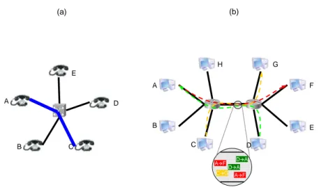
In 1962, L. Kleinrock introduced networking based on packet switching [134]. Before that, communication between two points (nodes) was only possible by establishing a persistent electri-cal circuit between them, through which data could be sent. That was the principle of the Public Switched Telephone Network (PSTN), where a set of terminals or endpoints (typically, but not only, telephones) were connected through a set of wires and telephone switches. These switches were responsible for establishing a persistent circuit between the calling terminal and the called terminal. Once the circuit was established, its use was exclusively reserved to the two connected endpoints. Such circuit (telephone call) was maintained until the end of the communication (e.g., voice con-versation), after which the connection was closed. Figure 1.1.a illustrates the main characteristics of PSTN calls: during the call between terminals A and C, no other terminal is able to establish communication with either A or C, as the circuit between A and C is persistent and exclusive.
Packet switching is based on a different approach (see Figure 1.1.b). Rather than com-municating by establishing persistent circuits between endpoints, the use of data packets permits using the same channel (e.g., a wire) to provide support for simultaneous communications between many different pairs of endpoints. Data to be sent from a source to a (set of) destination(s) is en-capsulated in data units, called packets, each of which can be treated autonomously and separately. These packets may need to be forwarded by one or more intermediate nodes before reaching their
A B C D E (a) A F A B C D E F G H D A C G A F D A (b)
Figure 1.1: Examples of (a) communication through circuit switching in PSTN, and (b) communi-cations through packet switching networking.
final destination(s).
This approach enables more flexible communication between nodes within a network than the circuit-switching approach, as it enables any endpoint to maintain several communications con-currently. By not dedicating the channel to a particular pair of endpoints, it also allows a more effi-cient use of the channel. This is at the expense of lowering reliability of communication: packets in a packet-switching network may be lost or delivered out of order. Characteristics of circuit switching are appropriate for requirements and properties of voice transport (reliable communication, delivery of data in the same order in which it was sent, balanced amount of data in both directions); packet switching, in turn, has become the basis of computer networking, and in particular the Internet.
1.1
Outline
This chapter presents the main elements of computer networks and the Internet. Section 1.2 presents the basic terms and concepts of computer networking – network, interface, link, routing and routing protocol. While many terms are in common use in networking research, they are defined formally in this section in order to avoid ambiguity and clarify the precise meaning and the sense in which they are employed throughout this manuscript. Section 1.4 addresses the interconnection of
existing networks (internetworks), presents the concept of internetworking and provides an architec-ture overview of the most prominent case of internetwork – the Internet. In particular, the section describes the IP addressing model and the Internet routing hierarchy. Finally, section 1.5 concludes the chapter.
1.2
Networking and Routing Concepts
This section presents and discusses the basic elements of computer networking. Section 1.2.1 defines the concepts of packet, computer network, interface and link. Section 1.2.2 presents the graph representation of a network and discusses its interest as analysis tool. Based on these definitions, section 1.3 elaborates on the conditions that need to be fulfilled in a computer network so as to ensure that information can be exchanged between computers.
1.2.1
Networks and Links
A computer network is defined as follows:
Definition 1.1 ( Packet computer network ). A computer network is a set of two or more computers that are connected in such a way that every pair of computers can exchange information. A packet computer network or packet-switching computer network is a computer network in which information is exchanged by means of packets, i.e., data units that contain sufficient information about their source and destination(s) to be routed and delivered separately through the network. Unless otherwise specified, all references to networks relate to packet computer networks.
Computers are connected to other computers in a network through links.
Definition 1.2 ( Link between computers ). There is a link between two computers A and B, denoted by A −→ B, if and only if A is able to transmit data to B and B is able to receive such data, without intervention of any other computer.
Definition 1.3 ( Symmetric link between computers ). A link between two computers A and B is said to be symmetric (or bidirectional ), and denoted by A ←→ B, if and only if there are links
A −→ B and B −→ A, i.e., data can be transmitted from A and received by B and vice versa, without intervention of any other computer.
A computer participates in a link by way of a network interface:
Definition 1.4 ( Network interface ). A network interface of a computer is a device that provides access from that computer to a link through an underlying physical communication channel.
In this sense, link definitions 1.2 and 1.3 can be rephrased as follows, in terms of interfaces: Definition 1.5 ( Link between interfaces ). There is a link between two network interfaces a and b, denoted by a −→ b, if and only a is able to transmit data (bits) to b and b is able to receive such data, without the intervention of any other interface.
Definition 1.6 ( Symmetric link between interfaces ). A link between two network interfaces a and b is said to be symmetric (or bidirectional ), and denoted by a ←→ b, if and only if there are links a −→ b and b −→ a, i.e., data can be transmitted from a and received by b and vice versa, without requiring the intervention of any other interface.
The existence of a link between two computers implies the existence of (at least) one link between two network interfaces of these computers. Let A and B be two computers, and let I(A) and I(B) be the set of network interfaces of A and B, respectively; then,
A −→ B =⇒ ∃a ∈ I(A), b ∈ I(B) : a −→ b
Reciprocally, the existence of a link between two network interfaces implies the existence of one link between the computers to which the interfaces are attached. In this manuscript, the term link denotes a link between network interfaces, unless otherwise specified.
Unless stated otherwise, the term link in this manuscript denotes a symmetric link. Non-symmetric links are explicitly called aNon-symmetric links.
Depending on the number of interfaces in a link, different types of links can be distinguished. Figure 1.2 illustrates three different types of links and networks: broadcast links, point-to-point links and wireless links. The first two are defined in definitions 1.7 and 1.8; wireless links are described in chapter 2.
a b c d a b c d c a b a c b a b c d a b c d (a) (b) (c)
Figure 1.2: Examples of computer networks and links, with their network graph representations: (a) Broadcast network based on a single multiple-access link, (b) Wireless multi-hop network with several links, (c) Distributed network based on several point-to-point links. The existence of an edge between two vertices in a network graph implies that there is a link between the interfaces represented by such vertices.
Definition 1.7 ( Point-to-point link ). A link l between two network interfaces a and b is a point-to-point link if and only if data can be transmitted from a to b (and/or vice versa) by way of l and no other interfaces x and y (x 6= a, b; y 6= a, b) can exchange information through the same link l.
Definition 1.8 ( Broadcast link ). A link l is a broadcast link for a set of network interfaces {xi}i≤k if and only if data can be transmitted from xi to xj for any value of i, j ≤ k, and a packet
transmitted by any interface xi is received by every other interface in the network xj, j 6= i.
• Defs. 1.5 and 1.8 imply that links between different interfaces (e.g., a −→ b and c −→ d in Figure 1.2.a) may correspond to the same broadcast link. For a criterion to identify equivalent links, see the link equivalence relation presented in Appendix A.
• Broadcast links are always symmetric: for any interfaces a and b attached to such a link, data can be transmitted either from a to b or from b to a.
of link : both allow communication from one network interface to another through a physical com-munication channel – in the case of the broadcast link, in particular, information can be exchanged between any pair of attached network interfaces. Examples of point-to-point links include PPP1
(see Figure 1.2.c), while the most prominent examples for broadcast networks include Ethernet and Token-Ring technologies (the architecture of a broadcast network is displayed in Figure 1.2.a).
Broadcast and point-to-point categories do not cover all possible cases of link. Commu-nication between wireless network interfaces, in particular, cannot be modeled in general by any of these two definitions: in the example of Figure 1.2.b, the wireless link between b and c is not a point-to-point link (as packets sent from b to c are also received by a) and neither is a broadcast link (in particular, a cannot receive packets sent by c). Properties and challenges of wireless links and networks are discussed in detail in chapter 2.
1.2.2
Graph and Hypergraph Representation
The topology of a computer network at a particular point of time can be represented as a graph G = (V, E), in which the set of vertices V corresponds to the set of attached computers and the set of edges V indicates the presence of links between computers. Such graph G is called network graph throughout this manuscript, and is assumed to be connected – otherwise, G denotes the network corresponding to a connected component of the graph instead. Given two vertices x and y of V , the edge xy is included in E if and only if there is a link between computers represented by x and y. Asymmetric links are represented by directed edges, while symmetric links correspond to undirected edges.
The graph representation of a network is useful for a number of purposes, and is used throughout this manuscript to analyze properties of networking and routing algorithms from a theoretical perspective. For instance, the path that a packet follows from a source computer, x, to a destination computer, y, can be represented as a path through the network graph, pxy.
Definition 1.9 ( Network path ). A network path between two vertices x, y ∈ V in a network
graph G = (V, E) is a collection of edges of E, pxy = {xm1, m1m2, ..., mk−1y} such that every pair
of contiguous edges have one vertex of V in common. Given pxy, |pxy| = k denotes the length of
the path, that is, the number of hops of the path.
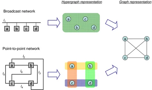
However, the graph abstraction has some significant limitations that need to be taken into account. The most relevant is that different edges in a network graph do not necessarily indicate different links in the network: the same link may be represented by several (at least one) edges. Figure 1.3 illustrates some implications of this fact: networks with different architectures may present equivalent graphs.
c b a d a b c d a c b d l1 l2 l3 l4 l5 l6 Broadcast network Point-to-point network a c b d a c b d
Hypergraph representation Graph representation
Figure 1.3: Two networks with different architectures and different number of links may have the same graph.
For networks in which the number of interfaces (computers) participating in a link can be higher than two, such as broadcast or wireless networks, links do not necessarily correspond to edges and therefore, the graph representation cannot be used for analyzing aspects such as collisions or available bandwidth in a shared medium. The properties of wireless and mobile communication, in particular, impose additional constraints to the validity of network graphs, that are discussed in chapters 2 and 3.
hypergraph may be useful, in particular for wireless ad hoc networks [23]. A network hypergraph is a pair H = (X, ˜E) where X denotes the set of vertices and ˜E denotes the set of hyperedges. Vertices from X correspond, as for network graphs, to computers attached to the network; an hyperedge ex ∈ ˜E, where x ∈ X, contains all the vertices corresponding to computers that receive
a transmission from computer x, x itself included – in this sense, it generalizes the notion of edge, which is a particular case of hyperedge that only contains two vertices. Formally, an hyperedge ex
is a subset of the hypergraph vertices (ex ⊆ X). Given that the number of vertices included that
an hyperedge may contain is not restricted to two, hypergraphs are able to capture more accurately than graphs the connectivity and collision issues in networks where links may involve more than two interfaces.
1.3
Addresses, Direct and Indirect Communication
Communication between computers connected through links and networks may require that the interfaces involved in communication can be identified without ambiguity. These identifiers are called addresses.
For links that connect two and only two interfaces (point-to-point links), sender and receiver of a particular packet can be identified by the receiving interface even in the absence of addresses: there is no other possible receiver than itself, and there is no other possible sender than the other interface in the link. For links involving more than two interfaces, however, an interface identity is required. This identity, sometimes called physical address, has to be unique within the link in order to enable unambiguous communication with the rest of interfaces in the link.
The transmission of packets from one interface to another in a network requires that:
(i) interfaces have a unique address in the network (network layer address), so that source and destination(s) of packets can be unambiguously identified by including such addresses in the packets2,
(ii) interfaces agree in the formats and procedures to communicate (network technology).
These two conditions are sufficient for enabling communication between network interfaces in the same link: packets are then delivered in a single hop, i.e., in the same link that they were transmitted. When two interfaces do not participate in the same link, packets between them need to be routed across the network by intermediate computers, that is, sent from the link in which they were first transmitted to a link in which they are received by their destination.
Computers able to perform such forwarding operation between different links are called routers (or intermediate systems), and those that process information as senders or final receivers are called hosts (or end systems). Computers can behave simultaneously as hosts and routers as far as they have interfaces attached to (at least) two links and are able to make forwarding decisions [116].
Therefore, communication between interfaces that do not participate in the same link (indirect communication) requires the following additional conditions:
(iii) in case they have multiple interfaces, hosts must be able to determine to which interface (and thus, to which router) packets need to be sent.
(iv) routers must be able to forward packets to their final destination, if there is a link to it, or to a router that is closer3 to the final destination.
Equivalently, hosts and routers in a network must be able, for any packet, to deliver it to a link to which its destination is attached, or to determine the next hop towards its destination. The maps between possible destinations and next hops are called routing tables. In case of hosts, the routing table indicates as next hops routers that are reachable through each of the available interfaces. Routing tables from hosts and routers also contain information about the links to which they are able to deliver (and forward, in case of routers) packets. Information collected in the set of routing tables enables thus the communication between computers with interfaces not attached
to a common link; such information is maintained and updated in the routers by way of a routing protocol.
For stable networks that contain a small number of hosts and routers, routing tables can be filled and maintained manually, with human operation (static routing). As the network grows, and changes in the topology are more frequent (for instance, due to router failures), routing tasks become more complex and dynamic routing protocols are needed.
Definition 1.10 ( Routing protocol ). A routing protocol is a set of procedures performed over the network in order to collect routes and maintain the routing tables of the routers in the network, so that they enable computers to transmit and successfully deliver packets to every possible destination in the network.
There are two main approaches to dynamic routing:
• Proactive routing. Routers collect topology information from the network and maintain proac-tively (i.e., regardless on whether they are used) routes towards all destinations. This way, routers are able to forward packets at any time to any destination in the network. Depending on how the information for such forwarding decisions is acquired, three approaches can be distinguished:
– Link state routing. Routers advertise the status of their links (link-state) to the whole network. This way, every router in the network receives the link-state of other routers in the network, maintains information about the whole network topology and is therefore able to locally compute network-wide shortest paths, usually by way of Dijkstra’s algo-rithm [135]. Examples of this approach are the Open Shortest Path First (OSPF, RFCs 2328 and 5340 [107, 28]) and the Intermediate System to Intermediate System (IS-IS, RFC 1142 [122]) protocols, as well as the Optimized Link State Routing protocol (OLSR, RFC 3626 [71]). OSPF and IS-IS are described in more detail in chapter 10.
– Distance-vector routing. A router shares its routing table only with its neighbors, indicat-ing its distance and the next hop towards any reachable destination. Neighbor distance is
defined according to the current link metric, which assigns a scalar cost to any available link in the network. By receiving the routing tables of all its neighbors, which in turn have been shared with the neighbors of the neighbors, a router is able to identify, for each advertised destination, the neighbor that provides shortest distance and select it as next hop. Distance-vector protocols mostly use the distributed Bellman-Ford algorithm [136, 133] to identify network-wide shortest paths. The Routing Information Protocol (RIP, RFCs 1058 [124], 2080 [110] and 2453 [102]) is a prominent example of this family. – Path-vector routing. Based on the same principle as distance-vector routing, a router advertises to its neighbors the paths to all reachable destinations. Each path is described by indicating the routers that are traversed. This way, local distribution of locally main-tained paths enables all routers in the network to build routes to all possible destinations. The most prominent example of this family of protocols is the Border Gateway Protocol (BGP, RFC 1771 [117]).
• Reactive routing. A router calculates routes to a destination only when it receives information addressed to that destination and it is not known (i.e., the routing table does not provide a next hop). Dynamic Source Routing (DSR, RFC 4728 [38]) or Ad hoc On-Demand Distance Vector (AODV, RFC 3561 [75]) are examples of reactive routing protocols.
The main advantage of proactive algorithms when compared to reactive algorithms is that all routes are immediately available for proactive routers when the network has converged, which reduces the delay for data traffic with respect to reactive routing protocols. Such immediate avail-ability of routes requires, however, that topology information is flooded periodically over the network and independently from the data traffic load.
Among proactive algorithms, distance-vector and link-state are the main types of algo-rithms [100] – path-vector algoalgo-rithms being a variation of distance-vector. Distance-vector protocols were used in the early stages of computer networking, but were replaced gradually by link-state protocols in the Internet. The reasons for this replacement were the existence of problems in distance-vector algorithms, in particular the well-known count-to-infinity problem [70] (which does
![Figure 1.5: An IP link p : with network prefix p. IP addresses of computers in this IP link have the structure p : i/[p], for 0 < i < 2 [p] .](https://thumb-eu.123doks.com/thumbv2/123doknet/2653182.60086/59.918.272.597.165.246/figure-link-network-prefix-addresses-computers-link-structure.webp)