This is an author-deposited version published in :
http://oatao.univ-toulouse.fr/
Eprints ID : 7943
To link to this article : DOI: 10.1109/TSTE.2010.2046685
URL :
http://dx.doi.org/10.1109/TSTE.2010.2046685
O
pen
A
rchive
T
OULOUSE
A
rchive
O
uverte (
OATAO
)
OATAO is an open access repository that collects the work of Toulouse researchers and
makes it freely available over the web where possible.
To cite this version :
Tran, Duc-Hoan and Sareni, Bruno and Roboam, Xavier and
Espanet, Christophe
Integrated Optimal Design of a Passive Wind
Turbine System: An Experimental Validation.
(2010) IEEE
Transactions on Sustainable Energy, vol. 1 (n° 1). pp. 48-56. ISSN
1949-3029
Any correspondence concerning this service should be sent to the repository
administrator:
[email protected]
Integrated Optimal Design of a Passive Wind Turbine
System: An Experimental Validation
Duc-Hoan Tran, Bruno Sareni, Xavier Roboam, Member, IEEE, and Christophe Espanet
Abstract—This work presents design and experimentation of a full passive wind turbine system without the active electronic part (power and control). The efficiency of such a device can be ob-tained only if the system design parameters are mutually adapted through an integrated optimal design method. This approach, based on multiobjective optimization, aims at concurrently opti-mizing the wind power extraction and the global system losses for a given wind speed profile while reducing the weight of the wind turbine generator. It allows us to obtain the main characteristics (geometric and energetic features) of the optimal Permanent Magnet Synchronous Generator (PMSG) for the passive wind turbine. Finally, experiments on the PMSG prototype built from this work show a good agreement with theoretical predictions. This validates the design approach and confirms the effectiveness of such a passive device.
Index Terms—Genetic algorithms, integrated optimal design (IOD), multiobjective optimization, passive wind turbine.
NOMENCLATURE
Power coefficient factors. Electrical half pole width. Airgap/Remanent/Yoke induction. Wind turbine power coefficient. Rotor/Stator yoke thickness. Slot depth.
DC equivalent electromotive force (EMF), phase EMF.
Wind energy.
Wind turbine damping coefficient. Airgap width.
Optimization constraint . Phase current.
DC current in the battery.
D.-H. Tran, B. Sareni, and X. Roboam are with the Université de Toulouse, Laboratoire LAPLACE, UMR 5213 CNRS-INPT-UPS, 31071 Toulouse Cedex, France (e-mail: [email protected]; [email protected]; [email protected]).
C. Espanet is with the University of Franche-Comte (UFC), FEMTO-ST In-stitute, CNRS UMR 6174, ENISYS Department, 90010 Belfort, France (e-mail: [email protected]).
Current density. Wind turbine inertia. Winding factor. Carter coefficient. Slot filling coefficient. Magnet thickness.
Permanent Magnet Synchronous Generator (PMSG) active length.
Main/Leakage/Stator inductance. Tip speed ratio.
Magnet permeability.
Number of conductors per slot. Number of slots per pole per phase. Base/Wind turbine rotation speed. Base/Useful power.
Conduction/Iron/Joule/Mechanical loss. Number of pole pairs.
Air density.
Slot depth bore radius/Radius length ratio. Equivalent armature bore radius.
Blade radius.
DC/Stator/Overlap resistance. Diode resistance.
Bore radius.
Electromagnetic/Wind turbine torque. Base/dc/phase voltage.
Wind speed.
DC equivalent/phase flux. Opening angle of a slot. Magnet/Slot/Tooth width.
I. INTRODUCTION
C
LOSE to high-power wind turbines for onshore or off-shore applications, small wind systems represent an interesting target for applications such as rural electrifica-tion and autonomous energy producelectrifica-tion networks for waterFig. 1. Fully “Passive” wind turbine system.
pumping, desalination. Optimizing energy efficiency generally leads to adaptation of the load impedance and consequently the speed of the generator with the wind turbine operating condi-tions. Many active structures have been thus proposed [1]–[15] to allow tracking the maximum power operation through corre-sponding maximum power point tracking (MPPT) strategies.
However, for such an application frame, the system cost has to be drastically minimized, for instance, by simplifying the struc-ture with PM synchronous generator feeding a diode rectifier associated with a battery bus. For grid-connected applications, impedance adaptation can be obtained through the grid inverter as in [13].
In earlier studies [16], [17], we proposed a very “low-cost” and more reliable structure for remote applications without an active control unit and with a minimum number of sensors (see Fig. 1). In fact, for such a device, a “natural” impedance adapta-tion can be achieved with the passive structure by optimizing the accordance between system parameters using an integrated op-timal design (IOD) approach. This approach has been success-fully applied in simulation for a small Savonius wind turbine of 300 W. In this paper, the same methodology is investigated on a passive system composed of 1.5-kW three-bladed wind tur-bine. The optimal Permanent Magnet Synchronous Generator (PMSG) resulting from the IOD process is validated from ex-periments on a real prototype.
II. MODELING OFTHEPASSIVEWINDTURBINESYSTEM
A. Wind Model
A typical wind cycle defined in terms of speed harmonic de-composition is taken for describing the wind speed behavior [15]
(1)
B. Wind Turbine Model
A three-bladed wind turbine of radius is considered in this study. It provides a wind power defined by [18]
(2) where the power coefficient varies as a function of the tip speed ratio according to Fig. 2. In particular, it can be interpolated by a seventh-order polynomial as follows:
(3)
Fig. 2. Three-bladed wind turbine with its power coefficient.
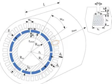
Fig. 3. PMSG geometric features.
where the values are given in Appendix C. The dynamic model of the turbine is represented by the following relation:
(4) where are, respectively, the wind and electromagnetic torques, and being the total wind turbine inertia and vis-cous damping coefficient [17].
C. PMSG Model
Two analytical models have been developed in order to char-acterize the electromagnetic behavior of the PMSG from its geo-metric features defined in Fig. 3.
1) 1st Model: This model has been derived from [19] and is presented in more detail in [17]. It considers a 1-D distribu-tion of the magnetic field in the airgap and the permanent magnet represented by a first-harmonic approximation. Be-cause of its simplicity and its low computational cost, it is used in the IOD process to optimize the PSMG.
2) 2nd Model: This model has been developed in [20]–[22]. It takes into account 2-D space harmonics of the mag-netic field distribution in the airgap and in the permanent magnet. Because of its better accuracy, this model is taken as a reference to validate the results obtained with the pre-vious simplified model.
Note that the electrical circuit parameters of the PMSG, i.e., phase flux, stator inductances, and stator resistances, can be ob-tained from both models as shown in Appendix A.
Fig. 4. Equivalent dc model of the PMSG rectifier association.
Fig. 5. Power balance in the passive wind turbine system.
D. Circuit Model of The Passive Wind Turbine System
In order to reduce the computing time of electrical values, a simplified dc equivalent model (called mixed-reduced model in [17]) has been proposed in [16] and [17] for representing the PMSG-Diode rectifier association (see Fig. 4). This model in-cludes the armature reaction in the generator and the diode over-lapping during the commutation interval. The correspondence between ac [root mean square (rms)] values and dc ones, in the PMSG circuit model is given in Appendix B.
III. MULTIOBJECTIVEOPTIMIZATION OF THEPASSIVEWIND
TURBINESYSTEM
In this section, the IOD of the PMSG is presented, converting the IOD problem into a multiobjective optimization problem.
A. Design Variables, Objectives, and Constraints
1) Design Objectives: Because of the “naturally small”
effi-ciency of the passive wind turbine, the first objective deals with the maximization of the average useful power during the wind cycle defined in (1). This power consists of the wind power extracted from the wind turbine reduced from all losses in the system. These losses include mechanical losses in the turbine, conduction losses in the diode rectifier, iron losses , and Joule losses in the PMSG. The power balance in the system is illustrated in Fig. 5. For more details about the calculation of these losses, we invite the reader to refer to [17]
(5) It should be noted that maximizing the useful power implies the maximization of the extracted wind power as well as the minimization of all losses in the system.
The second objective consists in the minimization of the total system mass which includes the wind turbine mass , the PMSG mass , and the radiator mass as-sociated with the diode rectifier
(6)
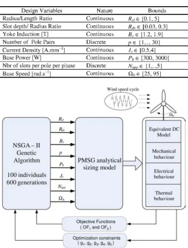
TABLE I DESIGNVARIABLES
Fig. 6. IOD process based on multobjective NSGA-II optimization.
The PMSG mass is evaluated from the mass of each components (iron, copper, magnet) and geometric features sim-ilar to [17] and [23]. The radiator mass of the diode rectifier is calculated from the radiator thermal resistance and the conduc-tion losses according to [17].
2) Design Variables: Design variables and their associated
bounds are mentioned in Table I. These variables should be op-timized in the IOD process in accordance with the design objec-tives defined in the last subsection.
3) Design Constraints: Five constraints are introduced to
en-sure the system feasibility in relation to the parametric varia-tion of design variables in the optimizavaria-tion process. These con-straints concern the number of copper winding per slots (higher than one and limited by the minimal section of winding con-ductors), the maximum temperature associated with the copper windings in the PMSG, the demagnetization limit of the mag-nets, and the maximum temperature in the semiconductor junc-tions of the diode rectifier. All details about the calculation of these constraints and the computation of thermal values in the PMSG and in the diode rectifier can be found in [17] and [23].
B. IOD Process Based on Multiobjective Optimization
The IOD process based on multiobjective optimization is il-lustrated in Fig. 6. The nondominated sorting genetic algorithm (NSGA-II) [24] with a self-adaptive recombination procedure of genetic operators [25] is used for optimizing both objectives in
TABLE II
NSGA-II CONTROLPARAMETERS
Fig. 7. Pareto-optimal configurations of the PMSG obtained from the IOD.
compliance with all constraints. These constraints are integrated in the algorithm by modifying the dominance rule according to [23]. Five independent runs are performed with the control pa-rameters defined in Table II, in order to take into account the NSGA-II stochastic nature. Note that optimization is performed for the particular wind cycle defined in (1). However, it has been shown in [26] that results obtained with this IOD process are rel-atively insensitive to wind conditions.
C. Results
Fig. 7 shows the global Pareto-optimal front obtained by merging all fronts associated with the five independent runs. In this figure, we present an optimal solution (“selected solution for design”) whose parameters are mentioned in Appendix C and compare it with an initial nonoptimized PMSG configura-tion [27]. This optimal soluconfigura-tion is chosen in the Pareto-front elbow in order to ensure similar “weightings” between useful power and mass objectives. We also plot in Fig. 8 the wind power extraction of the passive wind turbine system for both solutions. It can be seen that wind power extraction of the optimized solution for various wind speeds is clearly better, nearby the ideal wind power extraction.
In order to validate the design of the optimal solution ex-tracted from the Pareto-optimal front and obtained with the less accurate sizing, we compare the electromagnetic behavior of the PMSG with both analytical models presented in Section III and with the finite element method. Fig. 9 shows a comparison of the flux density in the PMSG airgap, obtained with the FEMM soft-ware [28], [29] and with the second analytical model. The main electromagnetic parameters of the PMSG determined with each
Fig. 8. Extracted wind power of two solutions (initial and optimal).
Fig. 9. Flux density in the PMSG airgap.
TABLE III
ELECTROMAGNETICPARAMETERS OF THEOPTIMALPMSG
Fig. 10. Passive wind turbine system bench.
model are given in Table III. We also mention in Table III the values obtained from measurements on the actual PMSG pro-totype built from this study. It can be noted that there is a re-markable agreement between all data, and especially between the PMSG design and the corresponding prototype.
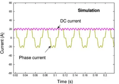
Fig. 11. Phase current in the PMSG and dc current in the battery.
Fig. 12. Phase-to-phase voltage in the PMSG.
IV. EXPERIMENTALVALIDATION OF THEPASSIVEWIND
TURBINESYSTEM
A test bench has been developed in order to experimentally validate the passive wind turbine system (see Fig. 10). It allows a “physical emulation” of the passive wind turbine system, the turbine being “simulated” by a servomotor which reproduces torque and inertia with respect to rotation and wind speeds (
curve). The servomotor is coupled through a torquemeter with the optimal PMSG prototype issued from the IOD ap-proach. The PMSG is itself connected through a three-phase diode rectifier with battery of dc voltage V. The system is controlled by a digital signal processor (DSP) pro-cessor (DS1102 board) which converts sensor information (voltage, current, position, and torque). We investigate the behavior of the passive wind turbine system by comparing ex-perimental measurements with corresponding simulations. For that purpose, a complete three-phase model of the PMSG-diode rectifier and battery association has been developed. This model allows us to characterize phase voltage and phase current in the PMSG and in the diode rectifier as well as the dc voltage and current in the battery. We first compare experiment and
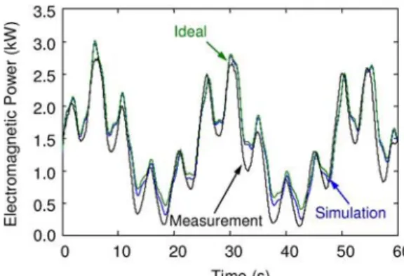
simulation electrical values at the input and output of the diode rectifier for a constant PMSG rotation speed close to the PMSG base speed, i.e., rad.s . Fig. 11 presents the PMSG phase current and dc current. For the same conditions, Fig. 12 gives the phase-to-phase voltage value in the PMSG. In order to validate the passive wind turbine system in wind variable operating, the wind cycle defined by (1) is imposed to the servomotor which emulates the wind turbine. Fig. 13 compares the electromagnetic power and the associated energy during the simulated wind cycle. The maximal power and energy corre-sponding to the case of an ideal wind extraction are also drawn to assess the wind power extraction quality of the passive wind turbine system. Note that differences are not important which confirms the system’s “natural” efficiency when its parameters have been optimized in relation to the wind turbine. Finally, the average useful power during the simulated wind cycle is given in Table IV and compared with average extracted wind power to estimate the global efficiency of the wind turbine system. We also mention in Table IV the average power associated with an ideal wind extraction. It can be seen from measurements that the wind power extraction efficiency related to the particular wind cycle is about 90%. The global efficiency
Fig. 13. Electromagnetic PMSG Power and energy during a wind cycle.
TABLE IV
AVERAGEPOWERS IN THEPASSIVEWINDTURBINESYSTEMDURING AWINDCYCLE
of the wind turbine system is close to 70%. Note also the very good agreement between simulated and experimental results for all investigated tests.
V. CONCLUSION
In this paper, the design of a full passive wind power system based on a 1500-W three-bladed wind turbine has been inves-tigated. Such a “low-cost” structure without active control and with a minimum number of sensors can be efficient only if the system design parameters are mutually adapted through an IOD approach which aims at optimizing the wind power extraction, the total system losses, and the total system mass. Issued from this study, an optimal PMSG prototype has been constructed and implanted in an experimental test bench. This test bench allows a “physical emulation” of the passive wind turbine system, the turbine being “simulated” by a servomotor which reproduces torque and inertia with respect to the rotation and wind speeds. All experimental tests have shown a very good agreement be-tween the system simulations and corresponding measurements. Finally, a good global efficiency of the passive wind turbine system, close to 70%, has been noted from experiments, for the particular wind cycle profile used in the IOD process. All the results obtained in this study confirm the interest of such a “low-cost” passive structure (no control and power electronic devices, a minimum of sensors) sized from an IOD approach. In the outlooks of this work, the sensitivity analysis of the passive wind turbine efficiency according to design variable variations will be investigated in more detail. Robust design methods will be applied in order to take into account design variable uncer-tainties and their impact on design objectives or constraints.
APPENDIX
A. Analytical Models of the PMSG
This Appendix illustrates the calculation of the main electro-magnetic parameters of the PMSG for both analytical models investigated in the paper (see Table V).
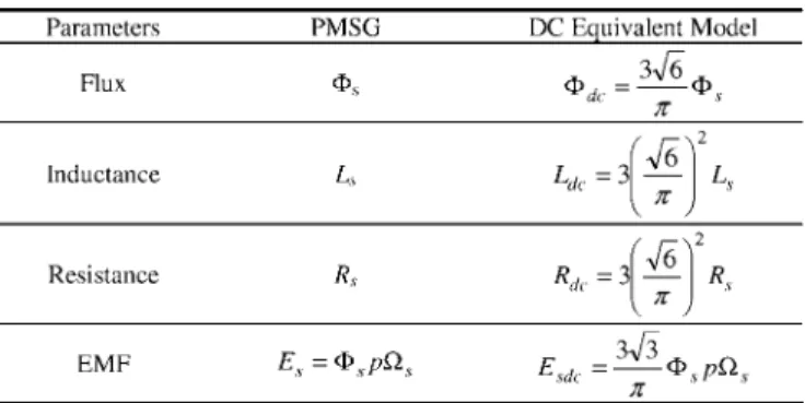
B. DC Equivalent Model
A simplified equivalent dc model is used to represent the behavior of the PMSG-diode rectifier association in transient state [16], [17]. With this model, electrical values are deter-mined from a quasi-static approach using analytical relations. Only thermal and mechanical modes (i.e., slow modes) are sim-ulated by ODE equations. Electrical modes (i.e., fast modes) are neglected. Consequently, the computation time devoted to the simulation of all physical values (thermal, mechanical, and electric values) during a wind cycle is considerably reduced. With this model, the CPU time (on a 2-GHz standard PC com-puter) required for evaluating one individual (including geo-metric sizing, wind simulation, constraint, and objective com-putation) in the NSGA-II is about 0.6 s. This leads to a global CPU time of 10 hours for each NSGA-II run using 100 indi-viduals and 600 generations. More details about the analysis of the CPU time devoted to the electrical simulation of the passive wind turbine can be found in [17].
The correspondence between synchronous generator circuit and the equivalent dc model is given in Table VI. The voltage
can be calculated from Fig. 4 as detailed in [17]
(7) where models the diode overlapping during the commutation interval. From the above relation, we obtain the rectified current
(8) where
(9) (10)
C. Wind Turbine System Parameters
The parameters of the wind turbine and of the optimized PMSG are listed below.
Wind turbine
Radius of wind turbine rotor: m; Equivalent inertia: kg m ;
TABLE V
ELECTROMAGNETICMODELS OFTHEPMSG
TABLE VI
CORRESPONDENCEBETWEENPMSGANDDC EQUIVALENTMODEL
Damping coefficient: N m /rad;
Ideal power coefficients: ;
Interpolation factors of power coefficient:
Mass: kg
PMSG
Base speed: rad s Base Power: W Yoke induction: T Radius/length ratio:
Slot depth/radius ratio:
Current density: A/mm Number of pole pairs: ;
Number of slots per pole per phase: ; Resistance: Ohm; Inductance: mH; Flux: Wb; Active length: mm; Bore radius: mm; Airgap width: mm;
Yoke thickness of stator and rotor: mm; Slot, teeth width: mm;
Active mass: kg;
Diode Rectifier (IXYS- Vue 50)
Radiator mass: kg (issued from optimization) kg (prototype)
Battery
NP38-12 I 12 V 38 Ah.
ACKNOWLEDGMENT
The authors would like to thank the Novelté Système Society for the production of the PMSG prototype.
REFERENCES
[1] J. A. Baroudi, V. Dinavahi, and A. M. Knight, “A review of power converter topologies for wind generators,” Renewable Energy, vol. 32, pp. 2369–2385, 2007.
[2] M. A. M. Prats, J. M. Carrasco, E. Galvan, J. A. Sanchez, L. G. Fran-quelo, and C. Batista, “Improving transition between power optimiza-tion and power limitaoptimiza-tion of variable speed, variable pitch wind tur-bines using fuzzy control techniques,” in 26th Annu. Conf. IEEE
Indus-trial Electronics Society (IECON2000), 2000, vol. 3, pp. 1497–1502.
[3] P. Anandavel, K. Rajambal, and C. Chellamuthu, “Power optimization in a grid-connected wind energy conversion system,” in IEEE Int. Conf.
Power Electronic and Drives Systems, 2005, vol. 2, pp. 1617–1721.
[4] C. Sourkounis and B. Ni, “Optimal control structure to reduce the cu-mulative load in the drive train of wind energy converters,” in 11th Eur.
Conf. Power Electronics and Applications (EPE2005), Dresden, 2005.
[5] C. Sourkounis and B. Ni, “Iterative adapting power control for wind energy converters based on stochastic optimization,” in 9th Int. Conf.
Probabilistic Methods Applied to Power Systems, Stockholm, Sweden,
Jun. 11–15, 2006, Paper KTH.
[6] A. S. Neris, N. A. Vovos, and G. B. Giannakopoulos, “A variable wind energy conversion scheme for connection to weak AC systems,” IEEE
Trans. Energy Convers., vol. 14, no. 1, pp. 122–127, 1999.
[7] A. M. De Broe, S. Drouilhet, and V. Gevorgian, “A peak power tracker for small wind turbines in battery charging applications,” IEEE Trans.
Energy Convers., vol. 14, no. 4, pp. 1630–1635, Dec. 1999.
[8] J. M. Yang, J. Wu, P. Dong, and J. H. Yang, “Passivity-based con-trol in wind turbine for maximal energy capture,” in IEEE Int. Conf.
Electric Utility Deregulation, Restructuring and Power Technologies (DRPT2004), Hong Kong, Apr. 2004.
[9] E. Muljadi, S. Drouilhet, R. Holz, and V. Gevorgian, “‘Analysis of wind power for battery charging,’ Wind Energy Book VIII: Conference Pa-pers,” in Proc. Energy Week ’96, Houston, TX, Jan. 29–Feb. 2 1996, (Incorporating ASME’s Energy-Sources Technology Conf. and Exhi-bition). New York: American Society of Mechanical Engineers; Vol. I: pp. 190-197; NREL Report 21862.
[10] Z. Chen, J. M. Guerrero, and F. Blaabjerg, “A review of the state of the art of power electronics for wind turbines,” IEEE Trans. Power
Elec-tron., vol. 24, no. 8, pp. 1859–1874, Aug. 2009.
[11] K. L. Shi and H. Li, “A novel control of a small wind turbine driven gen-erator based on neural networks,” in Proc. IEEE Power Society General
Meeting, 2004, vol. 2, pp. 1999–2005.
[12] Z. Chen, S. Gomez, and M. Mc Cormic, “A fuzzy logic controlled power electronic system for variable speed wind energy conversion sys-tems,” in Proc. Power Electronic & Variable Speed Drives, 2000, pp. 114–119, Inst. Elect. Eng., Publication 475.
[13] N. Stannard and J. R. Bumby, “Performance aspects of mains con-nected small scale wind turbines,” in IET Generation, Transmission &
Distribution (Formerly Proc. Inst. Elect. Eng.), Mar. 2007, vol. 1, no.
2, pp. 348–356.
[14] S. Jiao, G. Hunter, V. Ramsden, and D. Patterson, “Control system design for a 20 kW wind turbine generator with a boost converter and battery bank load,” in Proc. IEEE PESC Conf., 2001, vol. 4, pp. 2203–2206.
[15] A. Mirecki, X. Roboam, and F. Richardeau, “Architecture cost and en-ergy efficiency of small wind turbines: Which system tradeoff?,” IEEE
Trans. Ind. Electron., vol. 54, no. 1, pp. 660–670, Feb. 2007.
[16] A. Abdelli, B. Sareni, and X. Roboam, “Optimization of a small passive wind turbine generator using multiobjective genetic algorithms,” Proc.
Int. J. Applied Electromagnetics and Mechanics (IJAEM), vol. 26, no.
3–4, pp. 175–182, 2007.
[17] B. Sareni, A. Abdelli, X. Roboam, and D. H. Tran, “Model simplifica-tion and optimizasimplifica-tion of a passive wind turbine generator,” Renewable
Energy, vol. 34, no. 12, pp. 2640–2650, Dec. 2009.
[18] E. Hau, Wind Turbines: Fundamentals, Technologies, Application,
Economics., 2nd ed. New York: Springer-Verlag, 2006.
[19] G. Slemon and X. Liu, “Modeling and design optimisation of perma-nent magnet synschronous motors,” Electric Mach. Power Syst., no. 20, pp. 71–92, 1992.
[20] Z. Q. Zhu, D. Howe, and C. C. Chan, “Improved analytical model for predicting the magnetic field distribution in brushless permanent magnet machines,” IEEE Trans. Magn., vol. 38, no. 1, pp. 229–239, Jan. 2002.
[21] C. Espanet, A. Miraoui, and J.-M. Kauffmann, “Optimal design of an high torque DC brushless in-wheel motor,” in Proc. IEMDC’2003
Conf., Madison, WI, Jun. 2003, pp. 1402–1409.
[22] F. Dubas and C. Espanet, “Exact analytical model of the No-load flux density in the air-gap the permanent magnets and the rotor yoke for the surface mounted permanent magnet motors,” Int. Rev. Elect. Eng., vol. 2, no. 3, pp. 425–437, 2007.
[23] B. Sareni, J. Régnier, and X. Roboam, “Integrated optimal design of heterogeneous electrical energetic systems using multiobjective genetic algorithms,” Int. Rev. Elect. Eng., vol. 1, no. 1, pp. 112–129, 2006.
[24] K. Deb, “Multi objective Optimisation using evolutionary evolutionary algorithms,” in Wiley—Interscience Series in Systems and
Optimiza-tion. Chichester: Wiley, 2001.
[25] B. Sareni, J. Regnier, and X. Roboam, “Recombination and self-adap-tation in multi-objective genetic algorithms,” Lecture Notes in Comput.
Sci., vol. 2936, pp. 115–126, 2004.
[26] X. Roboam, A. Abdelli, and B. Sareni, “Optimization of a passive small wind turbine based on mixed Weibull-turbulence statistics of wind,” in
Proc. Electrimacs 2008, Québec, Canada, 2008.
[27] E. Sambatra, J. Raharijaona, G. Barakat, and B. Dakyo, “Modeling and test of a PM synchronous generator based small stand alone wind en-ergy converter,” in Proc. 12th Int. Power Electronics and Motion
Con-trol Conf. (EPE-PEMC 2006) , 2006, pp. 1591–1596.
[28] D. C. Meeker and E. H. Maslen, “Analysis and control of a three pole radial magnetic bearing,” in Tenth Int. Symp. Magnetic Bearings, Mar-tigny, Switzerland, Aug. 2006.
[29] D. C. Meeker, Finite Element Method Magnetics Sep. 22, 2006, see also, Verison 4.2, User’s Manual, .
Duc-Hoan Tran was born in Nam Dinh, Vietnam, in 1983. He received the M.Sc. degree in electrical engineering from Institut National Polytechnique de Toulouse (INPT), Toulouse, France in June, 2007. He is currently working toward the Ph.D. degree at the Laboratoire Plasma et Conversion d’Energie, Unite Mixte de Recherche, Centre National de la Recherche Scientifique/INPT-UPS.
His research interests include the design of poser systems dedicated to small wind turbines, optimiza-tion algorithms, and other related issues.
Bruno Sareni was born in Bron, France, in 1972. He received the Ph.D. degree in 1999 from the Ecole Centrale de Lyon.
He is currently Associate Professor in Electrical Engineering and Control Systems at the Institut Na-tional Polytechnique of Toulouse, France. He is also Researcher at the Laboratory on Plasma and Conver-sion of Energy (LAPLACE). His research activities are related to the analysis of complex heterogeneous power devices in electrical engineering and the op-timization of these systems using artificial evolution algorithms.
Xavier Roboam (M’96) received the Ph.D. degree in electrical engineering from the Institut National Poly-technique de Toulouse (INPT), Toulouse, France, in 1991.
Since 1992, he has been with the Laboratory of Electrotechnics and Industrial Electronics, Unite Mixte de Recherche, Centre National de la Recherche Scientifique (CNRS)/INPT–Ecole Nationale Supérieure d’Electrotechnique, d’Elec-tronique, d’Informatique, d’Hydraulique et des Télécommunications, Toulouse, France, as a
CNRS Full-Time Researcher. Since 1998, he has been the Head of the team “GENESYS” whose objective is to process design problems at the “system level.” He develops design methodologies specifically oriented toward multi-field systems design for applications such as electrical embedded systems and renewable energy systems.
Christophe Espanet was born in Belfort, France, in 1972. From 1991 to 1995, he studied at the “Ecole Normale Supérieure” in Cachan in Paris, France. He received the Ph.D. degree from the University of Franche-Comté (UFC) in 1999. His doctoral research dealt with the design and the optimization of PM high torque in-wheel motors.
From 1999 to 2007, he has been an Associate Pro-fessor at the Laboratory of Electrical Engineering and Systems (L2ES). He is now Full Professor at the UFC and Head of the Energy Conversion Systems Design Research Team in the FEMTO-ST Laboratory, Belfort, France. His research in-terests include the modeling and the design of electrical systems and more par-ticularly PM synchronous machines.