O
pen
A
rchive
T
OULOUSE
A
rchive
O
uverte (
OATAO
)
OATAO is an open access repository that collects the work of Toulouse researchers and
makes it freely available over the web where possible.
This is an author-deposited version published in :
http://oatao.univ-toulouse.fr/
Eprints ID : 19682
To link to this article :
DOI: 10.1016/j.combustflame.2018.01.007
URL :
http://dx.doi.org/10.1016/j.combustflame.2018.01.007
To cite this version :
Kraus, Christian
and Selle, Laurent
and Poinsot,
Thierry
Coupling heat transfer and large eddy simulation for combustion
instability prediction in a swirl burner. (2018) Combustion and Flame, vol.
191. pp. 239-251. ISSN 0010-2180
Any correspondence concerning this service should be sent to the repository
administrator:
[email protected]
Coupling
heat
transfer
and
large
eddy
simulation
for
combustion
instability
prediction
in
a
swirl
burner
Christian
Kraus
∗,
Laurent
Selle,
Thierry
Poinsot
Institut de Mécanique des Fluides de Toulouse (IMFT), Université de Toulouse, CNRS-INPT-UPS, Toulouse, France
Keywords:
Large eddy simulation Swirl flame Heat transfer Combustion instabilities Coupled simulation
a
b
s
t
r
a
c
t
Largeeddysimulations(LES)ofcombustioninstabilitiesareoftenperformedwithsimplifiedthermalwall boundaryconditions,typicallyadiabaticwalls.However,walltemperaturesdirectlyaffectthegas temper-aturesandthereforethesoundspeedfield.Theyalsocontroltheflameitself,itsstabilization characteris-ticsanditsresponsetoacousticwaves,changingtheflametransferfunctions(FTFs)ofmanycombustion chambers.Thispaperpresentsan exampleofLESofturbulentflamesfullycoupledtoaheat conduc-tionsolverprovidingthetemperatureinthecombustorwalls.LESresultsobtainedwiththefullycoupled approacharecomparedtoexperimentaldata and toLESperformedwithadiabaticwallsforaswirled turbulentmethane/airburnerinstalledatEngler-Bunte-Institute,KarlsruheInstitute ofTechnology and GermanAerospaceCenter(DLR)inStuttgart.Resultsshowthatthefullycoupledapproachprovides rea-sonablewalltemperatureestimationsand thatheatconductioninthecombustorwallsstronglyaffects boththemeanstateandtheunstablemodesofthecombustor.Theunstablethermoacousticmode ob-servedexperimentallyat750Hziscapturedaccuratelybythecoupledsimulationbutnotbytheadiabatic one,suggestingthatcouplingLESwithheatconductionsolverswithincombustorwallsmaybenecessary inotherconfigurationsinordertocaptureflamedynamics.
1. Introduction
Heattransferplaysanimportantroleinmostpower-generating systems usingcombustion,e.g., ingas turbines,aeroengines and rocket engines. The presence of one ormultiple flames leads to high temperaturegradients in thesystem. Depending on the ap-plication,heat transferisconsideredasadesiredoran undesired effect.Inheating unitsitisobviouslynecessaryto fulfillthe pur-pose of the machine. On the contrary, it leads to several design challengesincombustionchambersofgasturbines.Turbineblades andcombustionchamberwallsneedtobecooledinorderto with-stand hot gases. This does not only raise challenges for the de-sign of the solid parts inside the gas turbine, but also for com-putationalfluiddynamics(CFD)whensimulatingthereactiveflow inthecombustion chambers.Boundary conditionshavetobe de-finedinawaythatheattransferprocessesbetweenflowandsolid partsandtheirimpactonthetemperaturefieldinsidethe combus-torareadequatelymodeled, sincethetemperaturedirectlyaffects theflowconditionsandthechemicalreactionsinsidethe combus-tion chamber. AdvancedCFD methods like large eddy simulation (LES)combinedwithsophisticatedflamemodelsordirect
numeri-∗ Corresponding author.
E-mail address: [email protected] (C. Kraus).
calsimulation(DNS)withdetailedchemicalmechanismsonly pro-duce accurateresultswhenthewalltemperaturesinthe combus-tionchamberareknownwithreasonableprecision,whichisrarely thecase.Theproblemalsoappliestothepredictionofcombustion instabilities,astheacousticbehaviorofcombustorcomponentsis determinedbythesoundspeedfieldandthegeometry;flame dy-namicsareusuallyheavilyinfluencedbychangesintemperature.
There are numerousexperimentalandnumericalstudies illus-trating thesignificant influenceofheattransfer onflame dynam-icsandcombustioninstabilities.Duchaineetal.[1]demonstratedin theirsensitivitystudyoftheflametransferfunction(FTF)ofa lam-inar premixedflamethat the duct walltemperaturehas astrong impactonthevelocityfieldandthelocalflamespeed,whichleads to uncertainties in the prediction ofthe phase of the FTF.Kaess etal.[2]investigated theinfluenceofthe thermalwallboundary conditionontheFTFofalaminarpremixedflamewithDNS.Their results showed that the flame anchoring position as well asthe FTFweresignificantlyalteredwhenchangingtheadiabatic bound-aryconditiontoanisothermalboundarycondition.TheFTFofthe casewiththeisothermalwallshowsabetter agreementwiththe experimentally obtainedFTF.Mejiaetal.[3]observedastrong in-fluenceoftheburner rimtemperatureonthecombustion dynam-icsofalaminarpremixedflame: anunstablemodecould be trig-geredbyswitchingonthecoolingsystemoftheburner rim.They
explained this behavior with altered flame foot dynamics [4,5], whichleadinturntochangesintheFTF.ThestudyofHong etal. [6]showedthatheattransferisnotonlycontrolledbytemperature gradients,butalsobythephysicalpropertiesofthesolid combus-torparts.Replacingthestainlesssteelflameholderwithonemade of ceramics inhibited ordelayed the onset of a combustion sta-bility.Theauthorsconcludethatthewallthermalconductivity in-fluences the flamespeed neartheflameholder, whichleads toa distinct dynamicbehavior oftheflameforeachflameholder ma-terial.LohrmannandBüchner[7]investigatedtheinfluenceofthe preheattemperatureontheFTFofaturbulentswirl-stabilized pre-mixedflame.The delayoftheflame responsedecreased with in-creasingpreheattemperature,whichtheyexplainedbyanincrease intheturbulentflamespeedthatshiftsthemainreactionzoneto anupstreamlocation.
Despite the fact that the influence of wall temperatures on flamedynamicshasbeenobservedinmanystudies,amajorhurdle remains:walltemperaturesareverydifficulttodetermineinmost combustors. Asaconsequence,heattransferisneglected inmany CFD simulations. Walls are often treated as adiabatic,or at best isothermalbutwithaguessedtemperature.Nevertheless, numeri-cal simulationsare oftenabletocapturetherightthermoacoustic mode inan unstable laboratory-scalecombustor,even whenheat transfer is neglected. Differences in frequency or amplitude may occur when the temperaturefield and the FTF inthe simulation only partially matchthose inthe experiment, but thesimulation can usually beused forfurther investigationofthe thermoacous-tic mode. There are numerousstudies of combustioninstabilities thatillustratethatLESwithadiabaticwallscanshowareasonable agreement withexperiments:thestudyona lean-premixedswirl combustor by Huang et al. [8], the LES-studies on the PRECCIN-STA configuration[9–11], the massivelyparallel LES of a realistic helicoptercombustionchamber byWolfetal.[12],LESs ofmodel rocketcombustors(Garbyetal.[13],Urbanoetal.[14])orthe LES-studies ofbluff-bodystabilized flamesby Lietal.[15]andGhani etal.[16].
However, as illustrated by the simulation of the LIMOUSINE burnerperformedbyShahietal.[17],takingintoaccounttheheat transfer between theflow and thesolid parts of thecombustion chamber cansignificantlyincreasetheaccuracyoftheresults. An-other exampleisthestudybyKrausetal.[18],whocomparedan adiabaticLESandanLESwithbasicmodelingofheattransfer be-tween fluid and solid material. Both LESs show the same mode structure, buttakinginto account heat transfer effectsleads to a higheraccuracyintermsoffrequency.
Tosummarizethestateoftheartinthisfield,LESof combus-torscanbeclassifiedintofourcategories,dependingontheir ther-malboundaryconditionsonwalls:
• Type1:Adiabaticwalls:themajorityofrecentLESssimply con-siderthewallstobeadiabatic[8–16,19–22].
• Type2:Imposed walltemperatures[23–27]:when experimen-tal data on wall temperatures is available, imposing them as boundaryconditions forLES maybea solution.Notethat this can be a dangerous methodology: imposing a high local wall temperaturemayforexample,forcetheflametoanchoratthis point,diminishingthepredictivequalityofthemethodby forc-ing thesolutionartificially.Moreover,limitedexperimental in-formationisusually availableon walltemperatures,whichare measuredonlyatafewpoints.Theintroductionofdiagnostics such as laser induced phosphorescence [27,28] in laboratory-scale experimentsmayhelp in certain casesasit canprovide a fulltemperaturefieldon combustorwalls.However, inmost real engines, detailed wall temperature information is simply notavailable,makingtype2LESunpracticalinindustrialcases.
• Type3:Asimplemethodtoaccountforwallheattransferisto writeaRobincondition[29]onwallslinkingthewall tempera-tureTwtothelocalheatflux
8
throughaheatresistanceRand acoolingtemperatureT∞:8
=(
Tw−T∞)
/RwhereRisroughly evaluated from the combustor wall characteristics [18,30–32]. This is a cheap methodto account fordual heat transfer be-tweenreactingflowandconductionthroughwalls.• Type 4:Fully coupledLES/heat conductionsolver inthe com-bustor walls: the whole combustor solid structure is also meshedandthetemperaturewithinthesolidstructureis com-putedbyasolvercoupledwiththeLESflowsolver[17,33–35]. Most LES are of type 1 because the combustion community does not consider the problemofheat conduction through walls asan interesting one comparedto the other challenges found in turbulentflames.However,thebenefitsofgoingtoatype4 simu-lationareobviousasshownbyBergeretal.[35]:theLESbecomes fullypredictiveanddoesnotrelyonanyadhocevaluationofwall temperatures in the solid. For a cooled chamber, the only input datais the cooling watertemperature andthe convection coeffi-cientinthecoolingpassagesbetweenwaterandcombustorwalls. On the long term, it is clear that the high precision of LES will requireacorresponding highprecision forwall temperaturesand therefore type 4 simulations. This is true not only for the mean flowcharacteristicsbutalsoforpollutantsandforflamedynamics or flame stabilization: Miguel-Brebion etal. [33],e.g., show that flames stabilizedbehind uncooledorcooled cylindersexhibit to-tallydifferentshapes,whicharewellcapturedwhenatype4 sim-ulation is performed. The results ofthese studies show that not onlyheatlosseshavetobeconsidered,butalsoheattransferinside the solid partsof combustors, asit can havea strong impact on the temperaturefield inside the combustion chamber and there-foreon combustion.Especiallytheadequate modeling ofinternal heat transfer inside the combustor is almost impossible without applying fullycoupled simulations of type 4, since temperatures oninternalwallsincombustorsareinmostcasesunknown.
Thepresentpapershowsthatatype4LESforafullcombustion chamberispossibletodayeveninacomplexswirlburnerandthat itallowssignificant improvementsinthedescriptionoftheflame dynamics,especiallytocaptureself-excitedmodes:takinginto ac-countinternalheattransferfromthecombustionchambertoother combustorpartscanstronglyaffectthermoacousticsandflame dy-namics.
ThecoupledLESisperformedwithafullycompressiblesolver forreactingflows[30,36–38]anda heatconductionsolverin the combustorwallscoupledtotheLESsolverwiththeOpenPalmtool [39](www.cerfacs.fr/globc/PALM-WEB/).Theresultsofthecoupled LESarecomparedtotheresultsofanadiabaticLES,whichis per-formedwiththesamenumericalsetupbutwithadiabaticwalls.
The experimentis briefly presented inSection 2,followed by thedescriptionofthenumericalsetupinSection3.Theimpactof accountingforheattransferinthecoupledsimulationonthe tem-peraturefieldisdepictedinSection4.Meanvelocitiesandacoustic spectraobtainedintheexperimentarecomparedtotheLESdata. Possible reasons for the differences in combustion dynamics ob-servedbetweenadiabaticandcoupledLESarediscussed.Thepaper isconcludedbyasummaryofthemainobservationsandresults.
2. Experimental setup
TheKIT-Burnerisdescribedindetailin[40]and[41],therefore onlyabriefpresentationofitsmainfeaturesisgivenhere.
Identicalversionsofthe burner areinstalled attwo locations: oneatEngler-Bunte-Institute,CombustionTechnologyatKarlsruhe Institute of Technology andthe other atDLR (GermanAerospace Center)in Stuttgart. It is operated under atmospheric conditions
Heating up of
combustion
chamber
Heat
Losses
Heat transfer to
plenum
Measuring point outer
plenum T = 450 K
Measuring point inner
plenum T = 350 K
T = 300 K
Inlet outer plenum
T = 300 K
Inlet inner plenum
Inlet fuel
Outlet
Flame
Fig. 1. KIT-Burner with two separated air inlets for the double-concentric swirl noz- zle. During operation the hot gases in the combustion chamber heat up the com- bustion chamber. Due to heat conduction inside the solid parts heat is transferred to the plenum and heats up the fresh gases.
withnopreheatingofthefreshgases.Asketchofthecombustoris showninFig.1.Itisapproximately1mlongandthecrosssection ofthecombustion chamberis ofrectangularshape,withawidth of89mmandaheightof114mm.Thefirstsection ofthe outlet isofconicalshapeandthesecondsectionhasaconstantdiameter of50mm.Foropticalaccess,thecombustionchamberisequipped withquartz windows.Microphones measure pressure oscillations insidethecombustionchamberandtheplenums.
Thecombustorhastwoairinlets,oneforeachswirler,andthe mass flow in each swirler can be controlled individually. There-fore the nozzle can be operated with different air split ratios
L=m˙OTS/m˙IS (OTS =outer swirler,IS=inner swirler).Perforated platesareinstalledinsideboththeinnerandtheouter plenumto homogenizetheflowbeforeitenterstheswirlers.
Thefueliseithermethane(DLR)ornaturalgas(>90%CH4,KIT) andisinjectedthrough60circumferentiallydistributedholes(hole diameter0.5mm)intotheairflowoftheinnerswirler,which
re-sults inpartiallypremixedflames.The influenceofthefuel com-position onthe amplitudesandfrequencies of theunstable com-bustormodesisverylimited,typically1.5%forthefrequency.
No additional cooling is applied to the combustor, neither to thecombustionchambernortheplenum.Airandfuelareinjected atambienttemperature,i.e. around300K.Atthegivenoperating conditions(thermalpowerPth=30kW,globalequivalenceratio
φ
= 0.85, L = 1.6),the heating-upof thecombustion chamber and the heat transferred into the plenum by heat conduction in the solid materialleadtoflowtemperatures(measuredinthe experi-ment)ofaround450Kintheouterplenumand350Kintheinner plenum.
3. Numerical setup
3.1. Fluidsolver—AVBP
The flow simulations are performed with the solver AVBP, which is developed by CERFACSand IFPEN. AVBP is a finite vol-umesolverwitha cell-vertexapproach [30,37].It solvesthe fully compressible Navier–Stokes equations on unstructured grids. The Lax–Wendroff scheme is used as numerical method, which is of secondorderintimeandspace;theCFL-Numberissetto0.9.The unresolvedturbulentscalesaremodeledwithafiltered Smagorin-skysubgridscalemodel[42].
ReactionkineticsaredescribedwiththeBFERtwo-step mecha-nism formethane[10],whichisvalidoverawiderangeof equiv-alenceratios:
CH4+1.5O2→CO+2H2O,
CO+0.5O2↔CO2.
The dynamic thickened flame model (DTF) [43–47] is used to model turbulence/flame interaction. The DTF model allows to thicken the reaction zones of premixed flames by dividing the chemical pre-exponential constants by a factorF andmultiplying diffusion termsby F.This isdone in alimitedspatial zone iden-tifiedby aflamesensor[44].The flamethicknessbeingincreased byafactorF,anefficiencyfunctionisintroducedtoaccountforthe subgrid scalewrinkling[43,48].
The geometryused in thesimulations comprises the combus-tion chamber and the whole plenum. Ahybrid mesh was gener-ated withthe commercial software CENTAUR, which has around 13.6×10⁶ cells andwas used inboth adiabatic andcoupled LES. One layerofprismcells isusedatthewall (requiredby thewall model[49,50])whileallothercellsaretetrahedral.
TwodifferentLESsarecomparedinthiswork:
-Atype1approachwhereheattransferbetweentheflowand thecombustorpartsiscompletelyneglectedandallwallsare con-sideredasadiabatic.
-Atype4approachwhereheattransferbetweentheflowand the solid combustor parts as well as heat conduction inside the solidpartsaretakenintoaccount.
3.2. SolidheatconductionsolverAVTPandcouplingstrategy
The simulationofheattransferinthesolidcombustorpartsis performedwiththeAVTPcode [51,52],whichsolvesthetime de-pendentenergyequation:
ρ
sCs∂
T∂
t =∂
q˙i∂
xi ,whereTisthetemperature,
ρ
sthedensityandCstheheat capac-ityofthesolidmaterial,whereasq˙idenotesconductionheatflux.AVBP : Inlet
Outer Swirler
AVBP : Inlet
Inner Swirler
AVBP: flow
AVTP: solid
AVBP : Outlet
AVBP :
Fuel Inlet
Fig. 2. Geometries used for the fluid solver AVBP and the solid solver AVTP.
HeatdiffusionismodeledwithFourier’slaw:
˙
qi=−
λ
s∂
T∂
xi,
with
λ
sbeingtheheatconductivityofthesolidmaterial.The dif-ferencesinheatcapacityandheatconductivityofthedifferent ma-terialsusedfortheconstructionofthecombustoraswellasthe in-fluenceoftemperatureonheatcapacityandconductivityaretaken intoaccount.Heattransferviaradiationisnotincludedinthe cur-rentsimulations.The3Dmeshforthesoliddomaincontains4.5×106tetrahedral cells.Thegeometrycomprisesthesolidmaterialofthecombustion chamber andtheplenumaswellaspartsoftheinletsforairand fuel,asdepictedinFig.2.Forspatialdiscretization,asecond-order Galerkin diffusionscheme isapplied and time integrationis per-formedwithanimplicitfirst-orderEulerscheme.
AVBPandAVTParecoupledusingtheOpenPalmsoftware[39]. Thermal equilibrium in the experiment is reached after about 30 min. This is far beyond computational resources for the LES solver(timestep:∼10−7s).Inordertospeedup theconvergence ofthetemperaturefieldinsidethesoliddomain,thefluidandsolid solversarede-synchronizedintime.Thesolidsolveroperateswith larger time steps (∼10−4 s)and during the transientperioddata is exchanged betweenthesolvers every 50iterations of thefluid solver. Thisapproachisequivalenttodecreasingtheheatcapacity ofthe solidmaterial.After thesolid hasreachedthermal equilib-rium,thetimestepofthesolid solverandexchangerateare syn-chronizedwiththetimeadvancementofthefluidsolver.
Comparedtothecomputationallyexpensivefluidsolver,the ad-ditional computational cost dueto thesolid solver is not signifi-cant[53].The increasedcomputational cost ofthecoupled simu-lation ismerely causedbythe additionalsimulationtime needed to reach thermal equilibrium in the solid domain. This leads to a computational cost of around 200000 CPU hours compared to around100000CPUhoursfortheadiabaticsimulationon1056 In-tel 12-CoreE5-2690V3processors (supercomputerOCCIGEN) and 1248 Intel(r) 10 core IVYBRIDGE 2.8 Ghz processors (supercom-puter EOS). It also shows that type 4 LES will become standard inthefuture,sincetheyintroduceacceptableadditionalcost.
f (Hz)
Ph
a
s
e
0
1000
2000
3000
4000
-4.0
-3.5
||
R
||
0.6
0.7
0.9
1.0
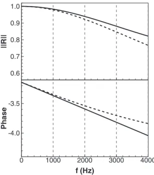
Fig. 3. Modulus and phase of the reflection coefficient R of the combustion cham- ber outlet: impedance model of Levine and Schwinger [57] , NSCBC for- mulation used in the LESs with K = 30 0 0 0 s −1 .
3.3.Boundaryconditions—coupledandadiabaticLES
Theinlet andoutletboundary conditionsinAVBPare handled withtheNSCBCapproach (Navier–Stokes-characteristic-boundary-conditions [54,55]). With the NSCBC approach, the ingoing wave amplitudeL−atthecombustoroutletiswritten:
L−=K(p−p ∞
)
where pis the local pressure, p∞ the pressure at infinity andK therelaxparameteroftheboundarycondition.Themagnitude||R|| andthephase
φ
ofthe NSCBCboundary conditionφ
maybe ex-pressedby[56]:||
R||
=p
1 1+(
2ω K)
2 andφ
=−π
−arctan³
2ω
K´
,withtheangularfrequency
ω
.TherelaxparameterKcanbetuned to match the impedance of the combustion chamber outlet: the acousticbehavioroftheoutletofthecombustionchamberisthat of an open-end pipe, which can be described by the impedance modelbyLevineandSchwinger[57].ThevalueofKoftheNSCBC boundaryconditionatthecombustionchamberoutletintheLESs isadaptedtomatchtheacousticimpedancegivenbythemodelof LevineandSchwinger.WithK=30000s−1,theNSCBCimpedance matchesthemodelimpedanceverywellintherelevantfrequency rangeoff=0–2000Hz(Fig.3).Inordertopredictheattransferbetweenthewallsandthefluid withreasonableaccuracy,thethermalboundarylayerhastobe re-solvedormodeled.Onthewallsoftheoutletsection ofthe com-bustionchamber,no-slipboundaryconditionsareimposedandthe gridresolutionintheregionresultsinvaluesofy+ofaround2–5. Thisalso allows to reproducethe acoustic behavior ofthe outlet section ofthecombustionchamber, which hasastrong influence on the frequency ofthe unstable mode. Wall models [49,50] for momentumandheatare appliedonthe othercombustion cham-berchamber wallsaswell asonthe wallsintheswirlers andin the fuel plenum, as resolving the thermalboundary layer every-whereinthedomainwouldhavebeencomputationallytoocostly. Theflow insidethe airplenumsisconsidered asmostly lami-nar, sincethe Reynoldsnumbersare belowRe = 2000; therefore
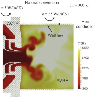
Natural convection
T
= 300 K
h
= 25 W/(m
2K)
AVBP
AVTP
Heat
conduction
h
= 5 W/(m
2K)
Wall law
Fig. 4. Thermal boundary conditions and modeling of heat transfer in the coupled LES. The color field corresponds to an instantaneous field of temperature. (For in- terpretation of the references to colour in this figure legend, the reader is referred to the web version of this article.)
no-slip boundaryconditions are imposed inside the plenum. The heatconductioninsidethesolid materialleadstoaheating upof the perforated plates,which in turnresults in a temperature in-crease ofthe air flow passing through the holes. In orderto ac-count forthis effect, the flow inside the holes of the perforated platesisalsocomputed.
On the coupled boundary surfaces,the heat flux on the wall calculatedbyAVBPisimposedasboundaryconditionforAVTPand thetemperatureatthewallcalculatedbyAVTPisimposedaswall temperature forAVBP. Allwalls in thefluid domain are coupled. Theheat transferontheexternalsurfaceofthewallsofthesolid domain is modeled under the assumption of natural convection, withheattransfercoefficientsofh=5Wm−2K−1fortheplenum wallsandh=25W m−2 K−1 forthecombustionchamber walls, assuming a cooling temperatureof the surrounding airof T∞ = 300K(Fig.4).
4. Results
4.1. Preheatingoffreshgasesduetoheattransferinthecoupled simulation
The preheating of thefresh gasesobserved during the exper-iment can also be observed in the coupled simulation. Figure 5 shows themean temperatures calculatedby thecoupled simula-tionintheflow fieldandthesolid material.Thehot gasesinthe combustion chamber heat the walls ofthe combustion chamber. Thisheat isconductedinsidethesolid materialandheats upthe solid material ofthe plenum. Nearthe inlets ofthe vanes ofthe outer swirler the temperatureof thesolid material rises to tem-peraturesgoingfromT=500to700K.
The hot plenum walls heat the air flows in the plenum: the temperatures of the fresh gasesreach values around T = 360 K in the inner swirler andT = 510 Kin the outer swirler.Heat is alsotransferredtothenozzleandconductedtotheinnerplenum, whichleads toa significantincrease ofthefuelflowtemperature toaroundT=460Kneartheinjectionholes.Table1comparesthe meantemperaturespredictedbytheLESatthelocationswherethe thermocouplesare mountedinthe experiment.The temperatures areverysimilartothosemeasuredintheexperiment,which
indi-Table 1
Air temperatures at measuring points in the plenums in the experiment and the coupled LES.
Case Outer plenum (K) Inner plenum (K)
Experiment 450 350
Coupled LES 443 344
catesthattheheattransferinthesolidmaterialisreasonablywell reproduced.
Figure 6(a) quantifies the heat losses to the surrounding air andtheinternalheattransferinsidethecombustorinthecoupled LESinreferencetoheataddedbythecombustionprocess.Around 10.5%ofthecombustionheatislostattheexternalwalls.Mostof it is transferred by the combustion chamber walls(10%). Around 7% ofthe combustion heat istransferred through the solid parts fromthecombustionchamber totheplenum. Asmallpercentage is lost at theexternal plenum walls(0.5%), butmostof it is ab-sorbedbythefreshgases(6.5%),mostlyintheouterplenum(5%). Heat losses and especially internal heat transfer from the combustion chamber lead to a temperature field in the cou-pled LES which differs significantly from the one in the adia-batic LES. Figure 6(b) shows the relative temperature difference
(
T¯CP− ¯TAD)
/T¯AD on the middle plane of the domain. The highest temperaturesdifferencesarelocatedintheouterplenumnearthe inletsoftheswirlvanesoftheouterswirler(upto140%),whereas the heat lossesinthecombustion chamberresultin temperature decreasesofaround−18%atthecombustionchamberwalls.When thefluid andthesolidsolvers aresynchronizedintime, the temperatures in the solid remain almost constant. This is caused by the disparity of the heat transfer time scale and the characteristicfluidtime scale.Giventhehighheatconductivityof thesolidmaterial,thecorrespondingBiotNumbersBicanbe con-sideredsmall(Bi<0.01).Assumingaconstantfluidtemperature,a characteristictimescalefortheheattransferinthesolidmaterial canbeestimatedwith[58]:
t0=
msCs
hS ,
withthesurfaceareaSandthemassofthesolidms.Dependingon the regionconsidered (stainlesssteelwallsorquartz glasswalls),
t0 variesbetweenvaluesoftheorderof ∼1s to ∼10s. Compar-ing t0 to thecharacteristic time scale of the instability,the time periodT (t0∼10−3 s),itcan bestatedthattransientwallheating does not play an importantrole in thecurrent case. Thereforeit can be assumedthata similartemperaturefield oftheflow field couldhavebeenachievedbyusingisothermalboundaryconditions andimposingtherightwalltemperatures.However,estimatingthe rightwall temperaturesandimposinga similar,complex2D tem-perature distribution,asitisachievedby thecoupledsimulation, isverycomplicated,ifnotimpossibleinthecurrentcase.
The impactofthedifferencesintemperaturebetweencoupled andadiabaticLESonthemeanflowfields,thethermoacoustic be-haviorandtheflamesshapesinbothLESsarediscussedinthe fol-lowingsections.
4.2. Meanflowfields—PIVvs.LES
The PIV measurements were performedby DLR Stuttgart [18]. Figure 7 shows the mean velocity profiles and Fig. 8 the RMS velocities for the axial, radial and azimuthal components at dif-ferent axial coordinates in the combustion chamber. Velocities are normalized by the bulk velocities measured or calculated at the outlets of the swirlers. To calculate the bulk velocity in the experiment,theprofilefortheaxialvelocityisconsideredtobe ax-isymmetric. Table2liststhebulk velocityforeachcase. Thebulk
Heat transfer between hot combustion gases and combustion chamber walls 2200 1700 1200 750 750 750 Combustion chamber Plenum
Heat conduction inside solid material leads to heating up of plenum Quartz windows 600 600 500 400 400 500 600 400 400 400 400 400 400 600 500 500 Combustion chamber Plenum
Hot plenum walls lead to preheating of air and
fuel flows Combustion chamber Plenum 580 580 580 460 460 460 330 330 330 330 460 460
a
b
c
Fig. 5. Preheating of the fresh gases induced by heat transfer between flow and solid material and heat conduction inside the solid domain. (a) Flow temperature in the combustion chamber and near the nozzle outlet, (b) temperature in the solid, (c) flow temperature in the preheating zone.
Combustion
chamber walls
Plenum walls
-0.5 %
Walls inner plenum +1%
0
0
0
-0.175
0
0
0.7
0.7
-0.175
a
b
External
combustion
chamber walls
-10 %
Fluid
Solid
Walls fuel plenum +0.5 %
Walls outer plenum +5%
Plenum
walls
+6.5 %
-7 %
-10 %
Combustion
chamber
dump plane
Q / P
th
.
—
(T
CP
-T
AD
)/(T
AD
)
_
_
_
Fig. 6. (a) Heat losses and internal heat transfer in the coupled LES, the heat fluxes are normalized with the thermal power of the flame ( 1Q/P¯˙ th ), (b) relative mean
temperature difference between the coupled and the adiabatic LES ( ¯T CP − ¯T AD) / ¯T AD on the middle plane of the combustor.
Table 2
Mean bulk velocities in the PIV, the adiabatic and the coupled LES at the nozzle outlet.
Case Bulk velocity ( m s −1 )
Experiment 31.4
Adiabatic LES 23.1
Coupled LES 33.5
velocity in the adiabatic LES is lower than in the experiment, whereas thecoupledLESshowsonlya slightoverestimation.This is clearly due to the preheating of the fresh gasesfound in the experimentandthecoupledLES.Theincreasedfreshgas temper-ature leads toa densitydecrease andtherefore toan increase of thebulkvelocity.
BothLESs show a reasonableagreementwithPIV because ve-locities are only marginally sensitive to temperaturechanges. On
theother hand,whencomparingtheoverallshapeoftheprofiles, discrepancies canbe observedbetweentheadiabaticLESandthe PIV for x/d=0.2 (Fig. 7, left images). PIV and coupled LES ex-hibitmaximummeanaxial velocitiesneartheoutletoftheouter swirler, whereasthey arelocated closertotheburner axisinthe adiabatic LES.In general,theadiabaticLESoverestimatesthe nor-malizedvelocitycomponentsclosetotheburneraxisforx/d=0.2 andx/d=0.4.Thiscanbeexplainedbythepreheatingofthefresh gasesintheexperimentandthecoupledLES,whichcauseshigher temperatures of theair flow inthe outer swirler thanin the in-ner swirler,which in turnleads to higher velocitiesin the outer swirler.SincetheadiabaticLESdoes notaccountforheattransfer processes,itcannotreproducethisbehavior.
Furtherdownstream,themeanflowfieldsoftheLESsaremore similar and show both an overestimation of the angle of the swirl flow. The differences in swirl angle can be caused by the
-1
0
1
-1
0
1
x/d = 1.2
D
is
ta
n
c
e
to
a
x
is
r
/d
-1
0
1
1.5
1
0.5
0
0.5
1
1.5
x/d = 0.2
-1
0
1
x/d = 0.4
-1
0
1
-1
0
1
D
is
ta
n
c
e
to
a
x
is
r
/d
-1
0
1
1.5
1
0.5
0
0.5
1
1.5
-1
0
1
-1
0
1
-1
0
1
Radial velocity/Bulk velocity
Tangential velocity/Bulk velocity
-1
0
1
x/d = 1.6
D
is
ta
n
c
e
t
o
a
x
is
r
/d
-1
0
1
1.5
1
0.5
0
0.5
1
1.5
Axial velocity/Bulk velocity
Fig. 7. Mean normalized velocities in the PIV ( ), the adiabatic LES ( ) and the coupled LES ( ).
significantly higher velocity fluctuations in the LESs (Fig. 8), as amplitudeandfrequencyofvelocity oscillationscaninfluencethe mean flow field in a swirlflow [59–61]. The increased RMS ve-locities inbothLESare relatedtothepressurespectra,whichare furtherdiscussedinSection4.3.
4.3. Pressurespectra
As discussed inSection4.2,both LESs showreasonable agree-ment with theexperiment regardingthe meanflow fields.
How-ever,thisisnot thecasefortheacoustics andtheunstablemode (Fig.9).Thepressurespectrainthecombustionchamberillustrate that both LESs show a combustion instability, but the frequency oftheunstablemodeinthe adiabaticLES(f= 864Hz)is signifi-cantlyhigherthanintheexperiment(f=750Hz)andthemode amplitudeissignificantlylower.ThefrequencyinthecoupledLES agreesperfectlywiththe experiment(f=750Hz) andthemode amplitudeinthecombustionchamberiscomparabletotheonein theexperiment. The frequencyresolution ofthe pressure spectra oftheLESisabout
1
f=8Hz.D
is
ta
n
c
e
t
o
a
x
is
r
/d
0
1
1.5
1
0.5
0
0.5
1
1.5
0
1
0
1
0
1
x/d = 1.6
0
1
x/d = 1.2
0
1
0
1
0
1
0
1
RMS Axial velocity/Bulk velocity
Radial velocity/Bulk velocity
0
1
x/d = 0.4
Tangential velocity/Bulk velocity
D
is
ta
n
c
e
to
a
x
is
r
/d
0
1
1.5
1
0.5
0
0.5
1
1.5
D
is
ta
n
c
e
to
a
x
is
r
/d
0
1
1.5
1
0.5
0
0.5
1
1.5
x/d = 0.2
Fig. 8. Mean normalized RMS of the velocities in the PIV ( ), the adiabatic LES ( ) and the coupled LES ( ).
Differences betweenthe spectra of both LESs and the exper-iment are found in the low-frequency range, especially the in-ner plenumatfrequencies around f=500Hz.Thisindicates that the acoustic impedances of the inner plenum are not perfectly reproduced in the simulations. Possible reasons for this are the walls, which are perfectly reflective in the LESs, which is not thecaseintheexperiment;additionalsourcesofuncertaintiesare theimpedances ofthe perforatedplatesinthe LESs.Eventhough the flow in the holes is calculated, small differencesin the hole geometries betweentheexperiment andtheLES, duetoe.g., the
manufacturingprocessoftheholes,mayaffecttheholeimpedance [62,63] andleadtodiscrepancies betweensimulationand experi-ment. Themeshresolutioninandaroundthe holesmayalsonot be sufficient to perfectly reproduce the acoustic behavior of the perforatedplatesintheLESs.
Although the difference in accuracy regarding the simulation of the instability between the coupled and the adiabatic LES is very significant, it should be noted that the results of the LESs are alsoinfluenced by other factors (chemistry model,numerical accuracy, subgrid models, boundary conditions). It is therefore
f (Hz)
p
’
RMS(Pa
)
200 400 600 800 1000 1200 0 200 400 600 800 1000Combustion
chamber
f (Hz)
p
’
RMS(Pa
)
200 400 600 800 1000 1200 0 20 40 60 80 100Inner Plenum
f (Hz)
p
’
RMS(Pa
)
200 400 600 800 1000 1200 0 20 40 60 80 100 120Outer Plenum
Combustion chamber Outer plenum Inner plenumFig. 9. Pressure spectra in the PIV ( ), the adiabatic LES ( ) and the coupled LES ( ).
possible that choosing a different chemical mechanism [64], increasing the mesh resolution, applying a different model for the turbulent flame [65,66] orusing different acoustic boundary conditionswouldhavean impactontheflow fieldandtheflame structureandinfluenceacousticspectraandcombustiondynamics. Accounting forheat radiation could alsoinfluence amplitudeand frequencyoftheunstablemodeintheLES.Bergeretal.[35]show thatradiativefluxescanbeofthesameorderofmagnitudeasthe convective fluxes. However, they also observed that accounting for heat radiation had only a limited impact on the flow. While investigating the sensitivity of the LESs to different numerical models representsan significant topic, it is beyondthe scope of this work. In any case, the present results strongly suggest that takingintoaccountheattransferwithinthecombustorwallshasa strong impacton thethermoacousticmodesinthe combustor.In ordertofurtherinvestigatewhythisisthecase,themodeshapes of theunstable modes, theflame shapesandthe distributions of the mean Rayleigh indexin both LES cases are discussed in the followingsection.
4.4. Unstablemodestructures,flameshapesandRayleighindex
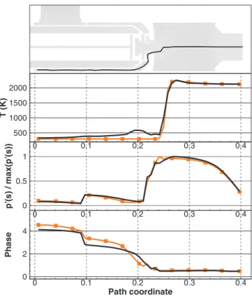
In order to compare the mode shapes of the main unstable modes in both LEScases, the valuesof the meanamplitude and phase ofthepressureoscillationsinthecombustionchamber,the outer swirler and the outer plenum were extracted following a predefinedpath.Figure 10showsthepathwherepressure ampli-tude andphasewere extractedandcomparesthe resultingmode structures in theadiabatic andthecoupledLES. Themode shape inthecombustionchamberdoesnotshowasignificantgradientin the transversedirection:therefore,forclarityreasons,itwasonly extracted on the centerline.The modesshapesare similar;
how-Path coordinate Ph a s e 0 0.1 0.2 0.3 0.4 0 2 4 p ’(s ) / m a x (p ’(s )) 0 0.1 0.2 0.3 0.4 0 0.5 1 T (K ) 0 0.1 0.2 0.3 0.4 500 1000 1500 2000
Fig. 10. Mode structures of the unstable modes in the adiabatic LES ( ) and the coupled LES ( ). The mode structures were extracted along the path depicted in the upper image.
Heat Release
Rate (W/m
3)
1e+08 3e+08 1e+08 3e+08 3e+08 3e+08Maximum heat release rate in the adiabatic case 4.4e+08 W/m3
4.4e+08
Adiabatic
Coupled
Maximum heat release rate in the coupled case 5.0e+08 W/m3
4.4e+08
Adiabatic
Coupled
Coupled
Adiabatic
0.00
-0.20
0.15
0.30
0.00
-0.65
0.50
1.00
0 0 0 0 0 0 0 0 0 0 0 0 0 0 0Normalized
Rayleigh Index
a
b
d
c
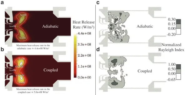
Fig. 11. Mean fields of heat release rate (a, b) and Rayleigh index (c, d) in the adiabatic (a, c) and the coupled LES (b, d).
ever,differencesonbothamplitudeandphasearefoundinsidethe outer swirlerandtheouter plenumnearthe inletsoftheswirler vanes.Thisindicatesthat thetemperatureincrease intheplenum induces changes in theacoustic impedance, whichin turnsleads todifferencesinthemodeshapecomparedtotheadiabaticLES.
Figure 11showsmeanfieldsofheat releaserateandRayleigh indexesinbothLESs,normalizedbythemaximumvaluefoundin bothLES.TheRayleighindex(RI)isdefinedas:
RI= 1
τ
Z
τ p′q˙′dt,
wherep′andq˙′arerespectivelythepressureandheatreleaserate
fluctuationsand
τ
isthetime periodofthemode.Itcharacterizes the interactionof theflame withthe acousticfield:a positive RI means that the flame adds energyto the acoustic field, whereas an RI smaller than zeromeans that unsteadycombustion damps acoustic oscillationsin theseregions. Thepreheating ofthefresh gasesandthesubsequentincreasedflamespeedinthecoupledLES hasseveraleffects:comparedtotheadiabaticcase,themaximum heat releaseis increasedandthe flame ismore compact and lo-catedfurtherupstream.ThedistributionsoftheRayleighindexare also different:in thecoupled case, theregions with positiveand negativeRIsareclearlyseparatedandthehighestRIs arefoundin theregionwiththehighestheatreleaserate.Intheadiabaticcase, thezonesofnegativeandpositiveRIsareratherdistributed.Consistentobservations aremade analyzingtheaxial distribu-tion ofthemean heatreleaserateandthe RI.The mainreaction zone is more compact in the coupled case and the flame is lo-cated furtherupstream (Fig.12). Inboth LESs the meanheat re-lease rate continuously grows and diminishes, with a maximum valueataroundx/d=0.9inthecoupledLESandaroundx/d=1.0 in theadiabatic LES.In thecoupled LES,the axial distributionof theRIfollowstheshapeofthemeanheatreleaseratewithasmall shiftintheupstream directionandreachesitsmaximumvalueat around x/d=0.8.Thisisnot thecaseintheadiabatic LES,where theaxialdistributionoftheRIexhibitsadifferentshapethanthe heat releasedistribution andreachesits maximumfurther down-stream.
The fieldsoftheRIrepresent allthermoacousticmodesinthe combustor andnot only themain unstable mode. Aseparate as-sessmentoftheRIforeachmodeisnotavailablewithourcurrent database. However,itisclearlyvisiblethatthecharacteristicsand the locationsofthe strongestthermoacoustic couplingare
differ-x/d
0 1 2 3 4 0.0 0.2 0.4 0.6 0.8 1.0Fig. 12. Mean axial distributions of: the heat release rate in the adiabatic LES ( ) and the coupled LES ( ), the RI in the adiabatic LES ( ) and the coupled LES ( ).
ent inbothcases.Since thedistributionofthe RIisnot available intheexperimentaldata,itcannotbesaidtowhatextentthe cou-pledLESmatchesthethermoacousticsoftheexperiment.However, the fact thatthe verygood agreementinterms offrequencyand amplitudestronglysuggeststhatthecoupledLESreproduces well thecombustioninstabilityintheexperiment,whichillustratesthe advantages of coupledsimulations comparedto adiabatic simula-tions whenheat transfer has a significant impacton combustion dynamics.
5. Conclusions
The current paper discusses the potential of fully coupled LES/heat transfer simulation to improve the accuracy of numer-ical simulations for the prediction of combustion instabilities. The combustion instability in a laboratory-scale swirl burner is
computed with an adiabatic and a fully coupled LES, which ac-countsforheattransfer betweenflow andburner aswellasheat conduction in the solid burner structure.The resultsof the LESs and their comparison with the experimental data show that al-though thecoupledsimulation doesnot significantlyimprovethe predictionofthemeanvelocity field,itperforms muchbetter re-garding the prediction of frequencyand amplitudeof the unsta-blemode.Theheatconductioninsidethesolidstructureresultsin a preheatingof the fresh gasesin the coupled LES, which influ-ences themodeshapeandaltersthecharacteristicsofthe flame-acousticscouplingincomparisonoftheadiabaticLES.
The results stronglysuggest that, in order to obtain an accu-ratepredictionofcombustioninstabilities,itmaybemandatoryto account forheat transfer in the solid structure incombustors of complexgeometry,whereheattransferhasastrongimpactonthe flowtemperature. Coupledsimulationsprovideanexcellent possi-bilitytodothis,asthefull3Ddistributioninthesolidmaterialcan becomputed,andthecouplingofthefluidandthesolidsolver al-lows toimpose a non-uniform,complex 2D temperaturefield on thewallboundariesforthefluidsolver,whichisimpossibleto ob-tainwithnon-coupledsimulations.
Acknowledgments
Theresearchleadingtotheseresultshasreceivedfundingfrom the European Research Council under the European Union’s Sev-enthFrameworkProgramme(FP/2007-2013)/ERCGrantAgreement ERC-AdG319067-INTECOCIS.
Thisworkwasgrantedaccesstothehigh-performance comput-ingresourcesofCINESundertheallocationx20162b_7036madeby GrandEquipementNationaldeCalculIntensif.
ThesupportofCalmipforaccesstothecomputationalresources ofEOSisacknowledged.
The authorswould like to express their gratitude to CERFACS andFlorentDuchaineforprovidingthecoupledAVBP/AVTPsolver. TheauthorswouldalsoliketothanktheDeutsche Forschungs-gemeinschaft, which supported the research leading to the ex-perimental results through the funding of the Collaborative Re-search Center606(SFB606).Theauthorsthankthe Engler-Bunte-Institute,CombustionTechnologyatKITandtheGermanAerospace CenterinStuttgartforprovidingtheexperimentaldata.
References
[1] F. Duchaine, F. Boudy, D. Durox, T. Poinsot, Sensitivity analysis of transfer func- tions of laminar flames, Combust. Flame 158 (12) (2011) 2384–2394, doi: 10. 1016/j.combustflame.2011.05.013 .
[2] R. Kaess , W. Polifke , T. Poinsot , N. Noiray , D. Durox , T. Schuller , S. Can- del , CFD-based mapping of the thermo-acoustic stability of a laminar premix burner, Proceedings of the 2008 Summer Program (2008), pp. 289–302 . [3] D. Mejia, L. Selle, R. Bazile, T. Poinsot, Wall-temperature effects on flame re-
sponse to acoustic oscillations, Proc. Combust. Inst. 35 (3) (2014) 3201–3208, doi: 10.1016/j.proci.2014.07.015 .
[4] K.S. Kedia, H.M. Altay, A.F. Ghoniem, Impact of flame-wall interaction on pre- mixed flame dynamics and transfer function characteristics, Proc. Combust. Inst. 33 (1) (2011) 1113–1120, doi: 10.1016/j.proci.2010.06.132 .
[5] A. Cuquel, D. Durox, T. Schuller, Impact of flame base dynamics on the non- linear frequency response of conical flames, C.R. Mec. 341 (1–2) (2013) 171– 180, doi: 10.1016/j.crme.2012.11.004 .
[6] S. Hong, S.J. Shanbhogue, K.S. Kedia, A.F. Ghoniem, Impact of the flame-holder heat-transfer characteristics on the onset of combustion instability, Combust. Sci. Technol. 185 (10) (2013) 1541–1567, doi: 10.1080/00102202.2013.816575 . [7] M. Lohrmann, H. Büchner, Prediction of stability limits for LP and LPP gas tur-
bine combustors, Combust. Sci. Technol. 177 (12) (2005) 2243–2273, doi: 10. 1080/00102200500241040 .
[8] Y. Huang, H.-G. Sung, S.-Y. Hsieh, V. Yang, Large-Eddy simulation of combustion dynamics of lean-premixed swirl-stabilized combustor, J. Propul. Power 19 (5) (2003) 782–794, doi: 10.2514/2.6194 .
[9] S. Roux, G. Lartigue, T. Poinsot, U. Meier, C. Bérat, Studies of mean and un- steady flow in a swirled combustor using experiments, acoustic analysis, and large Eddy simulations, Combust. Flame 141 (1–2) (2005) 40–54, doi: 10.1016/ j.combustflame.20 04.12.0 07 .
[10] B. Franzelli, E. Riber, L.Y. Gicquel, T. Poinsot, Large Eddy simulation of combus- tion instabilities in a lean partially premixed swirled flame, Combust. Flame 159 (2) (2012) 621–637, doi: 10.1016/j.combustflame.2011.08.004 .
[11] P.S. Volpiani, T. Schmitt, D. Veynante, Large eddy simulation of a turbulent swirling premixed flame coupling the TFLES model with a dynamic wrinkling formulation, Combust. Flame 180 (2017) 124–135, doi: 10.1016/j.combustflame. 2017.02.028 .
[12] P. Wolf, G. Staffelbach, L.Y. Gicquel, J.-D. Müller, T. Poinsot, Acoustic and large eddy simulation studies of azimuthal modes in annular combustion chambers, Combust. Flame 159 (11) (2012) 3398–3413, doi: 10.1016/j.combustflame.2012. 06.016 .
[13] R. Garby, L. Selle, T. Poinsot, Large-Eddy simulation of combustion instabilities in a variable-length combustor, C.R. Mec. 341 (1–2) (2013) 220–229, doi: 10. 1016/j.crme.2012.10.020 .
[14] A. Urbano, L. Selle, G. Staffelbach, B. Cuenot, T. Schmitt, S. Ducruix, S. Candel, Exploration of combustion instability triggering using large eddy simulation of a multiple injector liquid rocket engine, Combust. Flame 169 (2016) 129–140, doi: 10.1016/j.combustflame.2016.03.020 .
[15] H.-G. Li, P. Khare, H.-G. Sung, V. Yang, A large-eddy-simulation study of com- bustion dynamics of bluff-body stabilized flames, Combust. Sci. Technol. 188 (6) (2016) 924–952, doi: 10.1080/00102202.2015.1136296 .
[16] A. Ghani, T. Poinsot, L. Gicquel, G. Staffelbach, LES of longitudinal and trans- verse self-excited combustion instabilities in a bluff-body stabilized turbulent premixed flame, Combust. Flame 162 (11) (2015) 4075–4083, doi: 10.1016/j. combustflame.2015.08.024 .
[17] M. Shahi, J.B. Kok, J. Roman Casado, A.K. Pozarlik, Transient heat transfer be- tween a turbulent lean partially premixed flame in limit cycle oscillation and the walls of a can type combustor, Appl. Therm. Eng. 81 (2015) 128–139, doi: 10.1016/j.applthermaleng.2015.01.060 .
[18] C. Kraus, L. Selle, T. Poinsot, C.M. Arndt, H. Bockhorn, Influence of heat transfer and material temperature on combustion instabilities in a swirl burner, J. Eng. Gas Turbines Power (2016), doi: 10.1115/GT2016-56368 .
[19] Y.C. See, M. Ihme, Large eddy simulation of a partially-premixed gas turbine model combustor, Proc. Combust. Inst. 35 (2) (2015) 1225–1234, doi: 10.1016/j. proci.2014.08.006 .
[20] V. Moureau, P. Domingo, L. Vervisch, From large-eddy simulation to di- rect numerical simulation of a lean premixed swirl flame: filtered laminar flame-PDF modeling, Combust. Flame 158 (7) (2011) 1340–1357, doi: 10.1016/ j.combustflame.2010.12.004 .
[21] R. Mercier, V. Moureau, D. Veynante, B. Fiorina, LES of turbulent combustion: on the consistency between flame and flow filter scales, Proc. Combust. Inst. 35 (2) (2015) 1359–1366, doi: 10.1016/j.proci.2014.05.149 .
[22] G. Bulat, E. Fedina, C. Fureby, W. Meier, U. Stopper, Reacting flow in an in- dustrial gas turbine combustor: LES and experimental analysis, Proc. Combust. Inst. 35 (3) (2015) 3175–3183, doi: 10.1016/j.proci.2014.05.015 .
[23] S.R. Gubba, S.S. Ibrahim, W. Malalasekera, A.R. Masri, Measurements and LES calculations of turbulent premixed flame propagation past repeated obstacles, Combust. Flame 158 (12) (2011) 2465–2481, doi: 10.1016/j.combustflame.2011. 05.008 .
[24] P. Palies, T. Schuller, D. Durox, L.Y.M. Gicquel, S. Candel, Acoustically perturbed turbulent premixed swirling flames, Phys. Fluids 23 (3) (2011) 037101, doi: 10. 1063/1.3553276 .
[25] H.J. Krediet, C.H. Beck, W. Krebs, S. Schimek, C.O. Paschereit, J.B.W. Kok, Iden- tification of the flame describing function of a premixed swirl flame from LES, Combust. Sci. Technol. 184 (7–8) (2012) 888–900, doi: 10.1080/00102202.2012. 663981 .
[26] S. Gövert, D. Mira, J.B. Kok, M. Vázquez, G. Houzeaux, Turbulent combustion modelling of a confined premixed jet flame including heat loss effects using tabulated chemistry, Appl. Energy 156 (2015) 804–815, doi: 10.1016/j.apenergy. 2015.06.031 .
[27] R. Mercier, T.F. Guiberti, A. Chatelier, D. Durox, O. Gicquel, N. Darabiha, T. Schuller, B. Fiorina, Experimental and numerical investigation of the influ- ence of thermal boundary conditions on premixed swirling flame stabilization, Combust. Flame 171 (2016) 42–58, doi: 10.1016/j.combustflame.2016.05.006 . [28] J. Brübach, C. Pflitsch, A. Dreizler, B. Atakan, On surface temperature measure-
ments with thermographic phosphors: a review, Prog. Energy Combust. Sci. 39 (1) (2013) 37–60, doi: 10.1016/j.pecs.2012.06.001 .
[29] K. Gustafson , Domain decomposition, operator trigonometry, robin condition, in: J. Mandel, F. Charbel, X.C. Cai (Eds.), Proceedings of the 10th International Conference on Domain Decomposition Methods, vol. 218, American Mathemat- ical Society, Boulder (1998), pp. 432–437 .
[30] P. Schmitt, T. Poinsot, B. Schuermans, K.P. Geigle, Large-eddy simulation and experimental study of heat transfer, nitric oxide emissions and combustion in- stability in a swirled turbulent high-pressure burner, J. Fluid Mech. 570 (May) (2007) 17, doi: 10.1017/S0 0221120 060 03156 .
[31] I. Hernández, G. Staffelbach, T. Poinsot, J.C. Román Casado, J.B. Kok, LES and acoustic analysis of thermo-acoustic instabilities in a partially premixed model combustor, C.R. Mec. 341 (1–2) (2013) 121–130, doi: 10.1016/j.crme.2012.11.003 . [32] M. Bauerheim, G. Staffelbach, N.A. Worth, J.R. Dawson, L.Y.M. Gicquel, T. Poinsot, Sensitivity of LES-based harmonic flame response model for tur- bulent swirled flames and impact on the stability of azimuthal modes, Proc. Combust. Inst. 35 (3) (2015) 3355–3363, doi: 10.1016/j.proci.2014.07.021 . [33] M. Miguel-Brebion, D. Mejia, P. Xavier, F. Duchaine, B. Bedat, L. Selle, T. Poinsot,
Joint experimental and numerical study of the influence of flame holder tem- perature on the stabilization of a laminar methane flame on a cylinder, Com- bust. Flame 172 (2016) 153–161, doi: 10.1016/j.combustflame.2016.06.025 .
[34] A. Ghani , M. Miguel-Brebion , L. Selle , F. Duchaine , D.T. Poinsot , Effect of wall heat transfer on screech in a turbulent premixed combustor, Center for Turbu- lence Research Proceedings of the Summer Program (2016), pp. 133–141 . [35] S. Berger, S. Richard, F. Duchaine, G. Staffelbach, L.Y.M. Gicquel, On the sen-
sitivity of a helicopter combustor wall temperature to convective and radia- tive thermal loads, Appl. Therm. Eng. 103 (2016) 1450–1459, doi: 10.1016/j. applthermaleng.2016.04.054 .
[36] N. Gourdain, L. Gicquel, G. Staffelbach, O. Vermorel, F. Duchaine, J.-F. Boussuge, T. Poinsot, High performance parallel computing of flows in complex geome- tries: II. Applications, Comput. Sci. Discovery 2 (1) (2009) 015004, doi: 10.1088/ 1749-4699/2/1/015004 .
[37] O. Colin, M. Rudgyard, Development of high-order Taylor–Galerkin schemes for LES, J. Comput. Phys. 162 (2) (20 0 0) 338–371, doi: 10.10 06/jcph.20 0 0.6538 . [38] T. Schönfeld , M. Rudgyard , Steady and unsteady flows simulations using the
hybrid flow solver AVBP, AIAA J. 37 (11) (1999) 1378–1385 .
[39] F. Duchaine, S. Jauré, D. Poitou, E. Quémerais, Analysis of high performance conjugate heat transfer with the OpenPALM coupler, Comput. Sci. Discovery 8 (1) (2015) 15003, doi: 10.1088/1749-4699/8/1/015003 .
[40] C. Kraus, S. Harth, H. Bockhorn, Experimental investigation of combustion instabilities in lean swirl-stabilized partially-premixed flames in single- and multiple-burner setup, Int. J. Spray Combust. Dyn. 0 (0) (2016) 1–23, doi: 10. 1177/1756827715627064 .
[41] C.M. Arndt, M. Severin, C. Dem, M. Stöhr, A.M. Steinberg, W. Meier, Experimen- tal analysis of thermo-acoustic instabilities in a generic gas turbine combustor by phase-correlated PIV, chemiluminescence, and laser Raman scattering mea- surements, Exp. Fluids 56 (4) (2015) 1–23, doi: 10.10 07/s0 0348- 015- 1929- 3 . [42] F. Ducros, P. Comte, M. Lesieur, Large-eddy simulation of transition to turbu-
lence in a boundary layer developing spatially over a flat plate, J. Fluid Mech. 326 (1996) 1–36, doi: 10.1017/S0 0221120960 08221 .
[43] O. Colin, F. Ducros, D. Veynante, T. Poinsot, A thickened flame model for large eddy simulations of turbulent premixed combustion, Phys. Fluids 12 (7) (20 0 0) 1843–1863, doi: 10.1063/1.870436 .
[44] J.P. Legier , T. Poinsot , D. Veynante , Dynamically thickened flame LES model for premixed and non-premixed turbulent combustion, Proceedings of the Sum- mer Program (20 0 0), pp. 157–168 .
[45] C. Martin, L. Benoit, F. Nicoud, T. Poinsot, Y. Sommerer, Large-Eddy simulation and acoustic analysis of a swirled staged turbulent combustor, AIAA J. 44 (4) (2006) 741–750, doi: 10.2514/1.14689 .
[46] M. Boileau, G. Staffelbach, B. Cuenot, T. Poinsot, C. Berat, LES of an ignition sequence in a gas turbine engine, Combust. Flame 154 (1–2) (2008) 2–22, doi: 10.1016/j.combustflame.20 08.02.0 06 .
[47] P. Schmitt, T. Poinsot, B. Schuermans, K.P. Geigle, Large-Eddy simulation and experimental study of heat transfer, nitric oxide emissions and combustion in- stability in a swirled turbulent high-pressure burner, J. Fluid Mech. 570 (2007) 17, doi: 10.1017/S0 0221120 060 03156 .
[48] F.L. Sacomano Filho, G. Kuenne, M. Chrigui, A. Sadiki, J. Janicka, A consistent artificially thickened flame approach for spray combustion using LES and the FGM chemistry reduction method: validation in Lean Partially Pre-vaporized flames, Combust. Flame 184 (2017) 68–89, doi: 10.1016/j.combustflame.2017.05. 031 .
[49] O. Cabrit, F. Nicoud, Direct simulations for wall modeling of multicomponent reacting compressible turbulent flows, Phys. Fluids 21 (5) (2009) 1–59, doi: 10. 1063/1.3123528 .
[50] F. Jaegle, O. Cabrit, S. Mendez, T. Poinsot, Implementation methods of wall functions in cell-vertex numerical solvers, Flow Turbul. Combust. 85 (2) (2010) 245–272, doi: 10.1007/s10494-010-9276-1 .
[51] F. Duchaine, S. Mendez, F. Nicoud, A. Corpron, V. Moureau, T. Poinsot, Conju- gate heat transfer with large eddy simulation for gas turbine components, C.R. Mec. 337 (6–7) (2009a) 550–561, doi: 10.1016/j.crme.20 09.06.0 05 .
[52] F. Duchaine, A. Corpron, L. Pons, V. Moureau, F. Nicoud, T. Poinsot, Develop- ment and assessment of a coupled strategy for conjugate heat transfer with large eddy simulation: application to a cooled turbine blade, Int. J. Heat Fluid Flow 30 (6) (2009b) 1129–1141, doi: 10.1016/j.ijheatfluidflow.20 09.07.0 04 . [53] S. Jaure, F. Duchaine, G. Staffelbach, L.Y.M. Gicquel, Massively parallel conjugate
heat transfer methods relying on large eddy simulation applied to an aero- nautical combustor, Comput. Sci. Discovery 6 (1) (2013) 015008, doi: 10.1088/ 1749-4699/6/1/015008 .
[54] T.J. Poinsot, S. Lele, Boundary conditions for direct simulations of compress- ible viscous flows, J. Comput. Phys. 101 (1) (1992) 104–129, doi: 10.1016/ 0 021-9991(92)90 046-2 .
[55] V. Granet, O. Vermorel, T. Léonard, L. Gicquel, T. Poinsot, Comparison of non- reflecting outlet boundary conditions for compressible solvers on unstructured grids, AIAA J. 48 (10) (2010) 2348–2364, doi: 10.2514/1.J050391 .
[56] L. Selle, F. Nicoud, T. Poinsot, Actual impedance of nonreflecting boundary con- ditions: implications for computation of resonators, AIAA J. 42 (5) (2004) 958– 964, doi: 10.2514/1.1883 .
[57] H. Levine, J. Schwinger, On the radiation of sound from an unflanged circular pipe, Phys. Rev. 73 (4) (1948) 383–406, doi: 10.1103/PhysRev.73.383 .
[58] T.L. Bergman , A.S. Lavine , F.P. Incropera , D.P. Dewitt , Fundamentals of heat and mass transfer, 7th ed., John Wiley & Sons, Inc., 2011 .
[59] U. Idahosa, S. Basu, A. Miglani, System level analysis of acoustically forced nonpremixed swirling flames, J. Therm. Sci. Eng. Appl. 6 (3) (2014) 031015, doi: 10.1115/1.4027297 .
[60] S.V. Alekseenko , V.M. Dulin , Y.S. Kozorezov , D.M. Markovich , Comparison of ax- ial forcing effect on a strongly swirling jet and lifted propane-air flame, Pro- ceedings of the 23th International Colloquium on the Dynamics of Explosion and Reactive Systems (2011), p. 361 .
[61] J. O’Connor, T. Lieuwen, Recirculation zone dynamics of a transversely excited swirl flow and flame, Phys. Fluids 24 (7) (2012), doi: 10.1063/1.4731300 . [62] M.A. Temiz , J. Tournadre , I.L. Arteaga , P. Martínez , Effect of orifice geometry on
the non-linear acoustic resistance of perforated plates in the transition regime, The 22nd International Conference on Sound and Vibration: ICSV 22, 12–16 July 2015, Florence, Italy (2015a), pp. 1–8 .
[63] M.A. Temiz , I. Lopez Arteaga , A. Hirschberg , Sound absorption measurements for micro-perforated plates : the effect of edge profile, Euronoise 2015, the 10th European Congress and Exposition on Noise Control Engineering, Euro- pean Acoustics Association, Maastricht, The Netherlands (2015b), pp. 1–5 . [64] A. Felden , L. Esclapez , A. Misdariis , E. Riber , H. Wang , Including real fuel chem-
istry in large-eddy simulations, 7th European Conference for Aeronautics and Aerospace Sciences (EUCASS), Milan, Italy (2017) .
[65] D. Veynante, V. Moureau, Analysis of dynamic models for large eddy simu- lations of turbulent premixed combustion, Combust. Flame 162 (12) (2015) 4622–4642, doi: 10.1016/j.combustflame.2015.09.020 .
[66] P. Wang, J. Fröhlich, U. Maas, Z. Xia He, C. Jun Wang, A detailed comparison of two sub-grid scale combustion models via large eddy simulation of the PREC- CINSTA gas turbine model combustor, Combust. Flame 164 (2016) (2016) 329– 345, doi: 10.1016/j.combustflame.2015.11.031 .