HAL Id: hal-02355184
https://hal.archives-ouvertes.fr/hal-02355184
Submitted on 13 Nov 2019
HAL is a multi-disciplinary open access
archive for the deposit and dissemination of sci-entific research documents, whether they are pub-lished or not. The documents may come from teaching and research institutions in France or abroad, or from public or private research centers.
L’archive ouverte pluridisciplinaire HAL, est destinée au dépôt et à la diffusion de documents scientifiques de niveau recherche, publiés ou non, émanant des établissements d’enseignement et de recherche français ou étrangers, des laboratoires publics ou privés.
Some guidelines for the kinematic design of new
manipulators
Philippe Wenger
To cite this version:
Philippe Wenger. Some guidelines for the kinematic design of new manipulators. Mechanism and Machine Theory, Elsevier, 2000, 35 (3), pp.437-449. �10.1016/S0094-114X(99)00015-4�. �hal-02355184�
Some guidelines for the kinematic design of new
manipulators
Philippe Wenger
Institut de Recherche en Cyberne'tique de Nantes, u.m.r. C.N.R.S. no. 6597 1 rue de la Noe , BP 92101, 44321, Nantes Cedex France
Abstract
This work provides tools and guidelines for the designer of new manipulators in order that, in the synthesis process, there can be the possibility to adjust the kinematic parameters in function of three unusual but important kinematic properties (1) cuspidality (non-singular posture changing ability), (2) genericity (stability of the kinematic properties with respect to small variations in the design parameters) and (3) solvability (the inverse kinematic problem can be solved with quadratics). This work should contribute to the use of alternative manipulator designs. © 1999 Elsevier Science Ltd. All rights reserved.
1. Introduction
Most industrial manipulators are solvable, i.e. their inverse kinematic problem reduces to the solution of quadratic equations. Solvability based design results in manipulators with severe simplifying geometric conditions like parallel and intersecting joint axes and reduces considerably the possibility to design manipulators with new interesting properties. However, the increasing progress in the computation of non-closed form inverse kinematic solutions has enabled the use of alternative manipulator designs. An unusual important kinematic feature may arise in manipulators with non-standard geometries, namely, the non-singular posture changing ability. A manipulator is said to change posture, when it goes from one inverse kinematic solution to another [1]. A change of posture may be desired for various purposes, like joint limit or obstacle avoidance. Non-redundant manipulators, which are the subject of
this work, are commonly said to have to cross a singularity when changing posture. lf this statement is true for most current industrial manipulators [1], it is now established that the non-singular posture changing ability may occur in many non-redundant manipulators structures [2-5]. Such manipulators are called cuspidal manipulators, because of the existence of cusp points (i.e. points with three coincident inverse kinematic solutions) in their workspace [6]. The possibility for a manipulator to change posture without meeting a singularity can be considered as an enhancement of manipulator performances. However, there is no definite statement as to whether a cuspidal manipulator is a better design than a non-cuspidal one. To answer this difficult question, one should consider other kinematic features, like solvability [7] or genericity [8], which are intimately related to the non-singular posture changing ability (see Section 4.3). Anyway, the non-singular posture changing ability may strongly affect manipulator control and trajectory planning. Anyone involving in the control of a new manipulator should be aware of the possible existence of several inverse kinematic solutions which are not separated by a singularity. But more importantly, it is of primary importance for the designer of a new manipulator to have the possibility to 'tune' the design parameters in function of the desired posture changing property. However, there is no tool available for helping the designer in such a task. The synthesis of new manipulators generally relies on the optimization of various geometric/kinematic criteria like global workspace requirements (e.g., shape, volume and density, connectivity) or local performances (e.g., dexterity), but, as far as we know, the non-singular posture changing property has never been taken into account in the design process. The aim of this work is to provide tools for the purpose of new manipulator design, in order that it is possible to adjust the kinematic parameters according to whether a cuspidal manipulator is desired or not. Relationship with genericity and solvability is also studied. The analysis presented here applies to non-redundant 3R positioning manipulators and 6R spatial manipulators with spherical wrist.
This article is organized as follows. Section 2 recalls the cuspidality property. Section 3 derives DH-parameter based conditions for cuspidal manipulators. The application of these conditions to the design of new manipulators is treated in Section 4, where the relationship between cuspidality, genericity and solvability is also studied. Section 5 concludes this work.
2. Cuspidal manipulators
A cuspidal manipulator is one which can change posture without meeting a singularity. The existence of manipulators having this property was first pointed out in [2,3]. A theory was developed in [4] for the characterization of new uniqueness domains in the joint space of cuspidal manipulators. ln [5], the non-singular changing posture mechanism was deeply analyzed using typical examples. lt was shown, in particular, that if a manipulator can change posture without passing through a singularity, it cannot do so in all parts of its workspace, but only in a region with four inverse kinematic solutions. A major difficulty has been the characterization of cuspidal manipulators. lt has been conjectured by different authors that (1) manipulators with geometric simplifying conditions like intersecting, orthogonal or parallel joint axes are not able to avoid a singularity when changing posture, and, conversely, (2) manipulators with arbitrary kinematic parameters have the non-singular posture changing
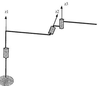
property. These conjectures were based on the observation of several examples which tend to follow this rule. Unfortunately, the examination of counter-examples have clearly revealed that the aforementioned conjectures could not be stated in such a general way. ln effect, the manipulator depicted in Fig. 1 (with conventional DH-parameters α1 = -80°, α2 = 70°,
a1 = 2.5, a2 = 0.5, a3 = 2, d2 = 1, d3 = 0.3), can be shown to be non-cuspidal [9]. On the
other hand, Fig. 2 shows a cuspidal manipulator with several simplifying geometric conditions. A significant progress in the characterization of cuspidal manipulators was done in [6]. lt was shown that a 3-DOF positioning manipulator can execute a non-singular change of posture if and only if there exists at least one point in its workspace with exactly three coincident inverse kinematic solutions. ln a cross section of the workspace, such points are defined as cusp points (hence the word 'cuspidal' manipulators). Fig. 2 depicts a cuspidal manipulator along with the generator of its workspace (i.e. a half cross-section) with four cusp points (the DH-parameters for this manipulator are α1 = -90°, α2 = 90°, a1 = 1, a2 = 2, a3 = 1.5, d2 = 1, d3 = 0). Note that this manipulator has several simplifying kinematic conditions. The cusp points are located at the corner points of a four-solutions region. A cusp point appears when two singular segments bounding the four-solutions region, merge tangentially. Each segment is characterized by a pair of coincident inverse kinematic solutions, and only one solution is common to two adjacent segments. The remaining distinct solutions coincide at the cusp points, resulting in three equal solutions.
More details regarding properties of cusp points can be found in [5,10]. Note that the two points located on the joint axis 1 are not cusp points, since they appear at the corners of a two-solutions region of the workspace (see Fig. 3).
The equivalence between the existence of cusp points and the ability to change posture without meeting a singularity provides a useful tool for the purpose of manipulator design.
Fig. 2. Cusp points in a cross section of the workspace for a cuspidal manipulator.
Section 3 is devoted to the investigation of DH-parameters based cuspidality rules for the design of new manipulators.
3. DH-parameters based conditions
3.1. Effects of simplifying geometric conditions
Most industrial manipulators have simple kinematic parameters, and it turns out that they are non-cuspidal. The first common feature of most industrial 6-DOF manipulators is the
presence of a spherical wrist, i.e. the last three joint intersect at a common point. ln this way, the manipulator can be decomposed into a positioning (or regional) structure (the first three links), and an orienting device (the wrist). This work will deal with positioning 3R manipulators. Since a 6-DOF manipulator with a spherical wrist can be shown to be cuspidal if and only if its positioning structure is cuspidal [4], the results presented in this study can be extended to any 6R manipulator with wrist.
Manipulator singularities generate surfaces that divide the joint space into two or more singularity-free domains, called c-sheet [3] or aspect [1]. For a manipulator to be cuspidal, more than one inverse kinematic solution must exist in a same c-sheet. Thus, a manipulator which admits only two inverse kinematic solutions is non-cuspidal (since in this case there is only one solution in each c-sheet [2]). On the other hand, for a manipulator with four inverse kinematic solutions to be non-cuspidal, its joint space must have at least four c-sheets, i.e., the singularities must divide the joint space into at least four singularity-free domains. lt is worth noting that this last condition is not sufficient. A manipulator with four or more c-sheets may be still cuspidal (see Fig. 3).
When the determinant of the Jacobian can be put in a factored form (which arises under simplifying geometric conditions), there are more than two singularity surfaces in the joint space, yielding more than two c-sheets. We will study the influence of geometric simplifications on the possibility to execute non-singular posture changing trajectories. The basic simplifying conditions to be analyzed are those which may simplify the kinematic equations, i.e. nullify DH-parameters
1. two parallel joint axes, i.e. sin(αi) = 0
2. two intersecting joint axes, i.e. ai = 0 3. two orthogonal joint axes, i.e. cos(αi ) = 0
4. joint offset vanishes, i.e. di = 0
lt is not sure that the aforementioned simplifying conditions necessarily lead to non-cuspidal manipulators (in Fig. 2 the manipulator has orthogonal joint axes and last joint offset vanished, but is still cuspidal). The seek for non-cuspidal geometries is carried out by first exhibiting all geometric simplifying conditions which lead to manipulators with at least four c- sheets. Then, we have to verify that there is only one inverse kinematic solution per c-sheet. To perform this task, it is sufficient to check for an arbitrary point in each region with four solutions in the workspace [10]. Finally, six conditions, referred to as NC1 to NC6, have been found which lead to non-cuspidal manipulators
(NC1) first two joint axes are parallel (i.e. sin(α1) = 0) (NC2) last two joint axes are parallel (i.e. sin(α2) = 0) (NC3) first two joint axes intersect (e.g. a1 = 0) (NC4) last two joint axes intersect (e.g. a2 = 0)
(NC5) first two joint axes are orthogonal, and no joint offset (i.e. cos(α1) = 0, d2 = 0 and
d3 = 0)
(NC6) first two joint axes and last two joint axes are orthogonal and first joint offset vanishes (cos(α1) = 0, cos(α2) = 0, d2 = 0)
• The conditions NC1 to NC6 were found to be also solvability conditions in [7] and non-genericity conditions in [8]. Relation between cuspidality, solvability and non-genericity will be discussed in Section 4.2.
• The preceding list endows the classical industrial manipulator classes (e.g. Puma), but also unusual structures.
• The existence of two parallel (resp. two intersecting) joint axes always leads to non-cuspidal manipulators.
• On the other hand, the simultaneous existence of two pairs of orthogonal joint axes (cos(α1) = cos(α2) = 0) is not sufficient for defining a non-cuspidal manipulator.
• When, in addition to the simultaneous existence of two pairs of orthogonal joint axes, the last joint offset vanishes (d3 = 0), the manipulator is still cuspidal. However, when the first joint offset vanishes (d2 = 0), the manipulator turns non-cuspidal (from NC6).
The conditions NC1 to NC6 provide interesting and simple rules for the designer of a new manipulator. ln some cases, however, it may be not desirable to apply the aforementioned simplifying conditions (e.g. due to other design constraints). ln fact, it turns out that other geometric conditions (not necessarily simplifying) exist which also lead to non-cuspidal manipulators. This point will be discussed in Section 3.2.
3.2. Manipulators with orthogonal joint axes
Consider the family of positioning 3R manipulators such that cos(α1) = cos(α2) = 0. The determinant of the Jacobian can be written as
det(J) = (c2(a2 + a3c3) + d3s2)(a2s3 - d2c3) + a1s3(a2 + a3c3) (1)
where ci, si stand for cos(θi ), sin(θi ), respectively.
lf no other DH-parameters vanishes, det(J) cannot be factored. lf, in addition to cos(α1) = cos(α2) = 0, we set d3 = 0 (like for the robot depicted in Fig. 1), det(J) can be put in the following factored form
det(J) = (a2 + a3c3)((a2s3 - d2c3)c2 + a1s3) (2)
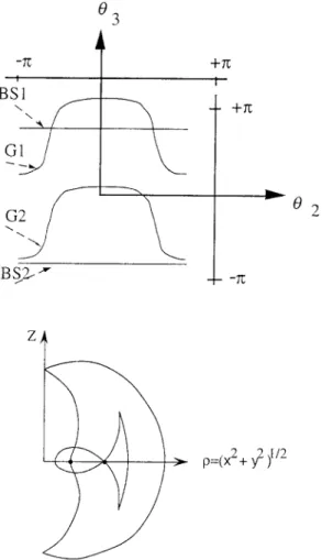
The right-hand side factor yields two general singularities G1 and G2 in the joint space. When la3l < la2l, the first factor is always different from zero. When la3l>la2l, the first factor can vanish and there are two additional branch singularities BS1 and BS2 in the joint space (see Fig. 3, since the singularities are always independent from 81, they can be represented in (α2, α3)).
The general singularities G1 and G2 (resp. BS1 and BS2) are the configurations for which the end-effector lies on a line which passes through all joint axes (resp. reaches the last joint axis z3).
When there is no intersection between the BSi's and the Gi's, the manipulator belongs to a class of generic manipulators, which were shown in [11] to be non-cuspidal. On the other hand, it can be shown that the manipulator becomes cuspidal whenever one BSi intersects one Gi [9] (like in Fig. 3). lt is apparent from the right-hand side factor of Eq. (2) that the general singularities G1 and G2 do not depend on a3. When a3 varies, the additional branch
• = ( + ( ) )
Fig. 3. Singularities in the joint space (a) and workspace half cross-section (b) when la3l > la2l (DH-parameters
a1 = d2 = 1, a2 = 2 and a3 = 2.5).
singularities BS1 and BS2 'move', while G1 and G2 remain unchanged. Thus, it is easy to derive geometrically the condition under which no intersection occurs, which, in turn, is a condition for the manipulator to be non-cuspidal. lt was shown in [9] that this condition can be expressed as 2 2 2 2 3 2 (1 ( ) ) 1 2 d a a a a > + − (3)
Thus, we can write a new DH-parameter based condition, NC7, for a manipulator to be non- cuspidal cos(α1) = 0 cos(α2) = 0 d3 = 0 2 2 2 2 3 2 (1 ( ) ) 1 2 d a a a a > + −
Note that the inequality condition (3) is not intuitive and has no simple physical meaning. ln summary, a 3R manipulator with orthogonal joint axes (cos(α1) = cos(α2) = 0) is non- cuspidal if the remaining DH-parameters satisfy one of the following conditions
• a1 = 0 (from NC3) • a2 = 0 (from NC4) • d2 = 0 (from NC6)
d3 0 and a32 > a22 1 d2 2
4 11
When none of the preceding conditions is satisfied, a manipulator with orthogonal joint axes can be still non-cuspidal under special values of its ai and di. However, although no analytical condition has been found, numerical investigations have shown that the set of (ai,di ) which lead to non-cuspidal geometries with four solutions appears to be drastically reduced [10].
3.3. General case
Consider now general 3R manipulators. We will attempt to derive a general analytical condition for a 3R manipulator to be cuspidal (or non-cuspidal). This would permit to enumerate all possible non-cuspidal manipulator geometries. To reach this goal, we have to derive the existence condition of a cusp point. First, we have to write the equation, in the workspace, of the singular manifolds with three equal roots. There are several ways to do this. We can derive discriminant based conditions from the inverse kinematic polynomial. We can alternatively use a more compact technique as in [10,11]. lt is shown that the points with three equal roots can be defined by the following equations
M4 = M ‘ = M’’ = 0 (4)
4 4
where M4 is the zero-order coefficient of the inverse kinematic polynomial in tan(θ1/2), and M ‘
(resp. M4 ) is the first (resp. second) partial derivative of M4 with respect to θ1. Note that M4 depends on the DH-parameters, and on the Cartesian position (X, Y, Z ) of the end-effector. lt is worth noting that Eq. (4) includes points with more than three equal roots (which are not cusp points). Since we are interested here in points with exactly three equal roots, the condition
M4‘’’ ≠ 0 should be added to Eq. (4), where M4‘’’ is the third derivative of M4 with respect to θ1. This additional constraint eliminates points with four equal roots (appearing in non-generic cases when two singularities intersect in the joint space) as well as points with an infinity of inverse kinematic solutions (occurring when the end-effector lies on a joint axis). Thus, the cusp points can be calculated by
M4 = M ‘ = M’’ = 0 and M ‘’’ ≠ 0 (5)
4
The partial derivatives of M4 with respect to 81 are obtained by noticing that, X ‘ = -Y, Y ‘ =
X and Z ‘ = 0 (since X and Y can be put in the form X = cos(θ1)F(θ2,θ3) and
Y = sin(θ1)G(θ2,θ3), respectively).
By expressing for a general robot, the coefficient M4 and its derivatives, Eq. (5) can be put in the following form
2 2 2
(R + U) +K(N + Y) -(a2a3) = 0
V(R + U) + KX(N + Y) = 0
V 2 - U(R + U) + K(Y 2 - Y 2 - NY) = 0
V(4U + R) + K(4XY + NX) ≠ 0 (6)
where
K = a2sin(α1)2/sin(α2)2
N = (cos(α2)d3 + d2 - cos(α1)Z)/sin(α1)
R = d2 N sin(α1) +( X 2 + Y 2 + Z 2 + a12 )/2 – (a22 + a32 + d22 + d32 + 2d2 d3 cos(α2))/2
U = d2 sin(α1)Y - a1 X
V = d2 sin(α1)X + a1 Y
with the assumption that sin(α1) ≠ 0 and sin(α2) ≠0 (otherwise NC1 or NC1 is satisfied and the manipulator is always non-cuspidal). Note that N depends on Z, U and V depend on X and Y, and R depend on X, Y and Z.
Our aim is to find condition on the DH-parameters. Thus, we need to eliminate the Cartesian coordinates between the first three equations in (6). We use MAPLE to solve Eq. (6). lt is found that the 'simplest' way is to eliminate successively Z and X in the first three equations of (6). The resulting equation is of the form Y 16P(Y ), where P(Y ) is a polynomial
of degree 32 in Y and whose coefficients are extremely complex expressions of the DH- parameters (each coefficient contains more than thousand terms of degree 12 in the DH- parameters). We can verify that the trivial solution Y = 0 yields X = 0, i.e. points lying on the first joint axis, which are not cusps, since at such points, the inverse kinematic problem admits an infinity of solutions. Thus, P(Y ) must have at least one real root for a cusp point to exist. ln the general case, P(Y ) cannot be factored, and no analytical existence condition can be derived. When cos(α1) = 0, P(Y ) can be shown to take a simpler factored form ((Y - cos(α2)d3 - d2)/sin(α2))8Q(Y ) , where Q is a polynomial of degree 6 in Y. lt is easy to
show that the solution Y = (cos(α2)d3 + d2)/sin(α2) is a spurious one. Thus, for a cusp point to exist, it is necessary that the polynomial Q(Y ) have at least one real solution. Unfortunately, Q
cannot be further factored under the only condition cos(α1) = 0, and no symbolic cusp point existence condition can be derived. The additional condition cos(α2) = 0 does not simplify the expression of Q. An alternative way of deriving the equations of the cusp points using the conic method [7] has been attempted, but the resulting equations are similar to Eq. (6). For generic manipulators, Ref. [10] shows that the cusp points can also be characterized using the determinant of the Jacobian. Unfortunately, the resulting equations, again, leads to unwieldy expressions. The problem of deriving a general DH-parameter based condition for a manipulator to be cuspidal appears to be untractable.
4. Cuspidality and the design of new manipulators
4.1. Integration of the cuspidality condition into an optimization scheme
The design of a new manipulator is generally carried out through the optimization of a set of relevant criteria. However, the singular/non-singular posture changing feature is never considered in the optimization process. ln order to take into account this important feature, the conditions for the existence of cusp points can be checked numerically by using (6), which can be integrated as constraints in the optimization process.
Assume that a cuspidal design is desired. ln this case, the verification procedure which has to be considered at each step of the optimization process can be set as follows
If any of the NCi, i = 1,. . . , 4 is satisfied (which are the simplifying geometric conditions for
non-cuspidality) then Reject else If (3) is satisfied then Reject else
If (6) has no real solution then Reject
else Accept
Conversely, when a non-cuspidal manipulator is desired, the preceding procedure, with the inversions of the words 'reject' and 'accept', should be applied.
The seek for real solutions to Eq. (6) is not a major task, and can be achieved using numerical techniques.
4.2. Genericity, solvability, and cuspidality
The interesting concept of generic manipulators was first studied by Paï [8], and later by Burdick [12]. A manipulator is said generic if its singularities are generic, that is, if they form
smooth manifolds in the joint space. Practically, for a manipulator to be generic, its singular surfaces should not intersect in the joint space. Paï showed that the set of non-generic manipulators is codimension one (e.g., forms an hyper surface) in the space of all manipulators. That is, a manipulator is almost always generic, in the sense that if the geometric parameters of a manipulator are given at random, the probability to get a non- generic manipulator is null. An important feature of generic manipulators is that their global kinematic properties remain stable under small changes in their kinematic parameters. This is not true for non-generic manipulators, which turn generic under infinitely small variations in the value of their design variables. This means that particular attention must be paid when manufacturing a non-generic manipulator, since too large manufacturing tolerances may profoundly modify the expected kinematic properties of the manipulator (see Ref. [11] for more details). A list of non-generic manipulators was provided in [8], and it turns out that most industrial manipulators are, in theory, non-generic.
Solvable manipulators were introduced as those for which the inverse kinematic problem reduces to the solution of quadratic equations. Solvability was investigated for 3R manipulators in [7]. As already mentioned, the conditions NC1 to NC4 appear to be also solvability conditions. Thus, any manipulator satisfying one of the NCi's is non-cuspidal, non- generic and solvable, which is the case for most industrial manipulators. Furthermore, it is easy to show that any solvable manipulator is necessarily non-cuspidal. ln effect, the degree of the inverse kinematic polynomial is 2 for solvable manipulators. Thus, we cannot have points with exactly three equal roots (points with four equal roots may exist but are not cusps). Since a solvable manipulator is necessarily non-cuspidal, the inverse kinematic problem of a cuspidal manipulator requires the resolution of a quartic polynomial.
Solvable manipulators with four solutions were shown in [7] to be always non-generic. On the other hand, a non-generic manipulator is not necessarily non-cuspidal (see condition (2) in Section 3.2).
Finally, most generic manipulators with four solutions are cuspidal. ln effect, generic manipulators with four solutions were shown in [11] to be classified into eight distinct classes of homotopic manipulators (i.e. manipulators with similar global kinematic properties). lt turns out that all classes but one are subsets of cuspidal manipulators. Furthermore, the only class of non-cuspidal manipulators was shown to be very 'thin' in comparison with the other seven classes.
The scheme in Fig. 4 summarizes the classification of 3R regional manipulators. The set of 3R manipulators with four solutions, M, is represented as a two-dimensional set for more legibility. The set of non-generic geometries divides M into the aforementioned eight homotopic classes of generic manipulators. lt appears that M is composed of mainly generic cuspidal manipulators. The investigation of the set of 3R manipulators with only two inverse kinematic solutions has not yet been addressed, and its classification is not included in Fig. 4.
4.3. Comments
Solvable manipulators are 'nice' since their inverse kinematics is simple. Generic manipulators are also interesting for stability reasons (see Section 4.2). However, a 3R manipulator cannot be solvable and generic in the same time. The non-singular posture
Fig. 4. Classification of the set of 3R manipulators with four solutions (scheme).
changing ability is also an interesting feature in itself. Most cuspidal manipulators are generic, but, unfortunately, no cuspidal manipulator is solvable. Manipulators have often joint limitations, which reduce their joint space. A cuspidal manipulator with joint limits may not have the possibility to change posture without meeting a singularity. When the checking procedure in Section 4.1 concludes that a manipulator is cuspidal, the cusp point found with Eq. (6) may not exist in the actual workspace. The corresponding triple inverse kinematic solution should be calculated in order to see whether it is within the joint limits of the manipulator at hand.
Manipulators with prismatic joints have not been analyzed here. lt can be easily shown that 3-DOF manipulators with at least two prismatic joints are always non-cuspidal, because they are solvable. Those with one prismatic joint may be cuspidal. The checking procedure described in Section 4.1 can be also applied to such manipulators (with the exception of PRR manipulators for which the inverse kinematic polynomial should be derived in d1, and the derivatives of M4 should be calculated with respect to d1).
5. Conclusions
This article shows how it is possible to take into account, in the design stage, the possibility for a manipulator to execute non-singular changing posture motions. Some geometric simplifying conditions which lead to non-cuspidal manipulators have been provided. Non- cuspidal 3R manipulators with orthogonal joint axes have been more deeply analyzed. A general checking procedure has been derived on the basis of the existence condition of cusp points in the workspace. The connections between the concepts of solvability, genericity and cuspidality have been studied. The results presented here apply to 3R manipulators and 6R
manipulators with spherical wrist. Generalization to manipulators with prismatic joints is straightforward. Spatial manipulators with non-spherical wrist are under study. First results show that the simplifying geometric conditions NC1 to NC4 are not sufficient when applied to general 6R manipulators.
References
[1] P. Borrel, A. Liegeois, in Proc. lEEE lnt. Conf. Rob. and Aut., 1986, pp. 1180-1185. [2] C.V. Parenti, C. lnnocenti, in Proc. 7th ClSM-lFTOMM Romansy '88, 1988, pp. 400-407. [3] J. Burdick, Ph.D. Dissertation, Stanford, 1988.
[4] P. Wenger, in Proc. lEEE lnt. Conf. on Rob. and Aut., 1992, pp. 442-447.
[5] P. Wenger, J. El Omri, in Proc. lEEE lnt. Conf. on Rob. and Aut., 1996, pp. 3173-3178. [6] P. Wenger, J. El Omri, in Proc. 7th lnt. Conf. on Advanced Robotics, 1995.
[7] D.R. Smith, Ph.D. Dissertation, Georgia lnstitute of Technology, Atlanta, 1990. [8] D.K. Pai" , in Proc. lEEE lnt. Conf. on Rob. and Aut., 1989, pp. 738-744. [9] J. El Omri, Doctoral Dissertation, Ecole Centrale de Nantes, 1996. [10] K.Y. Tsai, Ph.D. Dissertation, University of Wisconsi, 1990.
[11] P. Wenger, J. El Omri, in Proc. Advances in Robot Kinematics, 1996, pp. 109-118. [12] J.W. Burdick, Mech. Mach. Theory 30 (1995) 71-89.