HAL Id: hal-01863256
https://hal.archives-ouvertes.fr/hal-01863256
Submitted on 28 Aug 2018HAL is a multi-disciplinary open access archive for the deposit and dissemination of sci-entific research documents, whether they are pub-lished or not. The documents may come from teaching and research institutions in France or abroad, or from public or private research centers.
L’archive ouverte pluridisciplinaire HAL, est destinée au dépôt et à la diffusion de documents scientifiques de niveau recherche, publiés ou non, émanant des établissements d’enseignement et de recherche français ou étrangers, des laboratoires publics ou privés.
Mechanical behavior of as-fabricated Zircaloy-4
claddings under the simulated thermo-mechanical
post-DNB conditions of a Reactivity Initiated Accident
(RIA)
Thomas Jailin, Nicolas Tardif, Jean Desquines, Michel Coret, Marie-Christine
Baietto, Thierry Breville, Philippe Chaudet, Vincent Georgenthum
To cite this version:
Thomas Jailin, Nicolas Tardif, Jean Desquines, Michel Coret, Marie-Christine Baietto, et al.. Mechan-ical behavior of as-fabricated Zircaloy-4 claddings under the simulated thermo-mechanMechan-ical post-DNB conditions of a Reactivity Initiated Accident (RIA). Top Fuel 2018, Sep 2018, Prague, Czech Republic. �hal-01863256�
MECHANICAL BEHAVIOR OF AS-FABRICATED ZIRCALOY-4
CLADDINGS UNDER THE SIMULATED THERMO-MECHANICAL
POST-DNB CONDITIONS OF A REACTIVITY INITIATED ACCIDENT (RIA)
T. JAILIN
1,2, N. TARDIF
2, J. DESQUINES
1, M. CORET
3, M.-C BAIETTO
2, T.
BREVILLE
4, P. CHAUDET
2, V. GEORGENTHUM
11 Institut de Radioprotection et de Sûreté Nucléaire (IRSN), PSN-RES, Cadarache, Saint Paul lez Durance, 13115, France
2 Université de Lyon, CNRS, INSA-LYON, LaMCoS (UMR 5259), Villeurbanne, France 3 GeM (UMR 6183), École Centrale de Nantes, Nantes, France
4 ATYS Consulting Group, Herbeys, France
ABSTRACT
The present work aims at characterizing the thermal-mechanical behavior of as-fabricated Stress Relieved Annealed (SRA) Zircaloy-4 claddings under simulated loading conditions of a Reactivity Initiated Accident (RIA), just after Departure from Nucleate Boiling (DNB). An experimental device was setup in order to simulate post-DNB conditions on fuel rods samples. Ballooning creep tests were performed in inert environment (argon) at internal pressure ranging from 1 to 50 bar. A thermal loading was applied by induction heating. First, the sample was heated at 1000°C/s. The temperature was then stabilized at the test set point until the burst of the specimen.
Typical investigated temperatures ranged from 800°C to 1100°C in the two-phase domain. Thermal and 3D-kinematics fields were recorded during the whole experiment using high-speed cameras. The present paper shows the results of two tests highlighting a strong impact of the thermal transient.
1.
Introduction
A Reactivity Initiated Accident (RIA) is one of the design basis accidents studied for Pressurized Water Reactors (PWR). It might result from unexpected ejection of a control rod out of the nuclear core. The accident can be split up in two steps: the Pellet Clad Mechanical Interaction (PCMI) and then the post-Departure from Nucleate Boiling (post-DNB). During the post-DNB phase, the cladding heating rate can exceed 1000°C/s up to temperatures higher than 900°C. During this step, the release of fissions gas induces a pressure-controlled loading within the cladding. Internal pressure of several tens of bar is expected, inducing ballooning and finally potential cladding burst. The present work aims at characterizing the thermal-mechanical behavior of as received Zircaloy-4 fuel rods under simulated post-DNB loading conditions.
In post-DNB conditions, the cladding temperature can reach the allotropic phase transformation (hcp => bcc) occurring above 820°C under equilibrium conditions for as-fabricated Stress Relieved Annealed (SRA) Zircaloy-4. It is well known that the phase transformation is highly dependent of the thermal history ([1], [2]). Due to the difficulty of reproducing well-controlled fast thermal transients, experimental data do not investigate heating rates above 200°C/s ([1], [2]). It is thus complicated to extrapolate the existing models in post-DNB conditions. To investigate the impact of out of equilibrium phase transformation on the thermal-mechanical behavior of Zircaloy-4 claddings, the work follows a two-step methodology. First, phase transformation of Zircaloy-4 fuel rods at very high thermal transients has been investigated using a GLEEBLE-3500 dilatometry device. Stress free dilatometry tests have been performed on sections of 100mm long fuel cladding with
heating transients up to 2800°C/s. A phase transformation model could be identified for heating rates varying from 1 to 1200°C/s. Second, semi-integral creep ballooning tests have been performed to investigate the influence of out-of-equilibrium phase transformation on the creep behavior of the rods. The performance of a weak-coupled phase-transformation / creep model will be evaluated following an identification/validation procedure. This paper is devoted to the presentation of the experimental semi-integral device ELLIE and the analysis of the results of two twin tests that only differ by their heating rates (3°C/s and 1000°C/s).
The experimental setup ELLIE developed by Campello et al. [3] in the framework of Loss Of Coolant Accident (LOCA) studies was adapted in order to achieve post-DNB conditions. Thermal transients up to 1000°C/s can be applied to fuel rod samples while internal pressure is applied. Thanks to two cameras, the 3D kinematics field and the associated thermal field can be measured on the specimen surface during the whole test with a frequency of 100Hz. This paper first details the experimental setup and the two thermal and kinematic optical full-field measurements. Then, a test performed in LOCA conditions is presented in order to validate the setup and the measurement methods. A comparison between post-DNB and LOCA test is finally presented.
2.
Experimental bench test
The experimental setup described in [3], [4] (Figure 1.a) was adapted to reach post-DNB conditions. The 6kW induction generator was replaced by a 30kW one in order to increase the heating rate. Moreover, new developments on the existing optical full field measurements methods were set up in order to achieve simultaneous measurements of strains and temperatures at exactly the same locations. Reminders of the existing setup and details of the new acquisition methods are presented below.
2.1 Setup
The specimens were 90 mm long, cut from as-fabricated SRA Zircaloy-4 claddings using a pipe cutter. The cladding outer radius was 4.75 mm, and wall thickness was 0.57 mm. In order to perform stereo-correlation measurement, samples were painted with a black undercoating and a white speckle pattern.
The test sample was connected onto a 10 kN servo-hydraulic tensile machine using custom grips [5]. In order to avoid oxidation, the specimen was surrounded by an enclosure where an inert environment was controlled by an argon flush (Figure 1.a)
Fig 1. Description of ELLIE device (a) Picture of the device [4]. (b) Scheme of the setup
In order to simulate pressure-controlled loading, an internal pressure ranging from 1 to 50 bar was first applied inside the sample with argon gas (see Figure 1.b). A compressive force was applied to compensate the pressure-induced effect. This force was calculated using the inner radius 𝑅𝑖 and the internal pressure 𝑃𝑖:
𝐹 = −𝑃𝑖. 𝜋. 𝑅𝑖2 eq. 1
After applying and stabilizing the mechanical loading, the sample was heated up to the target temperature. Thanks to a 30kW induction generator, the sample could be heated with heating rates up to 1000°C/s at a temperature higher than 1000°C. Once the temperature reached the set point, the temperature was regulated using a pyrometer.
2.2 Acquisition
The internal pressure was measured thanks to a 50 bar gauge sensor plugged into the lower jaws. A 10kN load cell measures the compressive force. Three thermocouples (type K, 80µm wires diameter) were spot welded on the sample outer surface in the region of interest (ROI). A pyrometer (wavelength of 1.45-1.65μm) was also used to measure the temperature during the thermal transient when the inertia of the thermocouples was too strong.
Full-field measurements were performed using two cameras 12MPx with a frequency of 100 frames per second. 3D kinematics field and associated thermal field can thus be obtained during the whole experiment thanks to 3D digital image analysis (3D-DIC) and Near InfraRed Thermography (NIRT). Due to the fast thermal transient, heterogeneous thermal loading could be observed. This thermal heterogeneity induces heterogeneous creep strain rates that had to be recorded with 3D measurements. It is worth noting that thermal and kinematics fields are obtained with the same cameras and thus local temperature and displacements are measured at exactly the same locations and times.
3D-Digital Images Correlation
The global 3D-DIC software UFreckles [6] was used to perform the picture analysis with a Q4 basis finite elements of 30x30 px2 (1px ≈ 9 μm). Standard calibration of the optical system required for stereo-correlation could not be performed due to the device geometry. Thereby, the calibration was achieved using the well-known geometry of the sample [7]. The noise estimation is less than 1 μm for the in-plane displacement and about 5 μm for the out-of-plane displacement.
Near InfraRed Thermography
Near infrared thermography was used as a radiometer to measure the thermal distribution on the sample outer surface. The gray level I was directly linked to the temperature thanks to the radiometric model detailed in eq.2. In this model, two constants K1 and K2 were identified using pyrometer and thermocouples measurements. Thermal field could then be computed and associated with the kinematics field to obtain a 3D-thermal map during the whole experiment with an accuracy of 0.7% of the actual temperature [4].
𝑇 = 𝐾1
𝑙𝑛 (𝐾2
𝐼 + 1)
eq. 2
2.3 Experimental procedure
Two kinds of experiments have been investigated, called “Simulated LOCA” and “Simulated RIA post-DNB” in the following. In order to perform a Simulated LOCA test, the same procedure used in [3] has been followed (Figure 4.a). First, the thermal loading was applied with a heating rate of 3°C/s. Then, once the temperature was stabilized, the mechanical loading was applied.
In Simulated RIA post-DNB experiments, the mechanical loading is applied before the thermal one as presented in Figure 4.b. The temperature control was performed by the pyrometer in order to avoid the inertia effects of thermocouples. In both cases, the test times were set to zero once thermal and mechanical loading were stabilized. This time is depicted as t0 in Figure 4.
It is worth noting that the optical full-field measurements start usually 100°C below the temperature setting point of the plateau when the radiation of the sample surface is sufficient to be measured by the CMOS sensors of the cameras.
Fig 4. Loading sequence for (a) LOCA process [3] and (b) RIA Post-DNB process
3.
Results
As previously mentioned, the setup is the same that the one used in [3]. Only the induction heating generator and full-field measurement acquisition were modified. In [3], blue filters and blue lighting were used for the kinematics measurements in order to avoid radiation at high temperature. In the following, no filters were used to allow kinematics and thermal measurements using the same cameras. Moreover, the 2D image analysis performed in [3] was updated in 3D by using a set of two cameras. These modifications could generate additional uncertainties on the measurements compared to the ones illustrated in [4]. Thereby, a first validation test was performed following the simulated LOCA procedure detailed in section 2.3. Then, two twin tests were performed in the dual phase domain. One in simulated LOCA conditions, the other one in simulated RIA post-DNB conditions, both following their associated procedures described in section 2.3.
3.1 Validation test
As mentioned above, the same procedure as Campello was followed for the validation test. The cladding sample was first heated to 800°C with a heating rate of 3°C/s. Two internal pressure levels of 30 and 48 bars were applied. Images used for NIRT and 3D-DIC were acquired with a frequency of 1Hz.
Due to the sample geometry, the stress can be approximated assuming small strain by 𝜎𝜃𝜃=
𝑃𝑖. 𝑅𝑖/𝑒 with e the tube thickness and Ri the internal radius. Strain rates can thus be compared in each domain with the identified Norton law results of [3] as presented in table 1. It is worth noting that in Campello et al., a more accurate Finite Element Modeling Updating procedure was used to identify the Norton Law but the simple stress estimation used here is sufficient for validating the experimental procedure. The NIRT accuracy of 0.7% leads to an uncertainity of 11% on the strain rates following Campello’s model. The values obtained are then in good agreement with those presented in [3]. The new acquisition method, that
Temperature Pressure Force Time t0 Temperature Pressure Force Time t0 (a) (b)
consists in performing thermal and 3D-kinematics full-field measurements using the same cameras, is thus validated.
Stress 22 MPa 35 MPa
𝜺̇𝒆𝒙𝒑𝒆𝒓𝒊𝒎𝒆𝒏𝒕(s-1) 8,1.10-5 8.3.10-4
𝜺̇𝑪𝒂𝒎𝒑𝒆𝒍𝒍𝒐(s-1) 9,8.10-5 8.0.10-4
Difference 17% 4.3%
Table 1. Comparison of the present study with the results of [3]
3.2 Twin test analysis 3.2.1 Test process
Two twin tests were performed in the dual phase domain following the simulated LOCA and simulated RIA post-DNB procedures detailed in section 2.3. In both tests, the temperature setting point of the plateau was 935°C and the internal pressure was 7 bar. Thermal and kinematics fields were recorded in both cases with a frequency of 55Hz during the first ten seconds and then with a frequency of 0.4Hz.
3.2.2 RIA Post-DNB thermal transient
The setup was able to achieve a 990°C/s thermal ramp as shown in figure 5. An overshoot of 5°C is observed at the end of the transient heat up and a small decrease of the temperature during 3 seconds due to the PID regulation. The temperature was then stabilized at 935°C with a control accuracy of 1°C.
Fig 5. Thermal transient obtained in the post-DNB experiment
3.2.3 Creep results analysis
For both tests, the time was set to zero once temperature and mechanical loadings were stabilized (time t0 in Figure 4). Thermal and strain profiles are extracted from the pictures along an axial line initially located as depicted in Figure 6.b for the simulated RIA post-DNB test.
Fig 6. Extraction of the thermal and kinematics data along an axial line. (a) Post-DNB sample at the end of the test. (b) Picture of the ROI (extraction line in red, center of the ROI in blue).
The axial thermal profiles of each experiment are plotted in Figure 7 at different times. Both experiments present similar thermal profiles with thermal gradient of about 8°C in the ROI. Due to the thermocouples and pyrometer accuracy, the NIRT leads to a systematic error of 6.5°C [4] and a random error of 0.5°C. The thermal profile shape is thus known accurately.
Fig 7. Thermal axial profiles at 31s, 187s and 492s for (a) Simulated LOCA test and (b) Simulated RIA post-DNB test.
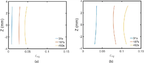
Axial equivalent Hencky strain profiles are shown for both experiments in Figure 8 at the same times. We can see that two more pronounced ballooning areas, located at the upper and lower side of the ROI, are visible for each specimen. A picture of the sample after the test is presented in Figure 6.a. The picture shows the so-called “butternut shape” of the specimen. These areas of larger strains are not located in the hottest region as expected. This behavior does not follow Norton’s creep that commonly describes metals creep behavior. It can be explained by the presence of a specific mechanism occurring in the dual phase domain: Grain Boundary Sliding (GBS). The beta phase nucleation and growth mainly occurs at the alpha-grains boundaries [8]. It has been shown in the literature [8], [9], [10] that, if the fraction of beta remains lower than about 10%, GBS may be observed at the alpha-beta interface. This specific mechanism leads to a strong increase of the strain rate which is not directly induced by the temperature increase but rather relates to the metallurgical state. In
ROI
Z
0
(a) (b)
both experiments, the center of the ROI is expected to reach the maximum alpha to beta transformation in the sample, which tends to inhibit the GBS mechanism. In cooler regions, the fraction of beta decreases and GBS is more pronounced. It is worth noting that the ballooning areas are located at the same position in the Simulated LOCA and Simulated post-DNB tests. GBS mechanism may not be thus specific to a particular accident.
Fig 8. Equivalent creep strains axial profiles at 31s, 187s and 492s for (a) Simulated LOCA test and (b) Simulated RIA post-DNB test.
Figure 8 shows also much higher strains in Simulated RIA post-DNB conditions than in Simulated LOCA conditions. The circumferential Hencky strain evolution at the center of the ROI (blue square Figure 6) is plotted in Figure 9.a for both experiments. Two creep domains can be observed. In the first one, the strain rate is important and decreases until its stabilization. Then, the strain rate remains constant till the test end. It clearly appears that the first domain of the Simulated RIA post-DNB experiment presents higher strain rates than in the Simulated LOCA conditions. At 50 seconds, the strain measured in the Simulated RIA post-DNB test is more than 3 times higher than in the Simulated LOCA test at the same time. Finally, both tests tend to a similar creep rate of around 3.3.10-5.s-1 in the second domain (Figure 9.b).
Fig 9. Evolution of 𝜀𝜃𝜃 (a) and associated strain rate (b) at the center of the ROI for RIA post-DNB and LOCA experiments (blue square Figure 6).
(a) (b)
4.
Conclusion and prospects
An experimental device was setup in order to simulate RIA post-DNB conditions on fresh fuel rods. It allows to achieve heating rates up to about 1000°C/s while an internal pressure is applied within the sample. Using two 12 MPx cameras, thermal and kinematics fields can be computed during the whole experiment with a frequency of 100Hz using NIR thermography and stereo-correlation measurements. Both full-field measurements are performed at exactly the same time and location.
Two main results are highlighted.
First, the presence of a creep mechanism, which does not follow common creep behavior is observed in the dual phase domain. Indeed, in the 935°C experiments, the higher strain rates are not located at the hottest regions. This mechanism is highlighted by the presence of two balloons aside of the hottest regions. This can be explained by the activation of grain boundary sliding as proposed by [8] that becomes dominant compared to diffusion or dislocation creep mechanisms. If GBS has already been observed in the dual phase domain of Zirconium alloys it is still difficult to model, especially during non-isothermal tests.
Second, the thermal transient applied to the fuel rod has a strong impact on its creep properties. Strain rates are more than three times higher in the first creep domain in Simulated RIA post-DNB conditions than in Simulated LOCA conditions. Several mechanisms may be linked to these differences (non-equilibrium metallurgical state history, dynamic recrystallization, grains growth…). From these results, it clearly appears that the impact on a thermal transient on the metallurgy has to be better understood in order to better forecast the mechanical behavior of the cladding during a RIA. Following on from this work, it is foreseen to characterize the phase transition kinetics at very high heating rates using a GLEEBLE dilatometry device.
Acknowledgments
The authors acknowledge the financial support of EDF for this work.
References
[1] T. Forgeron, J.-C. Brachet, F. Barcelo, et al. “Experiment and modeling of advanced fuel rod cladding behavior under LOCA conditions: Alpha-beta phase transformation kinetics and EDGAR methodology.” Zirconium in the nuclear industry, twelfth international symposium. ASTM International, 2000.
[2] A. R. Massih, “Transformation kinetics of zirconium alloys under non-isothermal conditions.” Journal of Nuclear Materials, 2009, vol. 384, no 3, p. 330-335.
[3] D. Campello, N. Tardif, M. Marwa, et al. “Identification of the steady state creep behavior of Zircaloy-4 claddings under simulated Loss-Of-Coolant Accident conditions based on a coupled experimental/numerical approach.” International Journal of Solids and Structures, 115, p. 190-199, 2017.
[4] D. Campello, N. Tardif, J. Desquines, et al. “Validation of a multi-modal setup for the study of Zirconium alloys claddings’ behavior under simulated LOCA conditions.” Strain, 1339, 2018. DOI:10.1111/str.12279
[5] N. Tardif, M. Coret, A. Combescure, “Experimental study of the fracture kinetics of a tubular 16MnNiMo5 steel specimen under biaxial loading at 900 and 1000°C. Application to the rupture of a vessel bottom head during a core meltdown accident in a pressurized water reactor,” Nuclear Engineering and Design, 241, 3, (2011), 755-766.
[6] J. Réthoré, T. Elguedj, P. Simon et al. « On the use of NURBS functions for displacement derivatives measurement by digital image correlation.” Experimental Mechanics, 2010, vol. 50, no 7, p. 1099-1116.
[7] B. Beaubier, J.-E. Dufour, F. Hild, et al. “CAD-based calibration and shape measurement with stereoDIC.” Experimental Mechanics, 54, no 3, p. 329-341, 2014.
[8] A. M. Garde, H. M. Chung, T. F Kassner. “Micrograin superplasticity in Zircaloy at 850°C.”
Acta Metallurgica, 1978, vol. 26, no 1, p. 153-166.
[9] D. Kaddour, S. Fréchinet, A.-F. Gourgues, et al. “Experimental determination of creep properties of zirconium alloys together with phase transformation.” Scripta materialia, 2004, vol. 51, no 6, p. 515-519.
[10] A. R. Massih, “High-temperature creep and superplasticity in zirconium alloys.” Journal
![Fig 1. Description of ELLIE device (a) Picture of the device [4]. (b) Scheme of the setup](https://thumb-eu.123doks.com/thumbv2/123doknet/8165456.274081/3.892.119.772.860.1169/fig-description-ellie-device-picture-device-scheme-setup.webp)
![Fig 4. Loading sequence for (a) LOCA process [3] and (b) RIA Post-DNB process](https://thumb-eu.123doks.com/thumbv2/123doknet/8165456.274081/5.892.103.831.310.527/fig-loading-sequence-loca-process-ria-post-process.webp)