HAL Id: hal-00719157
https://hal.archives-ouvertes.fr/hal-00719157
Submitted on 19 Jul 2012
HAL is a multi-disciplinary open access
archive for the deposit and dissemination of
sci-entific research documents, whether they are
pub-lished or not. The documents may come from
teaching and research institutions in France or
abroad, or from public or private research centers.
L’archive ouverte pluridisciplinaire HAL, est
destinée au dépôt et à la diffusion de documents
scientifiques de niveau recherche, publiés ou non,
émanant des établissements d’enseignement et de
recherche français ou étrangers, des laboratoires
publics ou privés.
Towards reconfigurable and modular microfactory based
on the TRING-module stick-slip microrobot.
Dominique Gendreau, Micky Rakotondrabe, Philippe Lutz
To cite this version:
Dominique Gendreau, Micky Rakotondrabe, Philippe Lutz. Towards reconfigurable and modular
microfactory based on the TRING-module stick-slip microrobot.. 8th International Workshop on
MicroFactories, IWMF’12., Jun 2012, Tampere, Finland. pp.1-5. �hal-00719157�
1. Introduction
A microfactory is a highly compact micromanufacturing system composed of micromachines and microrobots with very high precision. A microfactory transforms or assembles microparts in order to result microproducts. The resulting microproducts are often expensive due to the high complexity of assembly and fabrication of the microparts as their sizes are reduced and as the required precision of assembly is very severe (micrometric or sub-micrometric). In order to reduce the cost fabrication of microproducts and the cost of the microfactory itself, we present in this paper an approach for the design of a microfactory. Based on the concept of modularity of the elements (micromachines and microrobots) that compose the microfactory, this latter presents a high level of re-configurability and then can be easily used for a broad types of products to be fabricated.. The paper is particularly focused on the use of a 2-degrees of freedom (dof) microrobot named TRING-module microrobot developed in our previous works [1] as modular elements. Different configurations of the microfactory are therefore possible according to the combi-nation and the structure of the different TRING-modules used. The paper is organized as follows. In section-2, we present the TRING-module microrobot and its performances. Section-3 is devoted to a non exhaustive list of possible configurations of the microfactory based on the TRING-module. Finally, in section-4 we present a case example of configuration that is afterwards used for pick-and-place tasks commonly utilized in micro-assembly applications.
2. Presentation of the TRING-module
micro-robot
In this section, we present the microrobot TRING-module which will be used as modular element of the reconfigurable microfactory.
2.1 Kinematic and principle of motion
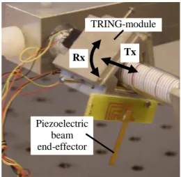
The TRING-module is a microrobot that has 2-degrees of freedom (2 dof): a linear motion along the x-axis (Tx) and an angular motion about the same axis (Rx) (Fig.1). The axis that supports the microrobot is a cylindrical glass. A cantilever is placed at the extremity of the TRING-module and used as end-effector that facilitates the handling of the manipulated objects. Developed in the previous work [1], the principle of movement of the TRING-module is based on the stick-slip functioning and uses piezoelectric micro-actuators described in [2]. The main features of the TRING-module are its theoretical unlimited stroke both in rotation and in translation, the high resolution that it can offer and its good dexterity (rotation and translation).
Fig. 1 A photography of the TRING-module.
2.2 Performances of the TRING-module
As a stick-slip microrobot, the TRING-module can perform the high stroke motion thanks to the step-by-step principle. This is obtained by applying a saw tooth voltage to the
!"
#
$% % &'
(
! )! " # $# % " % $ % " & ! & !
' ( ) * +( , - +! .) /00 012 34 124 5)/00 012 34 146
7 89 # ) ! ( : ! ! ; : ! # $< ! ! ;
Abstract – This paper deals with the presentation of a reconfigurable and modular microfactory based on a stick-slip microrobot called TRING-module and that can performs 2-degrees of freedom. The main advantage of the presented approach is that the microfactory can be quickly reconfigured in order to match with the requirements of the microproducts to be fabricated or to be assembled. This high reconfigurability is obtained thanks to the modularity imposed at the microrobot level. In particular, we demonstrate in this paper that based on only one duplicable microrobot (the TRING-module), several configurations of the microfactory are possible. The paper ends with an example of configuration based on two TRING-module microrobots followed by their characterization that can be further used for a controller design for pick-and-place tasks.
TRING-module
Piezoelectric beam end-effector
piezoelectric micro-actuators. The speed of the microrobot is proportional to both the frequency f and the amplitude U of the voltage, while the step-magnitude depends principally on the amplitude [3]. The high stroke motion is usually employed for a coarse positioning in a large distance. It is also possible to work within a step (sub-step). This sub-step motion, usually employed for fine positioning, is obtained by applying a voltage with limited slope to the micro-actuators. In sub-step motion, the resolution of the TRING-module is greatly amplified. The step-by-step motion and the sub-step motion can be managed and automatically switched by using the closed-loop control law developed in [3]. The principal advantage of the latter control law is the obtaining of high speed and high precision at the same time without manual reconfiguration of the controller. Tab.1 summarizes the performances of the TRING-module alone without closed-loop control [1][3][4]. It clearly shows the high performances of the microrobot in term of resolution and stroke and that are well suited to the requirements in microfactory in general. Motion Step
(=resolution)
Max Speed Stroke Linear 70nm 200nm 2mm/s unlimited Angular 17µrad 44µrad 3.4rpm unlimited
Table 1 Performances of the TRING-module microrobot [1][3][4]
2.3 Modules and modular element
The TRING-module itself is considered as a module in the proposed reconfigurable microfactory. Its principal functionality is the positioning. The end-effector of the TRING-module can also be considered as an active module if it has a function. For instance if a piezoelectric cantilever is used as end-effector, it can be used as manipulation force sensor at the same time, etc.
3. Reconfigurable microfactory based on the
TRING-module
By using one or more TRING-modules and by conveniently adapting their emplacement, it is possible to obtain various configurations of cell, station or microfactory. A configuration is generally used such that it corresponds to the optimal production of a given microproduct, in terms of yield, reliability, rate, or other criteria. In this section, we give some example of configurations based on the TRING-module. The configuration in Fig.2 represents one TRING-module with an end-effector. This configuration can be used in pick-
Fig. 2 Configuration with one TRING-module for pick-and-place tasks and for manipulation.
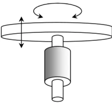
transport-and-place tasks of objects by using only the cantilever (end-effector). The task is possible if the objects are small enough such that they can stick on the end-effector. In Fig.3, the TRING-module is immobilized on the basis and the cylindrical glass that was initially the support is now the movable part. Hence, a platform placed at the extremity of the cylinder can rotate about or moves along the vertical axis Rz. This configuration can be used as a table to precisely place, orientate and position an object to be manipulated.
Fig. 3 Configuration with one TRING-module for linear and angular motions of a table.
To tilt the table, the configuration of Fig.3 is extended as shown in Fig.4. In this latter configuration three TRING-modules are used. According to the motion of the different TRING-modules, the table can be oriented in two directions: about Rx and about Ry axis. A vertical linear motion can also be made by moving in the same direction the three TRING-modules.
Fig. 4 Configuration with three TRING-modules for a tilt table.
In Fig.5 two independent TRING-modules are used for pick-and-place applications. The main advantage of this configuration is that the microgripper has a variable gap and therefore can manipulate various types and sizes of objects. The objects can be positioned along and about the axis of support of the microrobots. In addition to that, if the two TRING-modules rotate in opposite direction, the object can be oriented.
Fig. 5 Configuration with two TRING-modules for
pick-and-place tasks.
In Fig.6, we present a configuration where the two TRING-modules are immobilized on the basis and where a belt is moved by the two cylindrical glasses and can position in the plane any object. As the strokes of the microrobots are theoretically unlimited, the strokes obtained with the final conveyor are only limited by the length of the belt and the length of the movable cylindrical glasses.
Fig. 6 Configuration with two TRING-modules for xy-positioning.
The different configurations presented so far can also be mixed in order to obtain a more complex configuration of microfactory. For instance, in Fig.7, the configurations in Fig.5 and Fig.6 are combined. The advantage is that the cell, station or microfactory becomes more dexterous.
Fig. 7 A configuration that combines Fig.5 and Fig.6.
4. Study of a case of configuration
We consider the configuration of Fig.5 in this example. Experimental tests were successfully carried out and reported in this paper.
4.1 Presentation of the setup
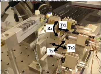
The two TRING-modules used for the setup is pictured in Fig.8. The end-effectors (also called fingers) are based on piezoelectric materials. If necessary, they can be used to measure and control the force applied to the manipulated
object thanks to the direct piezoelectric effect [5].
The challenge is to coordinate the movements of the two TRING-modules that carry an object between their end-effectors such that the object is still maintained during the transport. A first solution is to control the force additionally to the position. In such solution, one of the TRING-module is closed-loop or open-loop controlled in position while the other one is closed-loop controlled in force. This solution requires a force sensor put on the end-effector which increases the complexity of the design. The second solution consists to control the two devices in an open loop manner. During the linear motion for instance, one of the TRING-module functions as a pulling module while the another one as a pushing module. In this second solution, the control law consists in conveniently giving a speed reference to each TRING-module.
Fig. 8 The setup.
4.2 Precise characterization of one TRING-module
In order to open-loop control the two devices, it is essential to characterize their behaviors as precise as possible. Behind the characteristics listed in Tab.1, the velocity characteristics of each TRING-module are essential here.
Fig. 9 Identification of the displacement with a camera. The setup used for characterization is pictured in Fig.9. A camera records the successive positions of the end-effector of one TRING-module microrobot. A program developed with Matlab-Simulink® acquires the images of the end-effector, provides the contour plot with the Canny algorithm [6] and finally calculates its coordinates. Fig.10 gives the calculated position versus the time of the TRING-module.
y
x
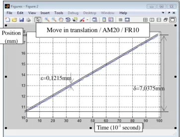
Tx1 Rx Tx2 Ty Pulling TRING-module2 Pushing TRING-module1 Finger1 Finger2 Direction of movement Rx TxFig. 10 Linear motions of one TRING-module. From Fig.10, an average speed of S1=0,704 mm/s is obtained
with the following parameters: AM20 (Amplitude=157,8 V), FR10 (Frequency=4261 Hz). As we can see, a very low displacement variance is seen. Indeed the displacement variance is bounded by 0.1215mm
4.3 Precise characterization of two TRING-modules
The sequence of transfer is said successful if the two fingers move at two equivalent speeds. It is therefore necessary to characterize the two TRING-modules. In particular it is of important to determine what are the input frequencies and input amplitudes to be applied and with which the two microrobots have the same speed. Indeed, they do not necessarily have the same speed for the same input voltage. This is due to small difference in design, etc. Several experiments were carried out for that (Fig.11) and we found that the with AM20 (Amplitude=157.8V) and FR14 (Frequency=3125 Hz) applied to both TRING-modules, they have the same speed.
Fig. 11 Velocity characteristics of the two TRING-modules.
5. Discussion
5.1 TRING-module principle
With the increasing need of precise tools for micro/nano-ma nip ulatio n, the microgripper structure based on two TRING-module we presented in this paper is new face to the existing industrial manipulators [7][8][9][10][11]. It has two main advantages: 1) the structure combines translation and rotation with the same microrobot which opens increases the possibilities of configurations of the microfactory; 2) different sizes and shapes of micro-objects can be manipulated thanks to the variable gap of the microgripper based on the two TRING-modules. The sizes of the micro-objects can vary from few tens of microns to some millimeters.
The slip-stick motion principle used allows a precise and high stroke displacement of the TRING-modules. During the rotation however, the weight of the TRING-modules can affects the displacement variance. Feature works include the design of new versions of the TRING-modules that account this aspect.
5.2 Design of microrobotic stations based on TRING-modules
We have presented some possible configurations of microfactory based on the TRING-module and we have focused on one of them as a case example. A feature work is now to provide a design method of the station itself. For instance, according to the microparts to be assembled, to the microproducts to be fabricated and to the scenario of assembly/fabrication, the design method will provide the optimal configuration of the station/microfactory knowing that the modular elements are one or several TRING-modules. For that we will start with the DF A technique (Design for Micro-Assembly) [12].
5.3 Control of the TRING-modules
As we saw in Tab.1, the performances in term of resolution and range of motion of a TRING-module are very interesting and convenient for the expected applications. In order to obtain the required precision during the pick-and-place tasks, the two TRING-modules that compose the station with the particular configuration in Fig.8 should be controlled. Two schemes of control exist: open-loop and closed-loop schemes. Closed-loop control techniques, for instance that presented in the previous work [3], allow the stick-slip TRING-module microrobot to be robust face to external disturbances and to any model uncertainties. These disturbances include for instance the interaction force between the microrobot and the manipulated object. However closed-loop control techniques are mainly limited to the lack of convenient sensors in micro/nano scale applications. Indeed precise enough sensors are bulky and expensive (e.g. interferometry, triangulation based optical sensors, etc.) while embeddable sensors (for instance strain gage) are fragile, with limited range and do not often provide the required resolution. This is why open-loop control techniques are recognized in micro/nano applications [13].
Move in translation / AM20 / FR10
Time (10-1 second)
Position (mm)
ε=0,1215mm
The control technique of the two TRING-modules used in this paper was an open-loop technique. The velocity is the output signal and the reference signal as well for each module. The success of the control mainly depends on the precision of the model to be used [14]. The characterization of the TRING-modules as detailed in Section-4 is to allow the obtaining of such precise model. Open-loop technique can be assumed to be efficient in our applications as long as the interaction force (manipulation force) between the end-effector and the objects to pick-transport-place is weak, which is the case when the objects are small [15].
5.4 Application to micro-assembly
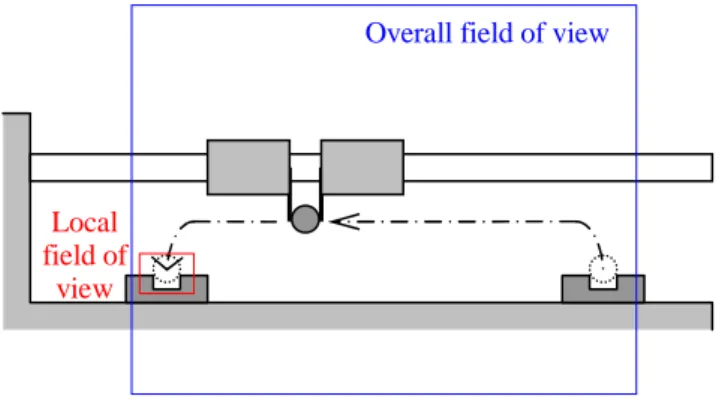
In the case of more complex task such as micro-assembly, a visual feedback may be required (Fig.12). This visual feedback is used to track the assembly operation between the transported object and the second (receptacle) object. To summarize, open-loop control techniques are used during the pic-transport of the object while a visual feedback technique is used during the release assembly. The main advantage is that a high speed is gained from the open-loop transportation while a high precision of assembly is obtained from the visual feedback. This application of micro-assembly will be implemented and tested in future works.
Fig. 12 Pick and place sequence.
6. Conclusion
This paper presented an approach to develop microfactory, cells or stations that can be reconfigured easily according to the requirement. Based on the modularity of the elements that compose the microfactory, we use a stick-slip microrobot called TRING-module as modular element. Several possible configurations were presented and one of them has been developed as a case example for a pick-and-place task. The experimental results showed the interest of the modularity aspect in this example, in particular the simplicity of control. Indeed, as the modules are similar (TRING-modules), the same control law can be applied to each of them. Future works include the experimental tests on other configuration of the microfactory and the realization of more complex tasks.
ACKNOWLEDGEMENT
This work is supported by the µUSINE-II-project.
REFERENCES
1. M. Rakotondrabe, Y. Haddab and P. Lutz, ”Development, Modeling, and Control of a Micro-/Nanopositioning 2-DOF Stick–Slip Device”, IEEE/ASME - Transactions on Mechatronics (T-mech), 14(6), pp. 733-745, Dec 2009. 2. A. Bergander, W. Driesen, T. Varidel and J.M. Breguet,
"Monolithic piezoelectric push-pull actuators for inertial drives", IEEE International Symposium Micro-mechatronics and Human Science, pp. 309-316, 2003. 3. M. Rakotondrabe, Y. Haddab and P. Lutz, “Voltage
/frequency proportional control of stick-slip microsystems”, IEEE - Transactions on Control Systems Technology (T-CST), 16(6), pp. 1316-1322, Nov 2008.
4. Li Ang, “Mise en œuvre d’une station de micro-manipulation”, MSc thesis, University of Franche-Comte in Besançon (UFC), 2011.
5. M. Rakotondrabe and Y. Le Gorrec, “Force control in piezoelectric microactuators using self scheduled H_inf technique”, IFAC - Mech, (Symposium on Mechatronic Systems), pp. 417-422, Cambridge Massachusetts USA, Sept 2010.
6. WANG Zhi, HE Sai-xian “An Adaptive Edge-detection Method Based on Canny Algorithm”, Journal of Image and Graphics, 2004-2008.
7. “Kleindiek Nanotechnik MM3A” http://www.nanotechnik.com/.
8. “Zyvex Nanomanipulator” http://www.zyvex.com/. 9. “Imina Techonologies miBot” http://www.imina.ch/. 10.“Attocube Nanopositioners” http://www.attocube.com/. 11.“Percipio Robotics” http://www.percipio-robotics.com/. 12.L.Benmayor, “Dimensional Analyse and Similitude in
Microsystem Design and Assembly”, PhThesis N°2232, EPFL, Lausanne, Switzerland, 2000.
13.B Borovic et al., “Open-loop versus closed-loop control of MEMS devices: choices and issues”, Journal of Micromechanics and Microengineering, Vol.15, N°10, 2005.
14.A.N. Das and D.O. Popa, “Precision Evaluation of Modular Multiscale Robots for Peg-in-Hole Microassembly Tasks”, 2011 IEEE/RSJ International Conference on Intelligent Robots and Systems, San Francisco, CA, USA, Sept 25-30, 2011.
15.Manikantan Nambi, Aayush Damani, and Jake J. Abbott, “Toward Intuitive Teleoperation of Micro/Nano-Manipulators with Piezoelectric Stick-Slip Actuators”, 2011 IEEE/RSJ International Conference on Intelligent Robots and Systems, San Francisco, CA, USA, September 25-30, 2011.
Overall field of view
Local field of