HAL Id: hal-01007176
https://hal.archives-ouvertes.fr/hal-01007176
Submitted on 18 Nov 2016HAL is a multi-disciplinary open access archive for the deposit and dissemination of sci-entific research documents, whether they are pub-lished or not. The documents may come from teaching and research institutions in France or abroad, or from public or private research centers.
L’archive ouverte pluridisciplinaire HAL, est destinée au dépôt et à la diffusion de documents scientifiques de niveau recherche, publiés ou non, émanant des établissements d’enseignement et de recherche français ou étrangers, des laboratoires publics ou privés.
Distributed under a Creative Commons Attribution| 4.0 International License
Part-circular surface cracks in round bars under tension,
bending and twisting
Anh Le Van, Jean Royer
To cite this version:
Anh Le Van, Jean Royer. Part-circular surface cracks in round bars under tension, bending and twisting. International Journal of Fracture, Springer Verlag, 1993, 61 (1), pp.71 - 99. �10.1007/BF00032340�. �hal-01007176�
Part-circular surface cracks in round bars under tension,
bending and twisting
A. LEVAN and J. ROYER
Laboratoire de Mecanique des Structures, Ecole Centrale de Nantes. 1 rue de Ia Noe, Nantes 44072 Cedex 03, France
Abstract. Circular-fronted cracks in round bars subject to tension, bending and twisting are considered. Numerical expressions are given allowing the calculation of stress intensity factors K., K1., Km at every point on the crack front
for a wide range of crack geometries. Comparisons are made with analytical, experimental and numerical results available in the literature. Crack shapes satisfying the iso-K1 criterion are also determined, making it possible to
investigate the problem of crack growth behaviour under tensile or bending fatigue loads.
1. Introduction
As cylindrical specimens are easily machined, components with a round cross section are commonly used in engineering structures. Bars, shafts, wires, reinforcements, bolts, screws or
pins are examples of cylindrically-shaped structural elements. In many applications the loading conditions are quite complex. Under cyclic or repeated loads, fatigue cracks can occur in such
components. Experimental works [1-5] showed that surface cracks created by fatigue have approximately circular fronts. In order to predict the growth of such a crack and the strength of the cracked component, an accurate stress analysis is required. Under linear elastic conditions, this leads us to precisely calculate the stress intensity factors which govern the mechanical state in the structure. In the general case of a combined load, a mixed mode I
+
II+
III situation exists along the crack front. As in any arbitrary three-dimensional configuration, the variation of stress intensity factors Kt. K11 , Km on the crack front must be taken into account.Several works have been devoted to the problem of a surface crack in a round bar. Table 1 summarizes the main features of some studies relating to this problem. In Table 1, K1A denotes the stress intensity factor at the deepest point of the crack, K18 the stress intensity factor at the surface terminal point (intersection between the lateral surface and the crack front),
K.
1 the average stress intensity factor calculated on the crack front. Additionally, straight-fronted cracks are considered as particular cases of circular or semi-elliptical cracks. The bibliography,although representative, makes no claim to completeness - rather, it is a selection of the many references found in this field.
In this paper, use is made of a boundary integral equation specifically developed for fracture
problems [22] to determine the stress intensity factors K1, K11 , K111 for circular-fronted cracks
in a round bar subjected to tension, bending and torsion. Polynomial expressions are provided
allowing the calculation of these stress intensity factors at every point on the crack front for a
wide range of crack geometries. Crack shapes satisfying the iso-K1 criterion are computed, and the problem of crack growth behaviour under tensile or bending fatigue loads is discussed. The
Table 1 . Summary review Experimental works Reference Crack geometry Load Method Main results Bush (t976) [6] Straight-fronted crack Three-point Compliance K., bending measurements Daoud et al. (1978) [7] Straight-fronted crack Tension Compliance K. l measurements Astiz et al. (1981) [8] Straight-fronted crack Tension Photoelasticity KIA Salah el din et al. Actual shape :::-::circular Tension and Fatigue tests KIA (1981) [2] fronta l crack bending Bush (1981) [9] Straight-fronted crack Tension Compliance K., measurements Athanassiadis et al. Actual s hape :::-:: circular Tension Compliance K 1 and the fracture (1981) [ 1
J
fronted or semi-elliptical measurements toughness K 1c crack + Fatigue tests Withem et a!. ( 1982) Actual shape :::-:: circular Tensio n Fatigue tests Kr [4] fronted crack Nezu et al. . ( 1982) [3] Actual shape :::-:: circular Tension Fatigue tests A power Ia w between fronted crack crack propagation rate da f dN and range of stress intens ity factor AK Forman et al. ( 198 6) [ 5] Actual shape :::-:: circular Tension and Fatigue tests K, fronted crack + 90 u bending intersecting angle Astiz et al. ( 1986) [tO] Actual sha pe :::-:: semi-Tension Fracture tests K 1 A at frac t ur e elliptical crack Numerical works Reference Crack geometry Load Method Main results Blackburn (1976) [11] Straight-fronted crack Tension and Finite element method Kr bending (FEM) Daoud ct al. (1978) [7] Straight-fronted crack Tension 2D-FEM and strain energy Kr release rate computation Astiz et at. (1980) [ 1 2] Straight-fronted crack Tension Stiffness deri vative K, method Salah ct din et al. Circular fronted crack Tension and FEM K 1 A and K., (1981) [2] bending K 1 by the displacement substit ution meth odAthanassiadis et al. Semi-elliptical crack Ten s ion , bending Boundary integral equation K 1 at v ariou s locations on (1981) [1] and compressive method the c rack front and K 1 lateral bending Nezu et al . (1982) [3] Circular fronted crack Tension FEM K 1A an d K 1 8 Fan et al. (1982) [13] Circular fronted crack Tension Alternati v e method b y K 1 along t he cr ac k f r o n t coupling two analytical solutions to analogous problems Daoud et al. (1984) [14] Straight-fronted crack Bending 2D-FEM and strain energ y
K
,
release rat e computation Daoud et al. (1985) [15] Circular fronted crack Tension and 2D-FEM and strain energy K, One special crack shape bending relea s e rate computation Raju et al. (1986) [16] Special crack geometries Tension and FEM K 1 along th e crack front (:::::; sem i-elliptical) + 90 ° bending K 1 by the nodal force intersecting angle method Nord et al. (1986) [17] Semi-elliptical crack Ten s ion and FEM K 1,.. and K 18 bending K 1 by the s tiffness derivative method Astiz et al. (1986) Semi-elliptical crack Tension FEM with incompatible K 1 al o ng the cr ac k front [10], [18] singular e lement Caspers et al. (1987) [ 19] Circular fronted crack Tension and FEM and the weight K,,.. and K 18 LATERAL bending function method Other works Reference Crack geometry Load Method Main r es ult s Underwood et al. Straight-fronted cra c k Three-po i nt Combination o f : T wo fitt i ng K 1 ex p ress io ns (1989) [20] bending • experimental r e s ults of f o r two span-di a m e ter Bush [6] r at ios • numerica l re s ults of Daoud et al. [14] • two semi-analytical limit solution s Si (1990) [21] Circular fronted and semi-Tension and Comparison o f different Propo s ition of a K .-factor elliptical c r acks bending works sol u tion v erif yi n g a h y p o thesis on the c r ac k growth beh a viourfor mode I crack problems. Comparisons are also made with analytical results for some limit configurations.
2. Formulation
2.1. Geometry
Figure 1 represents a round bar of radius R and height h ~ R containing in its median cross
section a surface crack. The crack front is part of a circle of radius R'. When R' equals the crack
depth a, the crack is a so-called semi-circular crack. On the other hand, when R' tends to
infinity, the crack is referred to as 'straight-fronted'. Any intermediate crack geometry between
the two above limiting cases can be defined by the crack shape parameter 11.- B0B/B0B1 ,
ex E [0, 1] (Fig. 2). The computation is carried out on 4 crack shapes: 11. = 0 (semi-circular),
!,
1
and
1
(straight-fronted). The two intermediate cracks have been determined in such a way thatthey divide arc B0N 1 into three equal sub-arcs. Six relative crack depths are considered:
a/
R = 0.04, 0.12, 0.24, 0.40, 0.60, 0.85. Since there are 4 crack shapes for each crack depth, 24 crack geometries are analyzed (Fig. 3).Fig. 1. Geometry.
2.2.
Loads
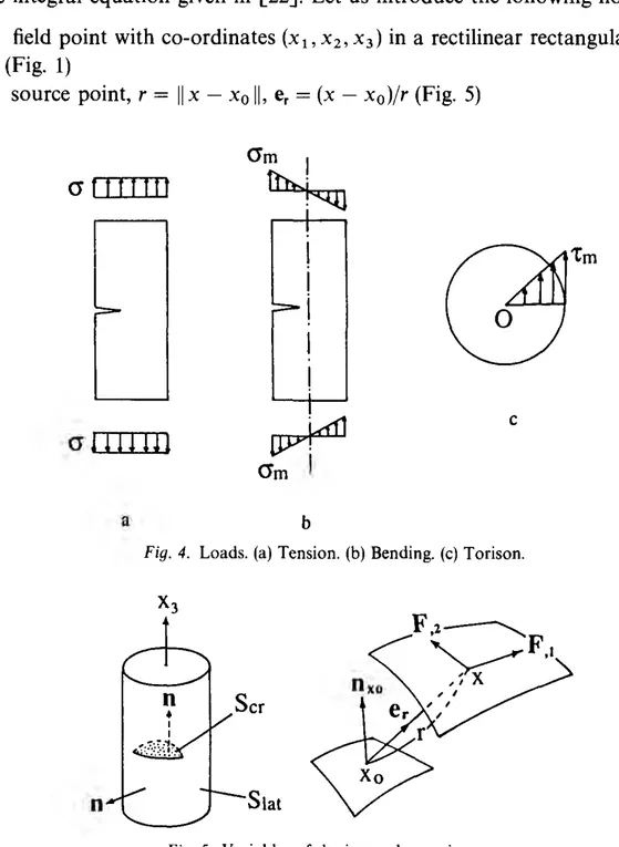
The bar is successively subjected at its ends to three loads (Fig. 4): • a uniform tensile stress
a.
• a linear tensile stress with outer fiber maximal value am.
• a linearly distributed shear with outer fiber maximal value rm, resulting from torques twisting the bar.
As far as stress intensity factor solutions are concerned, these loads are respectively equivalent to a uniform pressure, a linear pressure and an axisymmetricallinear shear applied on the crack faces.
2.3. Equations of the problem
The bar is assumed to be made up of a homogeneous, isotropic, linear elastic material characterized by Young's modulus E and Poisson's ratio v. For solving the problem use ts
made of the integral equation given in
[22].
Let us introduce the following notations:• x: field point with co-ordinates (x1 , x2 , x3 ) in a rectilinear rectangular system of axes
Oe1 e2 e3 (Fig. 1)
• x0 : source point, r =
II
x - x0II,
er = (x - x0)/r (Fig. 5)attftttf
crm
I
~
alllllll
~
<JmI
c a bFig. 4. Loads. (a) Tension. (b) Bending. (c) Torison.
F.z~
~F,,
, I X
n
Slat• t(x0 , nx0 ): the stress vector at x0 , related to normal Dxo·
• s .
cr· the surface of the crack, which is represented by a Cartesian parametrizationthe cylindrical lateral surface of the bar, which admits the parameterization
Flat: Lllat = [0, 2rr[ X [ -h, h] 3 (8, XJ)- X E slat·
In fact, the lateral surface S1at also includes the upper and lower flat bases of the bar, and
another surface must be added at the junction of the bases and the cylindrical surface (Fig. 6) in order to avoid any discontinuity of the normal vector on S1at· The outer surface of the bar is
then sufficiently smooth as required by the theory.
• <pcr:Scr3X-(/Jcr(X)EIR\ <plat:S
1
a1
3X~<p1
at(x)EIR3: the unknown densities defined respec-tively on Scr and S1a1 , which are shown to be equal to the displacement jumps through thesurfaces Scr and S1a1 respectively [23], [24].
• <l>cr
=
(/Jcr o Fen <l>lat=
<plato Flat (compounds of functions F and ({J).The set of equations of the problem can then be written in the following form, which ex-presses the stress vector at any point x0 and related to normal nxo, in terms of the densities <per
and (J)Jat:
( I )
where Ker cr and Ker1a1 are the kernels defined by
In relation (2), c:iik is the Levi-Civita symbol. The function F is defined by F: .L\ 3 (u1, u2)-+ x, a,
/JE{1,2}
For Kercr: (u 1, u2) = (xt. Xz), F = Fer• <I>= <l>cr> Dxo = e3
For Ker1at: (u1 , u2 ) = (8, x3 ), F = F1at• <I>= <1>1at• nxo is the outward normal at the point x0 to the lateral surface.
The symbol pv before
J
indicates that the integral is understood in the sense of the principal value.Partial derivatives of any function
f
with respect to variables ui is denoted f.i· Implicit summation is made over any repeated index.The stress vector at the point x0 is written in (1) as the sum of the surface intergals over the
crack and the lateral surface of the bar. Eventually one has to solve the coupled set of equations (1) with unknowns q>cr and ({>tat·
3. Numerical results
For all numerical purposes, the Poisson's ratio vis taken as equal to 0.3. Both the crack and the lateral surface are discretized into finite elements and Eqns. (1) are solved by the collection method. Figure 6 shows a typical mesh modelling the cracked bar. Eight-node or six-node isoparametric 20 elements are used throughout the structure. Quarter-point elements [25] are specifically used along the crack front. Depending on the surface to which the element belongs, the geometry transformation and the interpolation of the density are performed with different variables [26]:
- for elements belonging to the crack surface, the mapped variables through geometric transformation are Cartesian co-ordinates (x1, x2 )E ~cr and the interpolated functions are Cartesian components of ((>cr. q>~> q>2 and q>3
- for elements belonging to the lateral surface of the bar, the mapped variables are cylindrical coordinates (8, x3 ) E ~Jat and the interpolated functions are here again Cartesian components
of q>131 for simplicity. Cylindrical variables (8, x3 ) allow us to shape the finite elements into
curved
elements fitting the cylindrical surface. However, this cannot be seen in Fig. 6 since thesides of the elements are represented by segments.
The mesh covers the crack surface together with the lateral free surface. Of course, if the different loads were treated separately, then symmetries or skew-symmetries could be exploited in order to reduce the problem to the study of one quarter or one half of the bar, provided adequate boundary conditions are added. This approach is not chosen here for two reasons: first, the whole structure is preserved so that several loads can be applied simultaneously, thus requiring
only one solution of the algebraic system. Secondly, the matrix of the system being fully populated and moreover non-symmetrical (as is the case with any boundary integral equation method), obtaining symmetrical or skew-symmetrical final results ensures the accuracy of input data.
Eventually, the solution of the discretized equation of (1) provides the densities cpcr and
cp
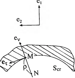
1a1, which in turn yield the complete elastic solution for the problem of the cracked bar, in particular the stress intensity factors can be evaluated along the crack front. Figure 7 shows the deformation of the lateral surface under a tensile load and of the crack under torsion. The latter is strongly emphasized in order to make it visible, explaining why some points on the crack seem to overlap the crack surface.The normalized stress intensity factors at any point located on the crack front are determined as follows, using the notations of Fig. 8:
(a) Case of a uniform pressure on the crack (tensile load):
~-K_,_
- I E 2 lim{(P3
{br}
= 2rr,/Jjj lim { E ,2cp
/
:_}'
a f o afo8(1 -v
)p~o
VP
a,_jrra p-->O 16rr(l-\ )...;p( 3.1)
a
b
Fig. 8. Determination of stress intensity factors. p = Distance to the crack front. e,: in-plane normal to the crack front, outward with respect to the crack. er: in-plane tangent, er = e3 1\ e,..
(b) case of a linear pressure on the crack (bending load):
1
E1. {
)¥n} _
2nfo1
.
{
E.!1!.2_}
2 Im <p 3 - Im 2 '
(Jmfo
8(1 - V ) p .... O p(Jmfo
p .... o 16n(l - V )JP
(3.2)
(c) case of a linear shear on the crack (torsion):
1
C ---,E1. {
)¥n} _
2nfo1. {
E~}
2=--
tm
<fJv - Ctm
2 r:, , Tmy na 8(1- v )p .... o p Tmy nap .... O 16n(l- v ) V p(3.3)
_K-=m= _
1
E lim{<p
{hr_2n}
= 2nfo (t _ v) lim { E _<fJ_t}rmfo rmfo
8(1+
v)p .... Ot~P
rmfo
p-o 16n(1- v2)JP '
(3.4)
where <fJv, <p0 <p3 are components of <fJcr in the local basis (ev, e" e3 ) generally varying along the
crack front (Fig. 8).
It should be mentioned that relations (3) are taken just as definitions for series intensity factors without any assumption on the elastic state at the point of interest. Neither plane stress nor plane strain states, which are certainly predominant at the neighbourhood of the free surface or the deepest point of the crack, are assumed. The transition from one state to another will not be discussed in this paper.
As shown by (2), solving (1) gives directly E/(16n(l - v2))<fJcr- the term bracketed together in
(3) - explaining why it is unnecessary to specify the value of Young's modulus E when computing stress intensity factors. Figure 9 shows the stress intensity factors obtained for the geometry corresponding to aj R = 0.4 and a = l, versus the relative abcissa sfsm (Folio wing the notations in Fig. 1, s is the curvilinear abcissa of a point on the crack front, sm is arc length AB, sfsm = -1 at B', =
+
1 at B).Thus, for each geometry, 4 discrete curves are obtained corresponding respectively to K1 in
tension, K, in bending, K11 and K111 in twisting. As predicted, the K1 value in the bending case is
always smaller than that in tensile loading at homologous points on the crack front. As for K111
values, they are found to be negative for all geometries. The negative sign of K111 is merely due to
the fact that <p3 equals the normal displacement at the upper crack face minus that at the lower face, and to the choice of the local basis orientation as shown in Fig. 8.
1.25 1.0 0.75 ~ "0 ~ 0.5 N
·
~-§
0.25 0z
0.0 ·0.25 ·0.5 0 0 ~ l!l['j!J 01!1 ·1.0 -0.75[ a/R=0.4
·0.5 ·0.25 0.0 0.25 0.5 0 (!b 0 1!1 1!)0a=t.l
0.75 1.0Fig. 9. Normalized stress intensity factors along the crack front. s = curvilinear abcissa, sm = arc length AB (see Fig. I).
Now using the least square method, the set of discrete values of stress intensity factors obtained for the 24 computed geometries are fitted in the following polynomial form:
K 3 3
(a)i (
s)k
(a) in the tension case:
fo
=I I
I
C~W-
ryJ -
,
(J rra i=Oj=O k=0.2.4.6 R Sm
K 3 3
(a)i (s)k
(b) in the bending case:
fo
=I I
I
Cl~~l - ry) - ,(Jm rra i=Oj=O k=0,2,4,6 R Sm
(4)
K 3 3
(a); ·( s
)k
(c) in the tension case: ):;;_ =
I I I
C~W-
lf.1 - ,r m rra i = 0 j = 0 k = 1' 3 R Sm
I I
3 3I
c~W) ~
()i (
ry_i.!... ,
)k
i=Oj=O k=0,2.4.6 R Sm
where the Ciik coefficients are given in Table 2. All mean quadratic errors resulting from the
fitting expressions (4) are about 1 percent, which is quite acceptable when compared to the accuracy of the finite element method. Expressions (4) should be used with crack depths of less than one-half diameter (0 ~ ajR ~ 0.9) and with lf.E [0, 1]. Figure 10 depicts the variation of
normalized stress intensity factors K1 in tension and Kn in torsion as a function of the crack
shape If. and the relative abcissa s/sm when the relative crack depth is 0.4. It is clearly shown that
for nearly straight-fronted cracks (If. ~ 1) K1 is maximum at the deepest point of the crack
(s/sm = 0), and for semi-circular cracks (If. ~ 0) the maximum value for K1 is reached in the
neighbourhood of the free surface
(ls
/
sml
~ 1). As for K11 , it varies almost linearly with either If. orTable 2. Ciik coefficients
j k
C!'.p
IJ C!'IJ .~' C!}~' j kC!W
for tension for bending for torsion for torsion
0 0 0 0.66837E + 00 0.67003£+00 -0.48863 E + 00 0 0 - 0.12653E+01 0 0 2 -0.12819£+00 -0.11851£+00 0.53272£ + 00 0 0 3 0.54361E+00 0 0 4 0.65362£ + 00 0.62139£+00 -0.66724£-01 0 1 1 0.28415£ +01 0 0 6 -0.63476£ +00 -0.60142E+00 -0.12661E +00 0 1 3 -0.89110£+00 0 0 0.14917£+01 0.14660£+01 -0.12523£ +01 0 2 -0.29326£+01 0 2 -0.15181£+01 -0.14844£ +01 -0.60349£ +00 0 2 3 0.10159£+01 0 4 0.17418£+01 0.17943£+01 -0.49469£ +01 0 3 1 0.11584£+01 0 1 6 -0.36700£ + 01 -0.36828£ +01 0.70620£+01 0 3 3 -0.66930£ +00 0 2 0 - 0.17108£ + 01 -0.16117£+01 0.15275£ + 01 1 0 1 0.81442£+00 0 2 2 0.34585£ + 01 0.34011 E+01 - 0.16732£ +00 0 3 -0.14275£+01 0 2 4 -0.11730£ +02 -0.11906£+02 0.17182£ + 02 1 1 -0.13862£+02 0 2 6 0.14317£+02 0.14447£+02 -0.22195£+02 1 3 0.55863£+01 0 3 0 0.67685£+00 0.61063£+00 -0.66148£+00 1 2 l 0.12860£ + 02 0 3 2 -0.22663£ + 01 - 0.22579E + 01 0.53588£ + 00 1 2 3 -0.21359£+01 0 3 4 0.85036£ + 01 0.86794E + 01 -0.11410£+02 l 3 I -0.25711£+01 0 3 6 -0.93203£+01 -0.94854£+01 0.14460£+02 1 3 3 -0.10148£ +00 1 0 0 0.27839£-01 -0.47133£ +00 0.36699£ + 00 2 0 -0.15475£+01 0 2 0.17235£+01 0.20042£ + 01 -0.43199£+00 2 0 3 0.22907£+01 0 4 - 0.62703£+01 -0.57214£+01 0.18574£ + 00 2 1 t 0.23260£ + 02 0 6 0.64590£ +01 0.57645£ + 01 -0.19042£+00 2 1 3 -0.87984£+01 1 0 -0.81658£ +01 -0.80954£+01 0.55393£ +01 2 2 I -0.15307£+02 1 2 0.17088E + 02 0.16657E + 02 -0.67371£ +01 2 2 3 -0.76504£+01 1 4 -0.47996£ +02 -0.46863E+02 0.48886£ + 02 2 3 1 -0.23390£+01 1 6 0.57275£ + 02 0.55311£ +02 -0.56251 E +02 2 3 3 0.10195£+02 2 0 0.18184£+02 0.16158£+02 -0.10060£ + 02 3 0 1 0.98730E + 00 2 2 -0.51812£ +02 -0.50220£+02 0.14305£+02 3 0 3 -0.16671£ +01 2 4 0.18923£+03 0.18476£ +03 -0.13617E +03 3 1 1 -0.13498£ +02 2 6 -0.20458£+03 -0.19806£+03 0.16139£+03 3 1 3 0.35067£ + 01 3 0 -0.10094£+02 -0.85514£ +01 0.49413£+01 3 2 1 0.53723£+01 3 2 0.34890£ + 02 0.33390£ + 02 -0.77503£+01 3 2 3 0.12547£ + 02 3 4 - 0.13413£ +03 -0.13068£+03 0.82669£ + 02 3 3 0.44763£+01 3 6 0.13902£ + 03 0.13465£ + 03 -0.99616£ +02 3 3 3 -0.12247£ +02 2 0 0 0.37008£ + 00 0.43077£ + 00 -0.16124£ +00 2 0 2 -0.48335£ +01 -0.43163£+01 0. 73697E- 01 2 0 4 0.18126£+02 0.15820£ + 02 0.44922£ + 00 2 0 6 -0.18218£+02 -0.15788£+02 -0.11729£ +00 2 0 0.15716£+02 0.15715£+02 -0.98606£ +01 2 1 2 - 0.33545E + 02 -0.35751£+02 0.20672£ + 02 2 1 4 0.94702£+02 0.10330£+03 -0.11358£+03 2 6 -0.11449£+03 -0.11960£ +03 0.11944£+03 2 2 0 -0.40103£+02 - 0.35295E + 02 0.19091£ +02 2 2 2 0.11148£+03 0.11409£+03 -0.37027£ +02 2 2 4 -0.40124£+03 -0.41823£ +03 0.27773£+03 2 2 6 0.43253£ + 03 0.44272£ + 03 -0.30932£ +03 2 3 0 0.23819£+02 0.19974£+02 -0.98142£+01 2 3 2 -0.77165£+02 -0.77778£ +02 0.16355£+02 2 3 4 0.29188£+03 0.30048E + 03 -0.15546£+03 2 3 6 -0.30135£+03 - 0.30666£ + 03 0.17910£ +03 3 0 0 0.18566£ + 00 - 0.80054£-01 0.55516£-01 3 0 2 0.40254£ + 01 0.31925£+01 0.56762£-01 3 0 4 -0.13204£+02 -0.11411£+02 -0.34231 E+OO 3 0 6 0.13326£+02 O.ll431E+02 0.97845E-01 3 0 - 0.76417£+01 -0.84732£+01 0.55027£+01 3 1 2 0.16116£+02 0.19953E +02 -0.14710£ +02 3 4 -0.37988£+02 -0.53843£ + 02 0.74788£+02
Tahlt! 2. con/d.
j k ( '(ijIl l k C\lljh t>l C\}~~ j k C\W
for tension for bending for torsion for torsion
3 6 0.50833E + 02 0.63937E+02 -0.74985E+02
3 2 0 0.23886E + 02 0.21101E+02 - 0.10877E+02
3 2 2 - 0.59707E + 02 - 0.67447E +02 0.24614E+02 3 2 4 0.20396 E + 03 0.24084E + 03 -0.16937E+03
3
.
,
6 - 0.22429E+03 - 0.25569E +03 O.l8007E+03 3 3 () - 0.13916E+02 --0.1 1863E+02 0.55202E+013 3 2 0.42030E + 02 0.46641 E + 02 - 0.96793E +01 3 3 4 - 0.156l6E+03 --0.17774E + 03 0.88809E +02 3 3 6 0.16211 E+03 0.18102E +03 --0.98112E+02
I
a/R=0.4l
a
aa
I
a/R=0.41
bFiy. 10. Stress intensity factors as a function of the crack shape Y. and the relative abcissa s;'s.,,. (a) Normalized K1 in tension. (b) Normalized K11 in torsion.
3.1. Stress intensity factors versus crack depth
Here, consideration will be limited to the deepest point where the stress intensity factors are given from (4) by putting s/sm = 0
KA C = " " L, L, Cijo R ex/,
(a)i .
(Jv
nu i j(5)
where K stands forK,, K11 or K111 and CJ also stands for CJm or Tm· Figure 11 shows normalized K"
K111 at the deepest point of the crack resulting from the basic loads - tension, bending and torsion- versus the relative crack depth a/R. Factor K11 is not plotted since it is identically zero
at
s
= 0. For each load there are four K, or K111 curves which relate individually to one crackshape, ::x = 0,
·
!,
1
or 1. It can be seen that the stress intensity factors vary continuously with the crack shape but they are not necessarily monotone functions of the crack depth. For instance in Fig. lla, the lower and upper curves related respectively to the semi-circular (a = 0) and the straight-fronted crack (::x = 1) show that normalized K,A increases with crack depth a, whereas the intermediate curves (::x=!
and a =1)
indicate that K,A, which certainly increases with a,2.5
ls=ol
I
s=O
I
KIA 1.25 crma 2.0 KIA 1.0 1.5 crrn fffii 0.75 1.0 0.5 C.!t~
0.25 0.0 0.0 0.0 0.1 0.2 0.3 0.4 0.5 0.6 0.7 0.1 0.8 0.0 0.1 0.2 0.3 0.4 0.5 0.8 0.7 o.a 0.8 aiR a/R 0 . 0 . . , . - - - , 0.0 0.1 0.2 0.3 0.4 o.s 0.6 0.7 0.8 0.8 a/Rdecreases for small crack depths when normalized by
a~.
It appears from Figs. 11a and bthat when
a
/
R takes the limit value zero, K1 at the deepest point takes almost the same value forthe crack shapes a = 1 and
!.
This would mean that, despite the notable change in radius ofcurvature- R' falling off from infinity when r:t. = 1 (straight-fronted crack) to a finite value when
a =
t
-
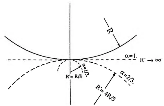
the stress intensity factors remain almost unchanged. In this respect, one can readilyestablish the limit value for radius R' when aj R tends to zero, the radius R of the bar and crack shape IJ'. being kept constant
(}.2
lim
R'
=
2 R.a/R--+0 J - 'Y.
(6)
Relation (6) gives both trivial results - for a
=
1, R' tends to infinity and for r:t.= 0,
R' tends to zero- and rather non-obvious results: for r:t. = iR' tends to R/8 = 0.125R and for 'Y. =fR
'
tendsto 4R/5
=
0.8R, as shown in Fig. 12.3.2. Stress intensity factors along the crack front - Application to the crack
growth behaviour problem
Figure 13 plots the normalized stress intensity factors versus relative abcissa
s
/
sm
along the crackfront, for the relative crack depth aj R = 0.4. Figure 13a shows more visibly than Fig. 10 that in
the case of a tensile loading, the curvature of the K1 curve changes in sign when passing from the
semi-circular crack ('Y. = 0) to the straight-fronted one (a = 1). Meanwhile, in this instance when
'Y. is approximately
-1,
a crack shape can be observed such that K1 remains virtually constantalong the crack front. This means that if the iso-K1 criterion is chosen to predict the propagation
of cracks created under mode I fatigue, the actual shape is that corresponding to 'Y. =
-t
.
Likewise, Fig. 13b shows that under a bending load the iso-K1 propagation criterion in this
instance leads to the shape corresponding to 'Y. =
j.
More precisely, for a given crack depth, the crack shape satisfying the iso-K1 criterion can be
computed in the following manner. Bearing in mind that R, a and a are constant, deriving
a=l.
- - - -;::_~_=:J~,_....f-.r-,JC#C::..::=-_·- - -R
I - - ) 00 ,__...,.,. ~,
'
'~...
~
I ' " ' / .,. . R'= R/8,~
; ''q.~
/'~
/,.
/
R~
~~~
I •. Oy---~ 1.25 0.1 0.1 1.0 0.7 l/3. 0.7S 0. _!S_
crma
0.4 0.5 0.3 0.25 \ a/R=0.4j 0.2I
a/R=0.4! 0.1 o.o-h-r-rrTT"I...-...,..,.'T"T"I...-...,..,...,..,:-r-r,....,...,.""I""T"'rT"T"1'"T"T...-i ·1.0 -4.7S -4.5 -o.25 0.0 0.25 0.5 0.7S 1.0 ~ - ~ .().25 ~ ~ ~ ~ u s/s,. s/Sm 0.7$ \ a/R=0.4j .0.1I
a/R=0.41 0.5 .0.2 0.25 .0.3 __!StL_ -cma-o
.
•
m .0.25 .0.5 .0.6 I. -o.JS .0.7·t.o -o.7S -o.s -o.25 o.o a.25 o.5 o.JS 1.0 ·1.0 .O.JS .0.5 .0.25 0.0 0.25 0.5 0.7$ 1.0
S/Sm S/Sm
Fig. 13. Normalized stress intensity factors versus the relative abcissa on the crack front. (a) K1 in tension. (b) K1 in
bending. (c) K11 in torsion. (d) Km in torsion.
expression for K1 given in (4) with respect to the relative abcissa
s
/
sm
yieldsa
K
(
a
)i (
s
)k-
1 ( 1 ) =afo~ ~
I
kCiik Ra/
-a
.!__ I 1 k :;;. 1 Sm Sm(7)
As it is clear that the derivative of K, cannot be identically equated to zero for all values of
s/sm
E [ -1, 1], the solution crack shape rx is such that it minimizes maxII
a
K
tfa(s
f
s
m
)ll,
i.e. rx is thesolution of the min-max condition
(a)i
·(
s)k-t
min max
I I
I
kCiik - rt.1 -ae[O,l] s/sme[- 1.1] i j k;;.l R Sm(8)
In order to outline the crack propagation during mode I fatigue, (8) is approximately solved and the results obtained are within 5 percent accuracy. Table 3 lists the solution crack shapes rx for the relative crack depths aj R considered in this paper.
Figure 14 compares the crack shapes predicted by the iso-K, criterion with those of the cracks
Tahle 3. Crack shapes verifying the iso-K1 criterion. Comparison with right angle cracks a/R 0.04 0.12 0.24 0.40 0.60 0.1<5 lso-K1 Y. 0.0~ 0.06 0.14 0.30 0.42 0.70 criterion in TENSION R',·R 0.048 0.147 0.331 0.694 1.172 2.940 Iso-K, :X I 0.04 0.10 0.29 0.47 (}59 0.70 criterion in BENDING R':R 0.051 0.161< 0.481 1.028 1.756 J.o97 Right intersecting 'l. 0.003 0.02 ().()7 0.17 0.36 0.73 angle criterion R'/R 0.04! 0.128 0.278 0.533 1.050 J25X
a - tensile fatigue
b
-
bending fatigue
iso-K
1criterion
-
-
- --
right intersecting angle criterion ('V=90°)
Fiq. 14. Prediction of crack growth under mode I fatigue.
as 90c (intersecting) angle cracks. For such cracks, 1/J
=
90(; (Fig. I) and one can readily prove that the crack radius R' is related to the radius R of the bar and the crack depth a by the relation, a(2R - a)
R = - --- -.
2(R - a)
(9)
It can be observed that the difference between
i
so-
K,
cracks and 90: angle ones is fairly small inthe case of tension (Fig. 14a) whereas this difference becomes notable for medium-sized cracks
under bending (Fig. 14b). This would mean that in tensile load fatigue tests, cracks verifying the
iso-K, criterion are almost 90" angle cracks, while in bending fatigue tests this is true only for
cracks with very small or very large depths. It should be remembered that this assessment has
been made with v equal to 0.3, and that the study of the influence of Poisson's ratio on the shape
Figures 15, 16 show the change in shape as the crack depth increases during the propagation. At the crack initiation, the crack is almost semi-circular. The further it grows up, i.e. the more the crack depth increases, the more it resembles a straight-fronted crack. Also represented in Figs. 15, 16 are the following stress intensity factors for a 90° angle crack: K 1 at the deepest point 1 (in this
case it is the minimum K, on the crack front) and the average K1 denoted by
K
1(10)
It is clearly shown in Fig. 15 that for 90° angle cracks under tension, K1A is approximately
K,
(the curves e and fare quite the same) and again one can recognize that 90° angle cracks verify the iso-K1 criterion. On the other hand, Fig. 16 shows that in the bending case, 90° angle cracksverify the iso-K1 criterion only for ajR ~ 0 and ajR ~ 0.9.
Figures 13c and 13d show the stress intensity factors K11 and K111 arising from a twisting moment applied at the ends of the bar. As already mentioned, K11 varies almost as a linear
function of the curvilinear abcissa s. On the other hand, for all crack shapes the absolute value of K m is maximal at the deepest point. In any case, the aspect of K 11 and K 111 curves are little
influenced by the crack shape, contrary to what happens to K1• Regarding the crack propaga-tion behaviour with the presence of anti-plane shear, experimental investigapropaga-tions in pure mode III by [27] clearly show that the crack no longer grows by extending in its own plane but by
Fig. 15. Normalized K1 in tension at the deepest point and average normalized K1 for different crack shapes.
Comparison with K1 computed from the iso-K1 criterion. (a) K1 at the deepest point for semi-circular cracks. (b) Average K1 for semi-circular cracks. (c) K 1 at the deepest point for straight-fronted cracks. (d) Average K1 for straight-fronted cracks. (e) K1 at the deepest point for right angle cracks. (f) Average K1 for right angle cracks. (g) K1 for cracks verifying the iso-K1 criterion.
Q
~ 1.0 ~ 0 N·-
c;
0.75e
~
0.5 0.250
-O.O-h-r-r..,...,..,.-r-r,_....,...,...,.."l"TT"T"T"T"T"T"T"T"T'T"'rT"'I"'T'"'r-T"'r-T"'rT'In-I_,...,"'T"i 0.0 0.1 0.2 0.3 0.<4 0.5 0.6 0.7 0.8 0.9a/R
Fig. 16. Analogous to Fig. 15, the loading is now a bending.
generating multiple penny-shaped cracks which straddle the original crack front. The study of the crack deviation in a bar under torsion must be even more difficult at the points on the front, where Kn and K111 take comparable values. Similarly, under combined tensile and
anti-plane shear loading (mode I
+
III), the crack grows by developing multiple lance-like fracture facets surrounding the crack front, as shown in [28]. These observations should be taken into account when the crack instability is studied under general loading conditions.Lastly, it is noteworthy that the provided stress intensity factors values are valid only over about 80 percent of the crack front length. The K values for sfsm approaching
+
1 are affected by phenomena extraneous to the present work, such as the vicinity of the surface terminal points B or B' (Fig. 1) that modifies the crack tip singularity. Also, the poor refinement of the finite element mesh around these zones must lower the accuracy of the numerical results. In any event, the results obtained in [29] prove that the crack tip singularity at the surface point depends on the Poisson ratio v and the terminal point incident angle 1/J (see Fig. 1) between the crack front and the surface line BB'. For a given value of v, there exists a limiting value of 1/J for which the stress intensity factor K1 tends to a non zero finite value. If 1/J is less than this limit value, K 1 fallsoff to zero and if 1/J is greater, K1 becomes infinite. In both cases K, classically defined loses its
physical meaning.
4. Comparison with theoretical results
No theoretical results are available for surface cracks in round bars. However, stress intensity factors at the deepest point (point A in Fig. 1) of very shallow straight-fronted cracks can be
effectively compared with analytical solutions for the single-edge crack in the half-space. This is due to the likeness between the latter geometry and the crack configuration viewed from point A when aj R tends to zero.
4.1. Bar under tension
The theoretical value for an edge crack of length a under a uniform pressure (J is given by Koiter [30]
K1 =
1.1215(J~.
On the other hand, making a/R tend to zero in (5) gives
I. KIA - '\'
c<It>
jIm c _ - ~ OjOCX,
ajR-+0 (JV 1ta j
which yields the limit value of normalized K1 at deepest point A of straight-fronted cracks
lim
fo
~
L
cgyo
~
uz6.
ajR-+O,rz= 1 (J na j
(11)
(12)
(13)
This value agrees well with the theoretical value (11) within an error of +0.4 percent. As regards the limit value of K1A for semi-circular cracks when ajR tends to zero, one expects it to be greater than the theoretical value
2
/
n
= 0.6366 for the penny-shaped crack embedded in the infinite body, as is easily explained by the presence of the free lateral surface of the bar which must allow a wider crack opening, thus a greater K1A· Indeed, here the limit value forsemi-circular cracks is found to be 0.668, which is about 5 percent higher than the foregoing analytical value
2
/
n.
Further, deriving expression (5) gives
lA _ . (It a i
a
(
K ) ( )i-1
a(a/R) (Jfo -
i
~1 ~ rC,i~
Ra
.
(14)Hence the slopes at ajR = 0 of the normalized K1A curves are
I.
a
(
KIA )c<H>
o
028 -1
201m a( /R) C.
=
1 oo=
.
= tan afR -+O,rz = 0 a (J V na(15)
(16)
respectively for semi-circular and straight-fronted cracks. These are quite small values that compare well with the zero slope drawn from relation (11), lim a(Kd(Jfo)/a(a/R)
=
0.4.2. Bar under bending
From Table 2 one obtains the limit value of normalized K 1 at deepest point A of straight-fronted
cracks in the case of bending load
( 17)
This agrees well with Koiter's theoretical value [30] which is also valid in the bending case,
within an error of
+
l percent. Note that the slopes at a/R = 0 for semi-circular andstraight-fronted cracks can also be computed in a similar way as in tensile loading
lim
a
(
K,
~)
=
C\'gb
= - 0.471 = tan-1( -25"), a!R-+0.2=0 o(ajR) amJna ( 18) lim 2 (K'';-)
="LC\'J6
= -0.961 = tan- 1(-44"), a/R-+0,7 = lo(a
/
R)()myna
J ( 19)although no easy comparison with theoretical values is possible to our knowledge.
4.3. Bar under torsion
Lastly, consider an edge crack of length a in the semi-infinite space, subjected to a uniform shear
r parallel to the crack front. The analytical result for the problem is given in [31]
r;--:
K,
11 = - Ty'(rra). (20)Applying the same reasoning to (5) as in proving (13), one obtains
lim
KIIIA =L
cg~~
= - 0.875.a/R-+0 .. 7= 1!
f;;z
1· mv(21)
This value is 13 percent higher than the theoretical value - I. The difference can be accounted
for by the fact that the shear is in-plane stress. In Fig. 17, the hatched area represents the
a
bdifference between the problem of a shallow crack in a round bar and that of an edge crack in the semi-infinite medium. In mode I problems, the applied stresses are normal to this area and their effect can be neglected around the deepest point A of interest. On the contrary, in mode III problems the stresses are parallel to the crack front, hence they may have some influence on K111 at point A though applied on an area geographically remote.
5. Comparison with experimental results
Available results in the literature are mainly concerned with mode I and points A, B on the crack fr~ .. ~ (Fig. 1). Sometimes, K1 is even assumed to be constant on the crack front so that only the average value is considered. Therefore, the somparison with either experimental or numericai results can be made only in the tension and bending cases. Also, as discussed above, stress intensity factor values at the surface terminal point B will be discarded and only the values at the deepest point A- or the average values whenever they are given- are compared. We shall denote the diameter of the bar by D, D = 2R.
5.1. Bar under tension
Figure 18 compares
K,
value of the present work with other authors' experimental values which are summarized below.• Straight-fronted cracks
By the compliance method Daoud et al. [7] give the average normalized
K,
for straight-fronted crack(22)
Table 4 gives the normalized K1 at the deepest point A by photoelasticity determined by Astiz et al. [8]. In fact, the value 1.85 corresponding to aj D = 0.45 in this table will not be retained here as it is unreliable according to [8].
Bush [9] gives the compliance expression c in terms of the relative crack depth a/D
c
= 0.0598723+
0.2680344(;r·+
0.2508381(;r
+
39.43071(;f.
(23)which provides the average normalized
K,
via the following relationK,
fi
(
E D l de)o
.
s
af o =
A
l - v2 4 [a/D - (a/D)2]0·5 d(a/D)4
-D
2.5
i
G
QKIA
2.0 ~!
~ 0 1.5 N·-
-
~e
0 1.0z
KlK,
G
0.5Q
0.0 0.0 0.1 0.2 0.3 0.4 0.5 0.6 0.7 0.8 0.9a/R
Fig. 18. Comparison with experimental results for K1 in tension: -8--: Daoud ct al. [7].
e
:
Astiz et al. [8]. - +- +Bush [9]. --G--G--: Wilhem et al. [4]. ~- : Forman et al. [5], [32]. -- : Present results (a) Average K1 for
semi-circular cracks. (b) Average K1 for right angle cracks. (c) Average K1 for straight-fronted cracks. (d) K1 at the deepest point for straight-fronted cracks.
The unity for compliance c in (23) is 10- 6 injlbf, Young's modulus in (24) is 10.6 x 10⁶ psi, and
D = 3 in. Attention should be drawn to the fact that in [9] the Poisson ratio is 0.32 and not 0.3
as assumed throughout this paper. However, the results are expected to be close enough to be
comparable.
• Cracks intersecting the lateral surface at right angles
(t/1
= 90°, Fig. I}A special fatigue marking technique to outline the crack propagating allowed Wilhem et al. [ 4]
to express the normalized K, for right angle cracks, constant along the crack front, as
K,
C.= 0.690-0.197-a
+
2.394 -(a)
2+
1.965(a)3
- , 0.15<
ajD<
0.45.(Jv
na D D D (25)Experiments conducted on fatigue cracks led Forman et al. [5], [32] to approximate the same
quantity as K, 2
c:
= 0.92 -(Jy ILU 1t na tan-2D na 2D 1 [ a ( .na)
3 ] 0.752+
2.02-+
0.37 1- sm- . na D 2D cos -2D(26) is reported as having good accuracy for a/D ~ I, reasonable accuracy for a/D <
t
.
Table 4. Normalized K1 at the deepest point of straight-fronted cracks [8] a/D 0.45 0.21 0.30 1.85 1.10 1.45 0.39 0.41 1.63 1.77 0.46 1.91 l st series 2nd series 0.06 1.15 0.95 0.12 1.02 1.23 0.31 !.58 1.41 0.42 1.89 1.69
Fig. 19. Comparison with experimental results for K1 in bending: --8- : Bush [6]. - + - + - : Forman et al.
[5]. :Present results (a) Average K1 for semi-circular cracks. (b) Average K1 for right angle cracks. (c) Average K1
for straight-fronted cracks.
Figure 18 shows a good agreement between different results for small crack depths. Regarding large crack depths, other workers' results relating to 90° angle cracks are rather closer to present K1 for semi-circular cracks. As for straight-fronted cracks, the discrepancy becomes notable for large crack depths too.
5.2. Bar under bending
• Straightjronted cracks
By means of compliance measurements Bush [6] provides the following equation for calculating the average stress intensity factor in the case of bending load
where the compliance c is determined by either expression
c = 4.338749
+
23.66921(~)
2
'
+
131.0767(~
r
oo
-•
in
j
lbf).
(28)c = 0.2910587
+
2.54535(~
) ' 'oo
-
•
in
/
lbf).
(29)Here again, E
=
I 0.6 x 10⁶ psi. and v=
0.32. Relation (28) is used with diameter D=
3 in, relation (29) with D = 6 in. In both relations, length I is about 10 in.• Cracks intersecting the lateral swface at right angles
Experiments conducted on fatigue cracks led Forman et al. [5] to the following approximate
expression for the normalized K1 constant along the crack front
K,
2-
-
,....--
=
0.92 -(}m)na n na tan -2D na 2D 1 na[0.923+
0.199(1-sin;~)]
cos- · 2Dwith the same accuracy reported above for the bar under tension.
(30)
• The comparison with all the available results for the bar under bending are shown in Fig. 19. For 90c angle cracks, a good agreement is observed at small crack depths only. As the crack depth increases, the experimental curve is rather closer to ours computed for semi-circular cracks. This remark agrees with Caspers et al.'s [19] following which 'the theory of perpendicu-lar angles between crack front and shaft circumference seems to be approximately correct for pure bending up to an aj R-ratio of 1.0, but does not seem to be so applicable for tension, especially for increasing a/R-ratios'.
Concerning the straight-fronted cracks, the computed curve is within the range of Bush's
experimental ones. Lastly, it should be mentioned that straight-fronted cracks do not exist
naturally and they are actually very difficult to obtain in experimental works. In most cases, a sharp notch was machined to simulate the crack [6-9]. As the machined notch must be wider
for a larger notch depth, it is unlikely to be comparable with a real crack. This should explain why the results agree less for large crack depths.
6. Comparison with numerical results
Here again, the comparisons are made in tension and bending cases. Moreover, only the K1 at
the deepest point or its mean value is reported.
6.1. Bar under tension
Figure 20 shows all the numerical results for the case of a tensile load. Astiz [ 18] considered semi-elliptic cracks with axes a, h. The normalized K1 factor at the deepest point A is given as a
2.5
r
G
Q
l
0.5
a/R
Fig. 20. Comparison with other numerical results for K1 in tension: ---8-···· : Daoud et al. [7].
e :
Raju et al. [16].- + - + : Astiz [18].- B-: Caspers eta!. [19]. --:Present results (a) K1 at the deepest point for semi-circular
cracks. (b) Average K1 for straight-fronted cracks. (c) K1 at the deepest point for straight-fronted cracks.
polynomial function of the crack depth ajD and the aspect ratio ajb
KIA _
I
±
c i j(.9:_)i(~)j·
(]Fa
i=O,i#l j=O D b(31)
The configurations which are comparable with those considered in this paper correspond to
ajb
=
1 (semi-circular cracks) and ajb=
0 (straight-fronted cracks).Investigating part-circular cracks, Caspers et al. [ 19] also gives normalized K1 at the deepest
point in the polynomial form
K lA =
L
4I,
5 CV) ( az ' ) " ( )"~
J(]Fa
i = 0 j = 1 IJ R 1t ,(32)
where az =a- R(l -cos 8), (J is the angle at the centre sustended by the arc BB' (Fig. 1).
Raju et al. [16] considered nearly semi-elliptical cracks such that the crack front intersected
the lateral surface of the bar at 90° angles. It should be noticed that the so-called crack length in
Tah/e 5. Normalized stress intensity factor at the deepest point [16]
ajD 0.050 0.125 0.200 0.275 0.350
'2 K I
c
7T.j X IA/<Jy 7T.a tensile load 1.012 1.015 1.038 1.087 1.175
this reference is defined as the arc length measured along the cylindrical surface and not as the major axis of the (nearly) elliptic crack. Thus the results of this reference for ajc = l
must be compared to others keeping in mind the difference between the analyzed
geo-metries. The normalized stress intensity factor at point A for ajc = I are listed in
Table 5.
• Straight-fronted cracks
Daoud et al. [7] computed K1 assumed to be constant along the crack front
K
1a
(a)
2(a)
3(a)
4 ---=~= = 1.11- 3.59-+
24.87 - - 53.39 -+
57.23 - , 0.06 ~ajD ~
0.7.aJna
D D D D (33)6.2. Bar under bending
Figure 21 shows all the numerical results for the case of a bending load. The normalized K1 at
point A for ajc = I from Raju et al.'s work [16] is given in Table 5.
Considering a lateral bending load, Caspers et al. [19] express K1 at the deepest point in the same polynomial form as for tension load
(34) 1.5
...-...
1.25G
G
KaA..__
~ 1.0 "'0 Q.) N 0.75·-
-
~E
--o--o--0 8 ":··:&--~-&--0~ a-0•
z
0.5•
•
•
KIA 0.25Q
a/R
Fig. 21. Comparison with other numerical results for K1 in bending: 0 :Daoud et al. [14]. e: Raju et al. [16].
0 :Caspers eta!. [19]. ---- : Present results (a) K1 at the deepest point for semi-circular cracks. (b) Average K1 for straight-fronted cracks. (c) K, at the deepest point for straight-fronted cracks.
Table 6. Normalized K1 at the deepest point for a semi-circular crack in the half-space under tensile load. In parentheses: value given in the bending case.
Percent difference =(present result/referenced result - I) x 100
Reference Smith et al. Newman Nisitani et al. Newman et al. lsida et al. Present (1967) [33] (1973) [34] (1974) [35] (1981) [36] (1984) [37] result
KIA!(JJ(rra) 0.656 0.656 0.636 0.662 0.659 0.668
(0.662) (0.659) (0.670)
Difference 2 2 5 1.4
(percent)
It should be mentioned that in [19] the linearly distributed stress is zero at the deepest point
level (x1 = - R
+a,
Fig. 1) and not at the diameter level (x1 = 0). An adequate combination of(32) and (34) must be carried out to obtain the results for the bending case.
• Straight-fronted cracks
Daoud et al. [14] computed the average
K,
over the crack front"m}a
=1.04-3.64
~
+
16.86(~)'
_
32.59(~)'
+
28.41
(~r
0.0625 ~ a/D ~ 0.625. (35)
• Figures 20 and 21 show a good agreement between different numerical results concerning
semi-circular cracks, both in tension and bending cases. As regards straight-fronted cracks, the
results agree well only for small crack depths. It should be mentioned that KrA values for
straight-fronted cracks given in [19] are rather low and thus are closer to
K
1•• Limiting configuration of very small semi-circular cracks
Let us now consider the limiting case when the radius of the semi-circular crack R' = a tends
to zero. The limit value of K1 at the deepest point A is found to be 0.668 and 0.670,
respectively, for the tensile and bending load. On the other hand, since this value must be the
same as for a semi-circular crack in the half-space, it can be compared to the limit values
obtained by earlier investigators treating the half-space problem. Table 6 shows that the
differences are really small, except for Nisitani et al.'s value which amounts to 5 percent above
the present result.
7. Conclusion
The obtained results have brought additional information to the problem of the elastic cracked
bar, especially in mode I. A methodical use of integral equations has proved efficient in that it
allows the following possibilities:
- the computation of stress intensity factors at any point of the crack front (except for the
surface terminating points),
- the polynomial fitting of numerical values providing the stress intensity factors as functions of three geometrical parameters: the crack depth
a,
the crack radius R' and the abscissas
measured on the crack front,
- the results applicable to three basic loads: tension, bending and torsion.
Limiting values of stress intensity factors when the crack depth tends to zero have been found to be in full agreement with the theoretical values for the half-space problem. Furthermore, the numerical values have been compared with both experimental and numerical results available in the literature, which are mainly concerned with the opening mode. A good agreement between the different results has been observed for small crack depths. Nevertheless, for large crack depths for factor K, increases more rapidly than others. The discrepancy is the more important for straight-fronted cracks.
Since no comparison is possible in modes II and III, it is assumed that the computation which is validated in mode I, also gives acceptable results for other modes. In fact, tests conducted on problems having known analytical solutions have shown that the numerical accuracy is higher in mode I problems than in others.
The polynomial fitting of the results has allowed a rapid and accurate calculation of the stress intensity factors as a function of the crack configuration and the applied loads. Also, the knowledge of these factors all along the crack front has made it possible to investigate either elastic fracture criteria or the fatigue crack growth behaviour. As an application of the results, the crack shapes verifying the iso-K1 criterion have been computed in mode I fatigue problems.
Of course, the obtained results are not influenced by the Young modulus value but they do depend on Poisson's ratio v as shown by the governing equations (I) and (2). The computation has been carried out with
v
equal to 0.3.The effect of Poisson's ratio upon the crack shape can be investigated as an extension of the present work. Besides, the proposed integral equation formulation can be applied without major modifications to the problem of thick-walled cylinders containing through- or part-through cracks.
References
!. A. Athanassiadis. J.M. Boissenot, P. Brevet, D. Fran~ois and A. Raharinaivo. International Journal of Fracwre 17, 6
{1981) 553-566.
2. A.S. Salah el din and J.M. Lovegrove, international Journal of Fatigue 3 (1981) 117-123.
3. K. Nezu. S. Machida and H. Nakamura, in The 25th Japan Conyress 011 Material Research. Metallic Metals ( 1982) 87-92.
4. D. Wilhem, J. FitzGerald, J. Carter and D. Dittmer, in Adt•ann:s in Fracture Research · Fracture X 1. Proceedin~Js of the 5th International Conference on Fracture Research (ICF-5), D. Fran~ois (ed.), Pergamon Press (1982) 11-21.
5. R.G. Forman and V. Skivakumar, in Fraelure Mechanics. vol. 17, ASTM STP 905, 17th National Symposium on Fracture Mechanics, Albany. New York (I 986) 59-74.
6. A.J. Bush, in Proceedings o( the Society .fiJr Experimental Stress Analysis 33, 2 ( 1976) 249-257.
7. O.E.K. Daoud, D.J. Cartwright and M. Carney, Journal of' Strain Analysis 13, 2 (1978) 83-89.
8. M. Astiz, M. Elices, J. Morton and A. Valiente, in Proceedinys o(the Societ_vfhr Experimental Su·e.~.~· Analysis, Spriny Meeting, Dearborn, Michigan ( 198 I) 277-282.
9. A.J. Bush, Journal o( Testing t.md Eraluation 9, 4. 1 uly (I 98 I) 2 I 6-233.
10. M.A. Astiz, M. Elices and A. Valiente. t.'uropean Conyress on Fracture (EC F-6) ( 1986) 65-74. II. W.S. Blackburn, Engineeriny Fracture Mechw1ics 8 ( 1976) 73 I 736.
12. M.A. Astiz and M. Elices. in Proceedings of £he Second Infernal ion a/ Conference on N umerica/ lvl et lwds in FraCTure Mechanics. Pincridge Press, Swansea ( 1980) 93 I 06.
13. Y-X. Fan, Y-T. Fan and D-J. Fan, Engineering Fracture Mechanics 16, I (1982) 55-67. 14. O.E.K. Daoud and D.J. Cartwright, Engineering Fracture Mechanics 19, 4 (1984) 701-707. 15. O.E.K. Daoud and D.J. Cartwright, Journal (~{Strain Analysis 20, I (1985) 53-58.
16. l.S. Raju and J.C. Newman, in Fracture Mechanics, vol. 17, ASTM STP 905, 17th National Symposium on Fracture Mechanics, Albany, New York (1986) 789-805.
17. K.J. Nord and T.J. Chung, International Journal of Fracture 30 (1986) 47-55. 18. M.A. Astiz, International Journal of Fracture 31 (1986) 105-124.
19. M. Caspers and C. Mattheck, Fatigue and Fracture of Engineering Materials Structures 9, 5 (1987) 329-341. 20. J.H. Underwood and R.L. Woodward, Experimental Mechanics 29, 2 (1989) 66-168.
21. E. Si, Engineering Fracture Mechanics 37, 4 (1990) 805-812.
22. A. Levan and J. Royer, International Journal of Fracture 31 (1986) 125-142. 23. H. D. Bui, Journal of Mechanics and Physics(){ Solids 25 (1977) 29-39.
24. V.D. Kupradze, T.G. Gegelia, M.O. Bashelishvili and T.V. Burchuladze, Three-dimensional Problems of the Mathematical Theory of Elasticity and Thermoelasticity, North Holland (1979).
25. R.S. Barsoum, International Journal of Numerical Methods in Engineering 10, 1 (1976) 25-37.
26. A. Levan and B. Peseux, International Journal for Numerical Methods in Engineering 26 (1988) 2383-2402. 27. W.G. Knauss, International Journal of Fracture 6, 2 (1970) 183-187.
28. E. Sommer, Engineering Fracture Mechanics 1, 3 (1969) 539-546.
29. Z.P. Bazant and L.F. Estenssoro, International Journal of Solids and Structures 15 (1979) 405-426. 30. W.T. Koiter, Journal of Applied Mechanics 23 (1965) 237.
31. H. Tada, P. Paris and G. Irwin, The Stress Analysis of Cracks Handbook, Del Research Corporation (1973). 32. R.G. Forman, V. Shivakumar, J.C. Newman, L. Williams and S. Piotrowski, Fatigue crack growth computer
program, NASA/FLAGRO, Version June (1985).
33. F.W. Smith, A.S. Kobayashi and A.F. Emery, Journal of Applied Mechanics, December (1967) 953-959. 34. J.C. Newman, Engineering Fracture Mechanics 5 (1973) 667-689.
35. H. Nisitani andY. Murakami, International Journal of Fracture 10, 3 (1974) 353-368.
36. J.C. Newman and I.S. Raju, Engineering Fracture Mechanics 15, 1-2 (1981) 185-192. 37. M. lsida, H. Noguchi and T. Yoshida, International Journal qf Fracture 2 (1984) 157-188.