UNIVERSITÉ DE MONTRÉAL
MECHANICAL RESISTANCE OF CRACKED DAM MASS CONCRETE
REPAIRED BY GROUTING: AN EXPERIMENTAL STUDY
SIMON GALLAGHER
DÉPARTEMENT DES GÉNIES CIVIL, GÉOLOGIQUE ET DES MINES ÉCOLE POLYTECHNIQUE DE MONTRÉAL
MÉMOIRE PRÉSENTÉ EN VUE DE L'OBTENTION DU DIPLÔME DE MAÎTRISE ÈS SCIENCES APPLIQUÉES
(GÉNIE CIVIL) DÉCEMBRE 2012
UNIVERSITÉ DE MONTRÉAL
ÉCOLE POLYTECHNIQUE DE MONTRÉAL
Ce mémoire intitulé:
MECHANICAL RESISTANCE OF CRACKED DAM MASS CONCRETE REPAIRED BY GROUTING: AN EXPERIMENTAL STUDY
présenté par: GALLAGHER Simon
en vue de l'obtention du diplôme de: Maîtrise ès sciences appliquées a été dûment accepté par le jury d'examen constitué de :
M. CHARRON Jean-Philippe, Ph.D, président
M. LÉGER Pierre, Ph. D., membre et directeur de recherche M. MASSICOTTE Bruno, Ph.D., membre
This work is lovingly dedicated to Syl
ACKNOWLEDGEMENTS
This project would not have been possible without the help and support of many people.
I would like to thank my advisor, Pierre Léger, for the long hours spent patiently discussing, reviewing and working on this project. His guidance, organization, and expertise were a continual source of motivation and helped tremendously with making this a pleasant experience.
I owe a lot of thanks to the entire team in structures laboratory. Thank you for helping me overcome all the obstacles and barriers that experimental research throws at you, without such a dedicated and willing team, none of this would have been possible.
I would like to thank to the committee members, Bruno Massicotte and Jean-Philippe Charron, for taking the time and energy to read, evaluate, and comment on this work.
Thanks are owed to National Science and Engineering Research Council of Canada (NSERC), and the Quebec Funds for Research on New Technologies (FQRNT) for financing this research work. As well, thanks are owed to Hydro-Quebec for their cooperation in providing invaluable resources and time and to Holcim for providing the injection grout.
I would also like to extend my gratitude to Marc-André Tessier whose help was invaluable. Thank you to my friend and family who support and presence was always made available to me. Thank you to my parents, Richard and Elizabeth, who have always encouraged me to eagerly follow my passion and who taught me what one can accomplish with hard work.
Last but not least, I would like to thank my girlfriend and best friend, Sylvana Hochet; who gave me constant and continuous help, love, and support; who put up with me and pushed me even when it was hard; and who made every moment that much more enjoyable. Thank you for being an amazing person. I love you.
RÉSUMÉ
Pour évaluer le module de rupture et la résistance au cisaillement du béton de masse réparé par injection de coulis, six spécimens de 400 x 400 x 1250 mm en béton avec des agrégats de taille maximale de 100 mm ont été testés suivant la norme ASTM C78 et avec une configuration de chargement favorisant de grandes contraintes de cisaillement le long d'un plan de rupture vertical. L'essai de la norme ASTM C78 a été effectué sur tous les échantillons non-fissurés et sur les échantillons réparés (deux spécimens à réparation simple et deux à réparations multiples en utilisant deux coulis d'injection microfins avec un ratio eau/ciment (e/c) de 1,0 et 0,5 respectivement. L'essai de cisaillement a été effectué sur deux spécimens à réparation simple et deux spécimens à réparations multiples, injectés dans les deux cas avec les deux mélanges de coulis. Une résistance à la traction indirecte moyenne de 2,8 MPa a été obtenue pour les échantillons vierges. Cette valeur a été diminuée à 1 MPa et 0,5 MPa pour les échantillons réparés à l'aide du coulis avec rapport e/c égal à 0,5 et 1,0 respectivement, quel que soit le nombre de réparations. La résistance au cisaillement des spécimens est affectée à la fois par le rapport e/c du coulis d‟injection et par de la largeur des fissures réparées.
Mots-clés: Béton de masse; injection de coulis; réparation de coulis; module de rupture; résistance en traction; résistance en cisaillement; barrage; béton à gros agrégats.
ABSTRACT
To evaluate the modulus of rupture and the shear strength of mass concrete repaired by grout injection, six 400 x 400 x 1250 mm concrete specimens with a maximum aggregate size of 100 mm were tested following ASTM C78 and a loading configuration promoting large shear stresses along a vertical failure plane. ASTM C78 was done on the all virgin specimens and on repaired specimens (two repaired once and two repaired multiple times) using two different micro fine injection grout mixes with water cement ratio (w/c) of 1.0 and 0.5. The shear test was done on two single repaired and two multiple repaired specimens; with both grout mixes. Average indirect tensile strength of 2.8 MPa was obtained for virgin specimens. This value was reduced to 1 MPa and 0.5 MPa for specimens repaired using grout with a w/c ratio respectively equal to 0.5 and 1.0 regardless of the number of repairs. The shear strength of the specimens is affected by both the injection grouts w/c ratio and the repaired crack width.
Keywords: mass concrete; grout injection; crack repair; modulus of rupture; tensile resistance; shear resistance; dam; large aggregate concrete.
TABLE OF CONTENTS
ACKNOWLEDGEMENTS ... IV RÉSUMÉ ... V ABSTRACT ... VI TABLE OF CONTENTS ...VII LIST OF TABLES ... X LIST OF FIGURES ... XI LIST OF ACRONYMS AND ABBREVIATIONS ... XIII LIST OF SYMBOLS ... XIV
INTRODUCTION ... 1
CHAPTER 1 APPROACH TO THE PROJECT AND ORGANIZATION OF THE THESIS 3 1.1 Approach to the Project ... 3
1.2 Organisation of the Thesis ... 3
CHAPTER 2 LITERATURE REVIEW ... 5
2.1 Mass Concrete ... 5
2.1.1 Compressive Strength ... 5
2.1.2 Tensile Strength ... 7
2.1.3 Shear Strength ... 9
2.1.4 Multi-Axial Stress States ... 9
2.1.5 Modulus of Elasticity and Poisson‟s Ratio ... 10
2.1.6 Additional Considerations ... 10
2.2 Cracking in Concrete Dams ... 10
2.2.1 Causes ... 10
2.2.3 Repair Methods ... 12
2.3 Injection ... 13
2.3.1 Injection Grout Properties ... 13
2.3.2 Types of Grout ... 16
2.3.3 Additives and Admixtures ... 17
2.3.4 Injection Methods ... 18
2.3.5 Addition Considerations ... 21
2.4 Repair Case Studies ... 21
2.4.1 Isle Maligne Hydroelectric Power Complex ... 21
2.4.2 Sayano-Shushenskoe Hydrostation Dam ... 22
2.4.3 Daniel-Johnson Multiple-Arch Dam ... 23
2.5 Conclusion ... 24
CHAPTER 3 ARTICLE 1: MECHANICAL RESISTANCE OF CRACKED DAM MASS CONCRETE REPAIRED BY GROUTING: AN EXPERIMENTAL STUDY ... 26
3.1 Introduction ... 26
3.2 Research Significance ... 28
3.3 Experimental Investigation ... 28
3.3.1 Mass Concrete Mix and Related Properties ... 28
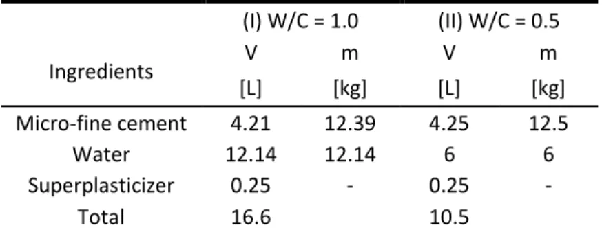
3.3.2 Grout Mixes and Related Properties ... 30
3.3.3 Beam Specimens ... 31
3.3.4 Testing Program ... 31
3.3.5 Modified Modulus of Rupture ASTM C78 ... 32
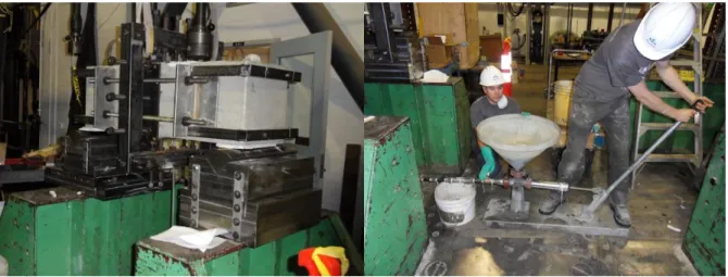
3.3.6 Grouting Repair ... 33
3.3.7 Shear Test ... 34
3.4.1 Mass Concrete Mix and Related Properties ... 35
3.4.2 Grout Mixes and Related Properties ... 36
3.4.3 Modulus of Rupture ... 37
3.4.4 Shear Strength ... 39
3.5 Summary and Conclusions ... 40
3.6 Acknowledgments ... 43
3.7 References ... 44
CHAPTER 4 COMPLEMENTARY RESULTS AND GENERAL DISCUSSION ... 47
4.1 Development of Concrete Mix ... 47
4.2 Grout Rheology ... 53
4.3 Test Method Design ... 54
4.3.1 Direct Tension ... 55
4.3.2 Splitting Test ... 55
4.3.3 Modulus of Rupture ... 56
4.4 Injection Procedure ... 56
4.5 Complementary Load-Displacement Data ... 58
4.5.1 Modulus of Rupture ... 58
4.5.2 Shear Test ... 60
4.6 Prospective Future Work ... 62
4.6.1 Experimental ... 62
4.6.2 Numerical ... 63
CONCLUSIONS ... 65
LIST OF TABLES
Table 2-1: Relationship Between Compressive Strength and Tensile Strength of Concrete ... 8
Table 3-1: Mass Concrete Mixes ... 29
Table 3-2: Grout Mixes ... 30
Table 3-3: Specimens and Test Order ... 32
Table 3-4: Concrete Rheology ... 35
Table 3-5: Concrete Properties ... 36
Table 3-6: Grout Properties and Rheology ... 36
Table 3-7: Modulus of Rupture Test Results ... 38
Table 3-8: Shear Test Results ... 39
Table 4-1: 1967-68 BDJ Concrete Mix ... 47
Table 4-2: Mix1, 2, and 3 ... 48
Table 4-3: Sieve Analysis ... 49
Table 4-4: Small Scale Concrete Mixes ... 50
Table 4-5: Mix A ... 51
Table 4-6: Stacking Model Mixes ... 52
Table 4-7: Wet Concrete Properties ... 52
Table 4-8: Final Experimental Mix ... 53
LIST OF FIGURES
Figure 2-1: Tension Tests: (a) Direct; (b) Brazilian; (c) Modulus of Rupture; (d) Wedge Splitting
... 7
Figure 2-2: (a) Unstable Grout vs. (b) Stable Grout ... 14
Figure 2-3: Grout Intensity Number and Injection flow paths ... 20
Figure 2-4: Grouting of plunging crack: (a) BDJ dam, (b) typical concrete crack pattern, (c) reservoir level, (d) seepage Arch 5-6 ... 23
Figure 3-1: Grouting of plunging crack: (a) BDJ dam, (b) typical concrete crack pattern, (c) reservoir level, (d) seepage Arch 5-6 ... 27
Figure 3-2: Mass concrete cylindrical specimen (400mm x 800mm) ... 29
Figure 3-3:Modified Modulus of Rupture – ASTM C 78 ... 31
Figure 3-4: Injection and Injection Frame ... 33
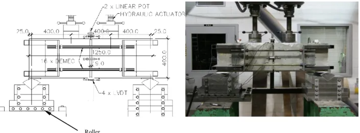
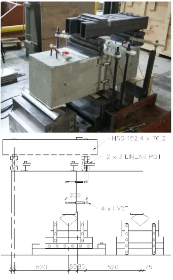
Figure 3-5: Shear Test Setup: (a) Test Setup; (b) Shear Force and Bending Moment Diagram ... 34
Figure 3-6: Modulus of Rupture Failure Plane (Specimen E) ... 37
Figure 3-7: Force vs. Displacement of Virgin Specimens (A to F) ... 38
Figure 3-8: Force vs. Displacement of Repaired Specimens (A (grout w/c) and B (grout w/c) .... 38
Figure 3-9: Shear Failure Plane: (a) vertical failure plane – Specimen B; (b) inclined failure plane – Specimen D ... 40
Figure 4-1: Granulometric Curve ... 49
Figure 4-2: 28 Day fc` (small scale mix) ... 50
Figure 4-3: Grout-Rheological tests: (a) Bleeding, (b) Cone Marsh, (c) Thermocouple ... 53
Figure 4-4: Typical Thermocouple Results ... 54
Figure 4-5: Injection: (a) Injection Flow Path, (b) Injection Frame ... 57
Figure 4-6: Modulus of Rupture Instrumentation ... 58
Figure 4-8: Shear Test Instrumentation ... 60 Figure 4-9: Load vs. Deformation: (a) Crack Opening B, (b) Center Deflection B, (c) Overhang
B, (d) Crack Opening D, (e) Center Deflection D, (f) Overhang D ... 61 Figure 4-10: Potential Future Shear Test with Normal Force ... 62 Figure 4-11: Potential Future Bi and Tri Axial Test ... 63
LIST OF ACRONYMS AND ABBREVIATIONS
Acronyms
ACI American Concrete Institute ASTM American Standard Test Method GIN Grout Intensity Number
ICOLD International Committee on Large Dams RTCG Real Time Control Grouting
UDEC Universal Distinct Element Code
Abbreviations
BDJ Daniel-Johnson Dam
LP Linear Potentiometer
LVDT Linear Variable Displacement Transducer
LIST OF SYMBOLS
A Shear Area
c Conversion Constant OR Cohesion
fc Compressive Stress
fr Third Point Bending Tensile Test Tension Stress (Modulus of Rupture) fsp Splitting Tensile Test Tension Stress (Brazilian)
ft Direct Tensile Test Tension Stress
N Normal Force
μ Coefficient of Friction
τ Shear Stress
INTRODUCTION
Hydroelectric concrete dams are large complicated mass concrete structures that are prone to cracking. It is essential that the proper upkeep be done so that these structures are kept and maintained in safe working order. To this end, the cracks that are formed in dams must be repaired. Many different types of repair technics exist; however, injection grouting is the most common form of dam crack repair. The study of grout injection has mainly focused on, to date, the injection grout used in repairs: rheology, cured properties such as compressive and tensile strengths, and on the distribution and penetrability of the grout during an injection. Although injection grouting has been taking place for many years, there is still little research on the mechanical tensile and shear strengths of repaired sections of mass concrete.
Research Problem
To date, the best way to ascertain the quality of a grout injection repair in a dam is by taking a core of the repaired concrete. In the case of dam mass concrete, this may prove problematic. The first problem is that it is not always possible or convenient to obtain a core of the repaired section of dam. Additionally, given the size of the aggregates used, it would not be possible to take a core which is large enough in diameter to determine the actual strength of the repaired section (ASTM, 2002c).
This problem exists with all repaired mass concrete structures. For the purpose of this research, it was decided to focus the study on a successful repair of a crack network of a single arch of a multiple arch dam.
The Daniel-Johnson Dam (BDJ) located in the Manicouagan River in Quebec, Canada, is the largest multiple arch dam in the world. The 214 m tall dam consists of 13 cylindrical arches being supported by 14 buttresses, with a crest length of 1300m (Tahmazian, Yeh, & Paul, 1989).
Shortly after construction, many different types of cracks developed in the dam. The Dam underwent many grout repair campaigns to minimize seepage and to remove uplift pressure. Of particular interest is the repair of the plunging cracks in the arch 5-6 of the dam. The repairs undertaken proved successful in stopping virtually all the seepage in the arch. The problem is that, although the cracks are repaired, to date there is no information on tensile and shear strength that these repairs provide. Because of this lack of information, the numerical models developed to
predict the structural stability for different reservoir elevation (including Flood) assume that the grouted cracked zone provides no tensile or shear strength. This leads to a potential loss in maximum volume reservoir capacity (Saleh et al., 2003).
Goal and Objectives
The main goal of this experimental research is to determine the mechanical resistance of a section of mass concrete that has been repaired by grout injection. A focus was put on trying to replicate the repairs seen in the 5-6 arch of BDJ.
To this end, the following objectives were established:
Develop a mass concrete mix that is representative of the BDJ concrete (maximum aggregate size of 150 mm & compressive resistance of 33MPa) (Bulota, Im, & Larivière, 1991);
Develop an experimental setup capable of determining the tensile stress of mass concrete and grouted mass concrete specimens (400 x 400 x 1200 mm);
Develop an experimental setup capable of determining the shear resistance of grouted mass concrete specimens (400 x 400 x 1200 mm);
Develop an experimental setup capable of injecting repair grout to the failure plane and maintaining the grout under a constant pressure until it has cured;
Quantify the tensile resistance of an un-cracked specimen, a specimen repaired with stable grout (w/c = 0.5), and a specimen repaired with unstable grout (w/c = 1.0);
Quantify the shear resistance of a specimen repaired with stable grout (w/c = 0.5) and unstable grout (1.0);
Quantify the effects of multiple repairs on tensile resistance and shear resistance;
Use the results obtained to make recommendations on the residual resistance of repaired concrete in both tension and shear.
The following chapter will describe the general approach taken for this experimental research and will define the organisation of the thesis
CHAPTER 1
APPROACH TO THE PROJECT AND ORGANIZATION
OF THE THESIS
The previous chapter identified the research problem and the objectives. The approach taken in the project to meet these objectives is described in this chapter.
1.1 Approach to the Project
Initially, the first step is data acquisition. To this end, a liaison with Hydro-Quebec was needed. The communications that took place served to gather information on the history of the Daniel-Johnson dam, the cracks that occurred, and the repair methods that have been used. Detailed injection plans and injections reports were acquired. Moreover, ideas on the relevant information needed and on research plans were exchanged. The communications with Hydro-Quebec were a constant throughout the course of the project.
An extensive literature review was done to determine what has been done on this front so far. The literature review covered, mass concrete, causes for cracking in dams (thermal stress, chemical attacks, hydrostatic overload), the types of cracks seen, and repair methods used. It then examines grout properties (both liquid and cured) such as viscosity and compressive strength. The previous research on grout injection in general and specifically on mass concrete dams was reviewed and discussed. Lastly, three case studies of grout injections for dam repairs were overviewed.
To complete the objectives, the first step was to determine a facility capable and willing to produce our mass concrete mix. In tandem with the development of the mix, the testing methods to obtain the tensile and shear strengths were developed and a testing protocol was established. Once completed, the specimens were tested and the data obtained was analysed.
The results and main conclusions can be found in Chapter 3 a technical paper that was written and submitted to American Concrete Institute Structural Journal in November 2012.
1.2 Organisation of the Thesis
This thesis starts with an introduction, which briefly describes the subject and highlights the issues that need further attention. Chapter 1 is a transitory summary of the approach taken for the project as well as the organisation of the memoire. Chapter 2 presents an extensive literature
review. Chapter 3 is the paper entitled “Mechanical Resistance of Cracked Dam Mass Concrete Repaired by Grouting: an Experimental Study” which was submitted to ACI. Chapter 4 is comprised of complimentary data not found in the article as well as some general discussion. A conclusion on the project follows can be found after Chapter 4.
CHAPTER 2
LITERATURE REVIEW
The objective of this research project is to evaluate the effectiveness of grout injection repairs to cracks in unreinforced concrete dams. More specifically, it is to evaluate the tensile strength and shear strength of a repair done with microfine cement grout with water to cement (w/c) ratio of 0.5 and 1.0. Determining the effects of multiple repairs was also a consideration. To be able to properly draw any conclusions from any experimental study it was important to first understand the elements discussed in the literature review. The first element discussed is mass concrete, what it is, its different properties, and how those properties are tested. The mechanics of dam cracking and dam crack repair are then addressed. Injection repairs, and the injection materials are then examined in detail. Finally three case studies dams repaired by grout injection are reviewed: Isle Maligne gravity dam (43 m), Sayano-Shushenskoe dam (242 m), and Daniel-Johnson multiple-arch Dam (215 m).
2.1 Mass Concrete
Mass concrete is considered to be concrete that is cast in place in such large volumes that special precautions need to be taken to control excessive temperatures and the effect that these temperatures will have on the final cured concrete. Generally mass concrete has larger than average aggregate sizes including crushed rock. The maximum aggregates usually vary between 80 mm and 150 mm although it is possible to use smaller or larger maximum aggregate sizes. Moderate-heat or low-heat cement, with additives and admixtures to control temperature are typically used for dam construction (ACI-Committee-207, 1970).
The compressive strength of dam mass concrete can range from 20 MPa to 40 MPa after 90 days. The modulus of elasticity of concrete dams at 90 days is typically found to be between 30 and 45 GPa. Poisson‟s ratio for mass concrete normally varies between 0.15 and 0.25 (ACI-Committee-207, 1970).
2.1.1 Compressive Strength
The compressive strength of dam concrete is its most important property, since in dam design a great effort is put into minimizing tension and promoting stress through compression. Typically,
rapid high compressive resistance, except in certain cases, is not required for dams (ICOLD-Committee-on-Concrete-Dams, 2008).
The main element that controls tensile resistance in mass concrete is the porosity of the cement paste, which depends on the water/cement (w/c) ratio. The weakest link in concrete, and the initial cracking point, is at the interface between the aggregate and the cement matrix and the porosity at this point is what affects the strength. Because porosity is not easily measured, the w/c ratio is normally used. Lowering the w/c ratio in mass concrete will typically improve the properties of the concrete that are important for dam construction such as strength and impermeability (ICOLD-Committee-on-Concrete-Dams, 2008).
The type of aggregate, its strength, and the maximum aggregate size also play an important role in the strength of mass concrete. Typically, the strength of mass concrete is increased with increasing aggregate size. This trend can be reversed if large quantities of cement are used in the concrete mix. Additionally, as mentioned by Nallathambi, Karihaloo, and Heaton (1985), the critical energy release rate is also increased by increasing maximum aggregate size. As the aggregate strength is increased, the concrete mix using that aggregate will also show increased strength. The type of aggregate used can have varying effects on the strength of the concrete. The amount of water absorption of different rocks will have an effect on the w/c ratio used in a mix. For proper workability, certain sands also require a larger w/c ratio, which in turn has a negative effect on strength. Additionally, the cohesion between the cement matrix and different aggregates plays a role on concrete strength. This could be affected by the presence of dust on the aggregates. Lastly, the roughness of the aggregates will have an effect on the interlock found between the aggregates, which will also affect the concrete strength (ACI-Committee-207, 1970; ICOLD-Committee-on-Concrete-Dams, 2008).
The different admixtures and additives used in the concrete mix will also affect the compressive strength of the concrete mix.
It was found by Khaloo, Shooreh, and Askari (2009) that when testing mass concrete specimens, the 7 day tests are unreliable. It was also noted that the maximum aggregate size does not have a size effect factor on the test results if sufficiently large test specimens are chosen. Larger test specimens, however, tend to have lower compressive strengths.
2.1.2 Tensile Strength
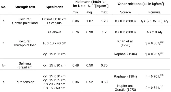
The tensile strength of concrete dams is an important factor in determining dam safety. According to Raphael (1984), the tensile resistance of concrete is a constant property; however, the resistance measured varies depending on the method used to quantify it. The three most commonly used tests to determine tensile strength are as follows: direct tensile test, ft; splitting tensile test (Brazilian), fsp; and third point bending test (modulus of rupture), fr. Much work has been done to determine the relationship between these different tensile strengths and the compressive strength of concrete. These relationships can be found in Table 2-1. The stress states caused in the specimens during the different tests can be seen in Figure 2-1 (ICOLD-Committee-on-Concrete-Dams, 2008).
The direct tensile test method is the least accurate of the 3 methods and shows the widest variation, as seen in the work done by Nianxiang and Wenyan (1989). This is because a small eccentricity in the application of the tensile force can dramatically affect the stresses in the specimen. Additionally, surface drying decreases the observed tensile strength dramatically for this test (Raphael, 1984).
(b) (d)
(c) (a)
Not to scale
The splitting tensile test provides the tensile strength value that is the most accurate and representative of the actual tensile strength according to Raphael (1984). For this test the effects of surface drying are negligible because, as can be seen from Figure 2-1, there are large compressive forces at the surface of the specimen, where surface drying is important, and the tension plane is located within the specimen (Raphael, 1984).
The third point loading test tends to give results that are closest to the results found in numerical modeling, which are inclined to overestimate stresses. This is due to the fact that this test model assumes, until rupture, a constant modulus of elasticity for the complete stress-strain curve. This method has less variability in results than the other two methods and the results from this test are easily reproducible (Raphael, 1984).
A fourth recently developed test method, the wedge splitting test, is advantageous because it allows for the strain softening portion of the stress-strain curve to be obtained and thus allows the fracture energy to be calculated (ICOLD-Committee-on-Concrete-Dams, 2008; Nordtest, 2005).
Table 2-1: Relationship Between Compressive Strength and Tensile Strength of Concrete
No. Strength test Specimens
Heilmann (1969) 'c' in: fi = c · fc2/3 [kg/cm2]
Other relations (all in kg/cm2)
min. avg. max. Source Formula
fr Flexural:
Center-point load
Prisms H: 10 cm
L: various 0.86 1.07 1.28 ICOLD (2008) fr = (2.5 to 3.0).Afc
fr
Flexural: Third-point load
As above 0.76 0.98 1.2 ICOLD (2008) fr = 2.0.Afc
10 x 10 x 40 cm Khan et al. (1996) fr = 0.86.fc 2/3 cyl: 15 x 53 cm Raphael (1984) fr = 0.95.fc2/3 fsp Splitting (Brazilian) cyl: 15 x 30 cm 0.48 0.50 0.70 ft Pure tension cyl: 15 x 30 cm cyl: 15 x 25 cm 5 x 20 x 20 cm 9 x 15 x 60 cm 0.36 0.52 0.68 Raphael (1984) ft = 0.70.fc2/3 Kupfer and Gerstle (1973) ft = 0.64.fc 2/3 Note: 10kg/cm2 = 1 MPa; If f
c is input in MPa, multiple fi by 0.464 for approximate value in MPa.
2.1.3 Shear Strength
The shear strength for mass concrete can be represented by the following formula:
Where:
= Shear Strength = Cohesion
= Shear Area
= Coefficient of Friction [tan ( ). = Friction Angle] = Normal Force
The first part of the equation represents the bond between the different elements on the shear plane. It is a material property that is affected by the component of the concrete mix. The second part of the equation is simply the resistance due to friction. It is dependent on the normal force applied to the shear plane and the rugosity of the shear plane. With larger aggregates, there is better interlock between aggregates and a larger rugosity is observed on the shear plane leading to a higher shear resistance (ICOLD-Committee-on-Concrete-Dams, 2008).
The shear strength of concrete is most important when evaluating discontinuities in a dam, such as joints and cracks. On average, shear strength of mass concrete is found to be roughly 0.2 times its compressive strength, for concretes with maximum aggregate size of 38 mm (ICOLD-Committee-on-Concrete-Dams, 2008).
The fracture energy for shear tests was found by Bažant and Pfeiffer (1986) to be roughly 25 times larger than for tensile failures. This is thought to be due to the interlocking that takes place between aggregates during shear failures, which is more important than for tensile failures. This is a reason why maximum aggregate size and surface roughness is very important in shear strength (Chupanit & Roesler, 2008).
2.1.4 Multi-Axial Stress States
It was found by Wang and Song (2009) that the compression and tension resistance of mass concrete is stronger under uniaxial forces than under biaxial compression-tension or tri-axial
compression-tension-tension. They also proposed equations for the failure criterion of mass concrete under these multi-axial stress-states.
2.1.5 Modulus of Elasticity and Poisson’s Ratio
The modulus of elasticity and Poisson‟s ratio for mass concrete are again affected by the w/c ratio, aggregates, admixtures, and additives.
As with the strength of concrete, a decrease in w/c ratio will increase the modulus of elasticity and Poisson‟s ratio. When the strength of concrete increases, so does the modulus of elasticity; however, they are not directly proportional. Additionally, the modulus of elasticity of the aggregate used also plays an important role in the modulus of the mass concrete.
There is a wide variation found in the measured Poisson‟s ratio and modulus of elasticity of mass concrete. This is attributed to the fact that it is difficult to accurately measure the different displacements on a large heterogeneous mass concrete specimen (ACI-Committee-207, 1970).
2.1.6 Additional Considerations
Shah and Kishen (2010) note that in concrete-concrete cold joints, the size effect rules, a set of equations developed to account the effect of size on specimen strength (a larger specimen will have a lower strength), developed by Bažant (1999) still hold. Additionally, it was found that the greater the difference between the concretes on either side of the cold joint, the weaker the cold joint becomes and the more brittle the failure of the specimen.
2.2 Cracking in Concrete Dams
2.2.1 Causes
The main reason of cracking in concrete dams is due to tensile stresses in unreinforced concrete that exceeds the tensile resistance of concrete. There are many causes for the stress states that lead to the deterioration and cracking of concrete. The most important in concrete dams are temperature changes and large temperature gradients, chemical reactions, hydrostatic overload, and hydrofracturing (Lapointe, 1997; Saleh et al., 2003; Veltrop, Yeh, & Paul, 1990).
2.2.1.1 Thermal Stresses
Changes in temperature in any material will create a change in volume. If this material is not free to move, this volume change will create stresses. Thermal stresses in mass concrete are typically seen for two reasons: because of seasonal temperature cycles and because of heat released from cement hydration. Since the hydration of cement is necessary, it is not possible to avoid this heat; however, there are ways to mitigate it or counter-balance it. Normally the concrete mixes used for mass concrete have much less cement per unit volume then standard structural concrete, which reduces the amount of heat created. There are many additives and admixtures that can be used to delay or reduce the heat of hydration. It is also possible to use ice in place of water when mixing the concrete to decrease the differential between the ambient temperature and the final cured temperature of the concrete. Another technique commonly used is to pass cooling pipes throughout the concrete to help dissipate the heat created. Slight temperature changes can be acceptable; however, any large temperature change will create cracking in the dam. Seasonal changes in ambient temperature are not avoidable but their effects on the main mass of a concrete dam are not felt as much as on the surface. Generally, the cracking caused by seasonal temperature cycles will be on the surface of the structure and will not penetrate deeply into the dam (ACI-Committee-207, 1970; Lapointe, 1997).
2.2.1.2 Chemical Attacks
The most common chemical reaction in concrete is the alkali-silica reaction, which is caused by the reactions between the hydroxyl ions in the water and the silica in the aggregate. This happens when a reactive aggregate is chosen and leads to expansion in concrete. This change in volume leads to tensile stresses that in turn might lead to cracking. Many other types of chemical deterioration can take place in a dam, but they are all caused by a change in volume and the stresses that this change causes (Lapointe, 1997).
2.2.1.3 Hydrofracture During Grouting
Hydrofracture during the grouting of dams initiates when the pressures in the injection fluid cause stresses in the concrete that exceed the maximum allowable tensile stress of the dam concrete. When evaluating the stresses, it is important to consider both the pre-existing stresses in
the structure as well as the stresses caused by the injection (Saleh et al., 2003; Wong & Farmer, 1973).
2.2.1.4 Hydrostatic Overload
Hydrostatic overload can be caused by poor designs such as disjointedness in geometry, the structure not acting monolithically or as was intended, or due to flooding. Since every dam is unique, having different soil conditions, topographic setting, climatic conditions, and available construction materials, it is very difficult to identify all the potential problems that may arise. That is why it is often very difficult to identify the cause or causes of cracks in dams (Veltrop et al., 1990).
2.2.2 Types of Cracks in Dams
There are many different types of cracks in dams. They can be horizontal or vertical, thin or thick, have a large or small area, or be any combination of the aforementioned qualities. It is often necessary to do an in-depth investigation to determine the nature of a crack. There are many methods used to characterize and map a crack. Cameras can be lowered down boreholes to visually inspect the crack or ultrasound can be used to ascertain the extent of the cracks. Cores taken from the concrete can be tested for mechanical strength and used in chemical and petrographic tests to evaluate the quality of the concrete (Jansen, 1988; Lapointe, 1997). New methods such as the use of Rayleigh waves to characterize cracks and evaluate repairs, as proposed by Aggelis, Shiotani, and Polyzos (2009) and the method of using air-coupled sensors to evaluate crack depth, as proposed by Kee and Zhu (2010) are constantly being developed and put into practice.
2.2.3 Repair Methods
Cracks in dams can cause many problems including hindering the structural integrity of the structure, problems with leakage, aesthetic concerns, and durability issues. There exists many ways of repairing cracks. Depending on the nature of the crack and the reason for the repair, the most efficient repair method is chosen. Some of the methods are stitching, drypacking, post-tensioning, and grout injection. Stitching consist in connecting both sides of the crack with „U‟ shaped steel pieces. This repair method can only be used if the crack mouth is accessible. It does
not close cracks; it only provides tensile resistance to the crack area. This repair may cause stress concentrations and therefore cracking at other locations in the structure. Drypacking consists in filling a crack with a low w/c ratio mortar and hand-tapping it into place. This technique is appropriate for dormant cracks and for shallow or aesthetic cracks. Post-tensioning consists in drilling holes through the cracks, inserting post-tension rods through the holes and then filling the holes with grout. This repair method will close an open crack and will provide very good resistance. It is important however to provide sufficient anchorage to the bars for risk of causing eccentricities and tensile forces leading to cracking at other locations in the structure. Because of this constraint, this repair method is usually not suitable for the repairs of cracks in most dams. By far the most common repair method for cracks in concrete dams is grout injection (ACI-Committee-224, 1984; United-States-Dept-of-the-Army, 1970).
2.3 Injection
2.3.1 Injection Grout Properties
Grouts have two sets of properties: their rheological properties, before curing, and their hardened properties, once cured. The important rheological properties for injection grouts are their density, stability, granulometry, penetrability, curing time, cohesion, and viscosity. Once cured, the important characteristics are grout density, mechanical resistance, adhesion, chemical resistance, shrinkage, expansion, and resistance to erosion (Mnif, 1997).
2.3.1.1 Stability
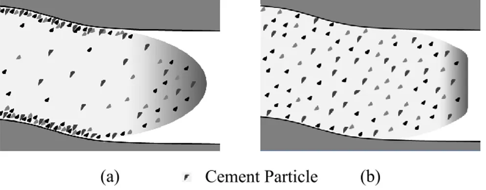
Grout stability is one of the most important characteristics of an injection grout. The stability of the grout reflects the amount of bleeding that occurs in the grout, or the amount of particle sedimentation. A grout is considered stable if the amount of bleeding is less than 5% after 2 hours of being at rest (ASTM, 2003). A stable grout will have little bleeding while an unstable grout will be prone to bleeding and sedimentation, as seen in Figure 2-2. Additionally, the stable grout will be more viscous than the unstable grout. The easiest way to affect the stability in a cement based grout is to modify the w/c ratio (G. Lombardi, 1985b).
2.3.1.2 W/C Ratio
The w/c ratio is an important variable in cement grouts. A minimum w/c ratio is required to ensure the hydration of all cement particles. As the w/c ratio is increased beyond this point, capillary porosity is increased, leading to weaker cured grout. A low w/c ratio will yield a stable grout having a large density and viscosity before curing and to a cured grout with larger resistances and better cohesion and adhesion. Although a stable grout will yield a cured grout of higher quality, the increased viscosity decreases its injectability. A low w/c ratio will require larger injection pressures to ensure that it propagates through the crack network. To increase injectability, a higher w/c ratio is required (Axelsson, Gustafson, & Fransson, 2009). It has been observed that in cases with an excessive w/c ratio, the cement hydration takes place with individual grains without forming a grout matrix. This results in a fine powder of hydrated cement particles on the bottom surface of the crack. Stability and the w/c ratio of injection grouts are essential in achieving a balance between injectability of the grout and the quality of the cured grout (Giovanni Lombardi, 2007).
Additionally, the w/c ratio has an effect on the strength of the cured grout. As in concrete, a lower w/c ratio leads to a stronger grout. In fact, it was found that in certain grout mixtures, the w/c ratio is the most important factor affecting grout strength (Chen, Ye, & Zhang, 2009).
2.3.1.3 Viscosity and Cohesion
The viscosity and cohesion of a grout are determined from flow time, which can be determined by the use of a Marsh cone (ASTM, 2004b). The viscosity of a fluid, measured in Poise, is a
(a) Cement Particle (b)
measurement of its internal shear strength. An injection grout with a low viscosity will require smaller injection pressures to deform the fluid and thus to properly penetrate a crack. When a fluid with a large viscosity is being pumped, a much larger force is required to deform the fluid. The cohesion of a fluid is a measurement of the shear force needed to put the fluid in motion. The larger the cohesion of a fluid, the larger the injection pressure required to push the fluid a given distance. Both viscosity and cohesion are closely related properties (Deere & Lombardi, 1985; G. Lombardi, 1985a).
2.3.1.4 Leaching
When injecting, it is often into a crack filled with water. Because of this, it is important that the grout can resist being washed away by the water and that it does not leach into the water, or mix with the water. The use of a stable grout helps tremendously with the anti-leaching capability of the grout. Studies done by Dumont (1997) found that the use of colloidal admixtures can help greatly with the grouts ability to resist leaching; however, depending on the w/c ratio of the grout, they may not be appropriate since they reduce injectability. It is often necessary to use superplasticizers with the colloidal agents to ensure injectability.
2.3.1.5 Thixotropy
Thixotropic fluids are fluids that have a relatively large viscosity when they are static, but when agitated, become less viscous. This is an important property of some chemical injection grouts. It can be advantageous because during the injection or pumping of the grout, it has a decreased viscosity that allows for better penetration and injectability. Once the injection process stops, the grout becomes more viscous. This limits the amount of grout that moves out of place or is eroded during the curing process (Mnif, 1997).
2.3.1.6 Maximum Grain Size
The maximum aggregate size coupled with the injection pressure will determine the minimum crack width that can successfully be injected. The rule of thumb is that the maximum grain size must be at least 3 times smaller than a crack to ensure that no blockage occurs (Axelsson et al., 2009). However it was found by Draganović and Stille (2011) that penetrability can be reduced if too small a grain size is used. This can be attributed to smaller grain sizes having faster hydration
times and larger attraction occurring between particles. This leads to flocculation which can in turn block the flow path.
2.3.1.7 Curing Time
The set time for injection grouts needs to be well controlled. It is important that the grout does not set before it can properly penetrate the crack being injected. If however the set time is too long, there is a risk of the injection grout being washed out or in cold temperature, freezing (Giovanni Lombardi, 2007).
2.3.1.8 Temperature
The temperature of the injected medium is of import for grouting. Heat is a necessary part of the chemical reactions that take place during the hydration of cement-based grouts and during the chemical reactions that take place in chemical grouts. To keep grouts warm in cold climates and ensure proper curing, it is possible to use external heat sources and use accelerators to decrease setting time and increase hydration heat (Biggar & Sego, 1990; Zhivoderov, 1993).
2.3.2 Types of Grout
There exists a variety of injection grouts including clay grouts, asphalt grouts, chemical grouts, and cement grouts. New injection materials are always being developed (Argal, Korolev, Kudrin, & Ashikhmen, 2009). An infinite number of different grout properties can be obtained by modifying the components and ratios of these components in a grout mix. For the injection of cracks in concrete dams, the most commonly used are chemical or cement-based grouts (Domone, 1993).
2.3.2.1 Chemical Grouts
There are wide varieties of chemical grouts available on the market, the most common types being silicate acrylate, lignin, urethane, and epoxy grouts. The most common type of chemical injection grout used for the purpose of crack repair in concrete dams is epoxy-based grouts. Epoxy grouts are typically two separate organic chemicals that are mixed prior to being injected. By modifying the components used, it is possible to obtain epoxy grouts with varying rheological and structural properties so as to be able to obtain the best grout for any given injection. There have been some concerns regarding the proper curing of epoxy grouts at low temperatures since
some degree of heat is required to start the chemical reaction between the two components. However recent developments with epoxy grouts have yielded positive results with the injection repair of cracks at near freezing temperatures (Chertykov & Dzhuraev, 1983; Privileggi, 2012). Another concern with epoxy grouts is that their material properties vary greatly from that of the base material, or mass concrete. For best results in a repair, it is beneficial if the modulus of elasticity of the repair material is roughly equal to that of the base material, but for epoxy, this is usually not the case (Chandra Kishen & Rao, 2007; Morgan, 1996; Rio, Fernandez, & Gonzalo, 2006).
2.3.2.2 Cement Grouts
By far, the most common injection grouts used for dam repair are cement-based injection grouts. Cement-based grout consists of cement powder mixed with water and different admixtures and additives. Cement is a finely ground powder with a diameter ranging from a few microns to 50 μm. Once water is mixed with the cement, an exothermic chemical reaction called hydration occurs. This reaction leads to the hardening of the grout (Domone, 1993; Saleh, Tremblay, & Desbiens, 1997).
2.3.3 Additives and Admixtures
There are wide ranges of additives and admixtures that can be incorporated into grout mixes to modify the fluid characteristics and set characteristics of injection grouts. Additives include slag, silica fume, fly-ash, pozzolans, and bentonite to name a few. They are added to the cement powder for the purpose of creating strength gains, enhancing chemical resistance, delaying set time or hydration, increasing cohesion and viscosity, reducing bleeding, and as filler material. Admixtures are added to the grout during the mixing phase and include water-reducing (plasticizers), air entertaining, corrosion resisting, set-retarding, and accelerating admixtures (Naudts, Landry, Hooey, & Naudts, 2003).
Accelerators increase the rate at which hydration occurs, they can be useful in cases where important leakages through cracks could disturb the grout before it can properly set. Retarders, on the other hand, are used to slow down the rate of hydration in situations where there is a long delay between mixing the grout and its injection. The simplest way of increasing the injectability of a grout is to increase the w/c ratio. However, as previously discussed, this will decrease the
strength of the hardened grout and decrease the bond between the grout and the injected medium. For this reasons, high-range water reducers or superplasticizers are almost always used for grout injections. Superplasticizers are chemicals that prevent the particles in the grout mix from grouping together, thus decreasing the amount of water required to obtain a stable grout, since clumping and settling of particles is reduced (Naudts et al., 2003).
The effect of the composition of grouts on its rheological behaviour has been widely studied. Many relationships have been developed to predict grout rheology based on the grout mixes (Nguyen, Remond, & Gallias, 2011). Various studies on the effects of particular grout additives have been done. For example it was found by Bremen (1997) that the use of bentonite greatly reduces penetrability of grout mixes and that if penetrability is of import, the use of bentonite should be minimized and the addition of superplasticizers increased. Tests done by Khayat, Yahia, and Sayed (2008) underline the effects of various admixtures and additives on the fluidity, rheology, stability, and compressive strength of grouts. Most notably, it was found that proper dispersion of the agents is important to the final product. The addition of superplasticizers greatly enhances stability and increases grout strength.
2.3.4 Injection Methods
Grout injection is not a definitive science; it is constantly being improved and studied. There exist many different schools of thought on grout injection, such as the classical injection method, the GIN method, and the RODUR method. The basic approach to all of these dam crack injection methods is to drill multiple holes to the crack and to pump an injection grout into the holes in succession. Depending on the method and the crack, different parameters will be measured in real time to determine the progress of the injection, if any injection parameter needs to be modified (grout mix, pressure, etc.), or if the injection should be stopped (Bruce & De Porcellinis, 1989; Giovanni Lombardi, 1998).
A maximum pressure is set for most injections. This maximum is to ensure that the pressure in the crack does not become such that it will cause crack propagation.
The first step with any injection method is to first investigate the cracks. That is to determine the history of the crack, the cause of the crack, whether the crack is active or stable, the flow in the crack, and any other information that may be useful. The next step is to establish an injection
method and its features: the number of injection holes that will be required, injection hole spacing, injection grout properties, injection pressures, real-time measurements, etc. This is why every injection campaign uses a different and unique approach (G. Lombardi, 1997).
As more and more is being understood about grout propagation and grout behaviour, new grouting methods are always being developed, such as the RTCG method by Stille, Gustafson, and Hassler (2012), and the methods discussed by Pronina and Ashikhmen (1996).
2.3.4.1 Classical Injection Method
This injection method consists of starting the injection process with a grout with a high w/c ratio. As the injection progresses, the w/c ratio of the injection grout is gradually decreased to a specified ideal value. The assumption is that if a low w/c ratio grout is used, the crack will not be filled properly without risk of crack propagation. If, on the other hand, a high w/c ratio grout is used, the quality of the repair will be poor due to the excess water and bleeding. The idea behind this method is that the high w/c ratio grout will be able to penetrate the crack completely. Although the quality of the grout is not ideal, the particles should settle and form a grout layer throughout the entire crack. As the grout w/c ratio is reduced, the quality of the repair should increase. The w/c ratio is gradually decreased until either the injection pressure reaches the pre-specified maximum or until the w/c ratio of the grout reaches its lower limit. This injection method is the most common repair method and has served successfully in countless repair campaigns; however much research has been done suggesting that it is not the most efficient grouting strategy (Giovanni Lombardi, 1998).
2.3.4.2 GIN
GIN stands for Grout Intensity Number and is represented as a curve on the injection pressure vs. volume curve as seen in Figure 2-3. The GIN method uses a single grout mix for the entire injection. This grout must be stable (w/c ratio between 0.67 and 0.8 by mass), a low-to-medium injection rate must be used, and real-time measurements of pressure and injected volume must be taken. The injection of each individual hole is stopped once the GIN line is intersected on the pressure vs. volume graph (G. Lombardi & Deere, 1993).
2.3.4.3 RODUR
The RODUR injection method uses chemical epoxy resin grouts as opposed to cement-based grouts. The grout used for every repair is developed based on the needs of each situation; however, there are some properties that are always desired. The grout must be a true Bingham fluid, must be immiscible in water, and must have a constant and predictable viscosity until set. The RODUR method relies on a single injection at each location. Additionally, crack propagation is not a huge constraint with the RODUR method. This is because the crack is injected in sections so that the entirety of the crack is not subjected to large uplift pressures simultaneously. It is assumed that the portion of the dam not being injected can compensate for the uplift pressure caused at the injection location. It is assumed that the injected pressure decreases very rapidly from the point of injection which further limits the risk of crack propagation. Lastly, if the crack does propagate, it is assumed that it will simultaneously be filled with the grout and repaired (Bruce & De Porcellinis, 1989).
2.3.5 Addition Considerations
Javanmardi and Léger (2005) developed a simplified method considering nonlinear finite element of concrete cracking, hydromechanical coupled analysis, grout state change analysis, and hardened grout in the repair to adequately model the grouting process. It was also shown that the Universal Distinct Element Code software could successfully be used to model the grouting process (UDEC, 2000).
2.4 Repair Case Studies
2.4.1 Isle Maligne Hydroelectric Power Complex
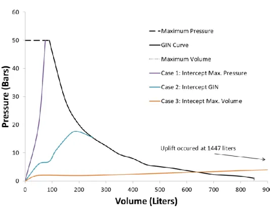
The Isle Maligne Hydro Electric complex is located in Lac St-Jean, Alma, Quebec, Canada. Local lift joints in the left gravity dam abutment (43 m high by 110 m long) of the dam were repaired by grout injection using the GIN method. The maximum allowable pressure was first selected based on the crack opening, cohesion of the concrete, weight of the concrete, and pre-stressed anchor load. The maximum injection volume was then determined using the maximum pressure, the crack thickness and the concrete cohesion. By multiplying these two numbers (maximum pressure and maximum volume), a GIN value is established. A GIN number was calculated for each section to be injected. The GIN curve (pressure vs. volume) is plotted for each injection point and during the injection, the flow path is plotted on the same graph in real-time. Once it intersects the GIN curve, the grouting is stopped. On Figure 2-3, a sample GIN curve and three (3) observed grouting paths are plotted. Case 1 represents the injection being stopped because the injection pressure reached the specified limit. In this case, no uplift was observed even though the injection pressure was very high. This is due to the fact that the volume of injection grout is small and exerts this pressure over a very small area. Case 2 represents the injection being stopped when the injection path reached the GIN curve. Case 3 represents the case where the crack accepted large volumes of grout with minimal increase in pressure. For this case, the injection was continued past the maximum allowable volume for experimental purposes. It was observed that after exceeding the volume limit, small uplift was observed with no increase to the pressure. At this point, the injection was stopped and the uplift was reversed. This result indicates that there is a risk of uplift even at low pressures. When this pressure is exerted over a large area, uplift can be seen. Except for the case were the injection path was in excess of the
GIN curve (experimental case 3), no uplift was observed (Turcotte, Savard, Lombardi, & Jobin, 1994).
2.4.2 Sayano-Shushenskoe Hydrostation Dam
The Sayano-Shushenskoe Dam, on the Yenisei River in Khakassia, Russia, is a gravity arch dam with a height of 242 m and length of 1074 m. The water stops and grout curtain proved to be unsuccessful, leading to cracking near the base of the upstream side of the dam and lifting between the dam and bedrock. Once the dam was filled to normal usage levels in 1996, water seepage over a 15 m area near the base of the dam was measured to be 458 liters per second. In 1991, an injection campaign using the classical injection method was undertaken to stop the leakage. Due to the high flow rates in the cracks and the interconnectivity between the cracks, the horizontal drainage holes, cooling pipes, and the investigation bore holes, these repairs proved to be unsuccessful. The injection grout was simply washed out. Many ineffective or failed attempts were made until 1995 when two alternate approaches were attempted. The first using the roflex material (polymer elastic) and the second using the RODUR method. The attempts made with the roflex material failed because the roflex material loses its penetrability at low temperatures and becomes overly viscous. The RODUR injection grout used had high viscosity, good penetrability, low surface tension, and rapid set times at low temperatures. The injections proved successful and completely stopped seepage in the injected section of the dam. Due to this success, an injection campaign to repair the entirety of the seepage was started. Forty injection zones were identified but due to financial constraints, and to the assumption that the compression caused by the injection of some zones would benefit others, 24 injection zones where settled upon. The injection grout used was injected with a pressure varying from 25 to 40 MPa along 15 to 20 m-long injection paths. Due to the length of the path and the viscous nature of the grout, the pressure at the crack mouth was found to vary between 6 MPa and 8 MPa. Extensometers were installed to monitor the movement of the cracks during the injection and an additional crack opening of 2.5 mm was used as a stop criterion for injection. These injections did cause adjacent non-repaired cracks to open further; however, cracks previously repaired did not generally open due to the compression created by their repairs. The repair was successful with only 1% of the seepage remaining in the injected zones (Bryzgalov et al., 1998).
2.4.3 Daniel-Johnson Multiple-Arch Dam
Located on the Manicouagan River north of Baie-Comeau in Quebec, Canada, the Daniel-Johnson Dam is the largest multiple arch dam in the world. It has a crest length of 1300 m, a height of 215 m, and a reservoir area of 2000 km2,which translates into 140x109 m3 of water. The dam consists of 13 cylindrical arches being supported by 14 buttresses (Saleh et al., 2003).
Shortly after its construction which started in 1962 and ended in 1968, the Daniel-Johnson Dam (BDJ) experienced multiple types of cracks and infiltration (Saleh et al., 2002).
Debonding at the base of the dam in most arches was detected due to seepage observed at the base of the structure [Figure 2-4 (b)]. The seepage was stopped by grout injections (Bulota et al., 1991).
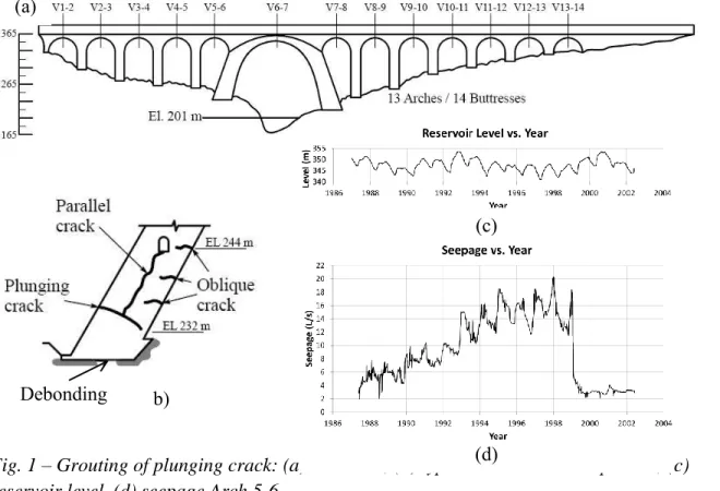
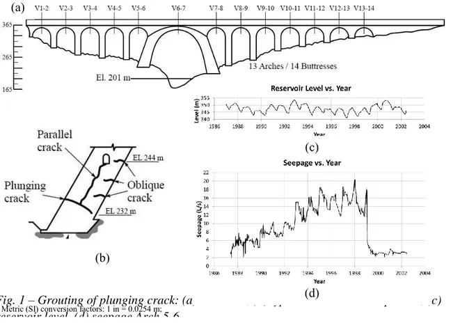
Figure 2-4: Grouting of plunging crack: (a) BDJ dam, (b) typical concrete crack pattern, (c) reservoir level, (d) seepage Arch 5-6
Fig. 1 – Grouting of plunging crack: (a) BDJ dam, (b) typical concrete crack pattern, (c) reservoir level, (d) seepage Arch 5-6.
(c) (a)
(d) (b)
Oblique cracks as seen in Figure 2-4 (b) on the downstream side of the dam were first observed in 1969. These cracks, which are due to thermal stresses, start off being horizontal and form elliptical arcs while moving towards the buttresses. These cracks were generally perpendicular to the downstream face of the dam and on average went to a depth of 35% of the thickness of the dam. Thermal shelters were put in place at the base of the downstream side of the dam to stop the crack propagation (Bulota et al., 1991; Tahmazian et al., 1989).
Plunging cracks, seen in Figure 2-4(b), were caused by a lack of compression in the base of the arches (Larivière, Routhier, Roy, Saleh, & Tremblay, 1999). These plunging cracks initiated in the center of the arches near the upstream foundation of the dam, to then travel horizontally and start diving towards the downstream foundation of the structure (Veltrop et al., 1990).
An injection campaign aimed at repairing these cracks was started in 1969 and ended in 1982 after a moratorium was put on grout injections due to the hydraulic fracturing caused by significant injection pressures using unstable grout with high w/c ratios. After the repairs, the seepage rate increased at a constant rate of roughly 1 l/s per year until 1992, when the seepage rate suddenly increased by 5 l/s in five weeks. A team was put in place to study the problem and in 1997 a grout injection operation was undertaken to repair the plunging crack in arch 5-6 of BDJ using micro fine cement grout [maximum grain size of 12m (0.472 mils)] (Saleh et al., 2003).
The classical injection method was selected, starting with a grout with a w/c ratio of 1.0 and gradually decreasing it until the stop criteria were met. The stop criteria included a maximum injection pressure of 0.2 MPa above the uplift pressure in the crack and a limited injection area of 100 m2 (Hydro-Quebec, 2008).
The injection campaign was successful with virtually all of the seepage through the arch having been stopped (Saleh et al., 2003).
2.5 Conclusion
Grout injection repairs of dams depend on many factors discussed in this literature review. The properties and composition of the mass concrete being repaired, the properties and composition of the injection grout being used, as well as the specific injection method being used all play an important role in grout injections for dam crack repair. There is still much research and debate
surrounding grouting repairs; however, the material presented in this literature review sets a good foundation for the understanding of the process and sets a starting point for the material presented in Chapter 3.
Although the repairs for BDJ were successful in stopping nearly the entirety of the seepage, it is not known whether this repair actually provides any tensile or shear resistance to the structure. For this reason, it is assumed in numerical models that the tensile resistance for the repaired area is null. As will be presented in Chapter 3 there is reason to believe that this assumption may be overly conservative. The following chapter presents the experimental research done on ascertaining the tensile and shear strengths that the injection for BDJ provided.
CHAPTER 3
ARTICLE 1: MECHANICAL RESISTANCE OF
CRACKED DAM MASS CONCRETE REPAIRED BY GROUTING: AN
EXPERIMENTAL STUDY
3.1 Introduction
Concrete dams are structures that are prone to cracking. Shrinkage, large temperature gradients, and hydrostatic overload are just some of the causes of cracking in dams. Shortly after its construction, the Daniel Johnson Dam (BDJ) experienced multiple types of cracks including plunging cracks which were caused by a lack of compression in the base of the arches.1,2 These plunging cracks initiated in the center of the arches near the upstream foundation of the dam, then travel horizontally and start to dive towards the downstream foundation of the structure (Figure 3-1 a). To minimize water infiltration and leakage as well as to improve structural integrity by eliminating uplift pressures, these crack needed to be repaired.
There are various methods of repair techniques ranging from post-tensioning to injections following different procedures and using different materials. In the case of BDJ and for similar types of cracks, the most common repair method is grout injection.3
An injection campaign aimed at repairing these cracks was started in 1969 and ended in 1982 after a moratorium was put on grout injections due to the hydraulic fracturing caused by significant injection pressure using unstable grout with high water cement (w/c) ratio.4 Since, many repair products including epoxy based grouts, and micro fine cement grouts have been studied and tested.5,6,7,8 In 1997 a grout injection operation was undertaken to repair the plunging crack in arch 5-6 of BDJ using stable micro fine cement grout [maximum grain size of 12mm (0.472 mils)]. From Figure 3-1, after the injection operation, the total water leakage from arch 5-6 and buttresses decreased from roughly 19 L/s (1159.5 in3/s) to 3 L/s (183.1 in3/s). The repair is important not only to decrease leakage but also to remove uplift pressures that the water in the cracks creates.1,4
Since the injection, as can be seen from Figure 3-1, the water level in the reservoir has increased to above pre-repair levels without having a noticeable effect on water leakage. These results suggest that the repair increases the ability of the crack mouth in BDJ to sustain tensile stresses post-injection. In the finite element models used to assess the initiation and propagation of
grouted crack it is most often assumed that there is no gain in mechanical strength because little data exists on the strength a repair may provide in mass concrete.9
Injection grout research is well documented in terms of rheology, composition, and injectability.10,11 There have been some studies done on the tensile strength of mass concrete and on cold jointed concrete, however the strength of a repaired section of mass concrete has yet to be studied.12,13,14 In the work presented here, the tensile and shear resistance of mass concrete and repaired mass concrete was investigated experimentally following a modified ASTM C78 test procedure and a shear test procedure.15 Results from virgin specimens, repaired with an injection grout with a water cement ratio of 1.0 (Grout I) and of 0.5 (Grout II), were compared. This research provides experimental failure behaviour and resistances of mass concrete and the related grouted cracks under flexural loading and shear loading.
Metric (SI) conversion factors: 1 in = 0.0254 m;
Fig. 1 – Grouting of plunging crack: (a) BDJ dam, (b) typical concrete crack pattern, (c) reservoir level, (d) seepage Arch 5-6.
(c) (a)
(d) (b)
Figure 3-1: Grouting of plunging crack: (a) BDJ dam, (b) typical concrete crack pattern, (c) reservoir level, (d) seepage Arch 5-6
3.2 Research Significance
Many studies have been undertaken on the repairs of dams as well as on various different injection grouts and repair methods, however there is little literature or experimental research on the mechanical strength of repaired sections of concrete, especially mass concrete. This experimental study is useful in determining the modulus of rupture and shear strength of repaired mass concrete while not having to account for the scaling factor of the aggregate size. This study also provides valuable experimental data to assign mechanical strength in numerical models of repaired dams including grouted cracks.
3.3 Experimental Investigation
3.3.1 Mass Concrete Mix and Related Properties
The initial BDJ concrete mix used 150 mm (6 in.) max size aggregate. To properly account for the rugosity of the large aggregates, but given the constraints of the laboratory, maximum aggregates of 100 mm (4 in.) were selected for the experimental concrete mix. All specimens tested were from the same concrete mix; three batches were needed to pour all six prismatic beam specimens used [400 x 400 x 1250 mm (16 x 16 x 49.2 in.)]. The maximum aggregate size was 100 mm (4 in.) or 2/3 the max aggregate used for BDJ. Due to the large maximum aggregate size, the minimum dimension of a given specimen could not be smaller than 300 mm (12 in.);16 400 mm (16 in.) was chosen to be conservative. The following are the components of the mix which can be found in Table 3-1: General Use Portland cement (Low Heat cement was not used because it has little effect on the strength and would increase cure time), superplasticizer (to increase workability), entrained air, well graded siliceous river sand, and well graded limestone aggregate. The mix was developed by modifying the original 1967-68 mix of BDJ while keeping similar granulometry and composition and to have a compressive strength of 30 MPa (4.35 ksi), roughly the initial compressive strength of BDJ, while making the concrete workable.7
Table 3-1: Mass Concrete Mixes
1967-68 BDJ Mix Final Experimental Concrete Mix
Material 1000 L Material 1000 L
Cement** 234 kg Cement 270 kg
Large Sand 364 kg Sand 675 kg
Fine Sand 363 kg Aggregate 20-10 148 kg Aggregate 5-10 305 kg Aggregate 38-20 231 kg Aggregate 10-20 220 kg Aggregate 75-38 445 kg Aggregate 20-40 345 kg Aggregate 150-75 534 kg Aggregate 50-100 450 kg Water*** 113 kg Water 143 kg Entrained air 770 ml
Entrained air 0.3 kg Superplasticizer 3090/2730* ml
* Batch 2 and 3, ** LH, ***Frozen (Ice) Note: 1 kg = 2.20lb, 1L = 61.02in3, 1ml =0.06102in3
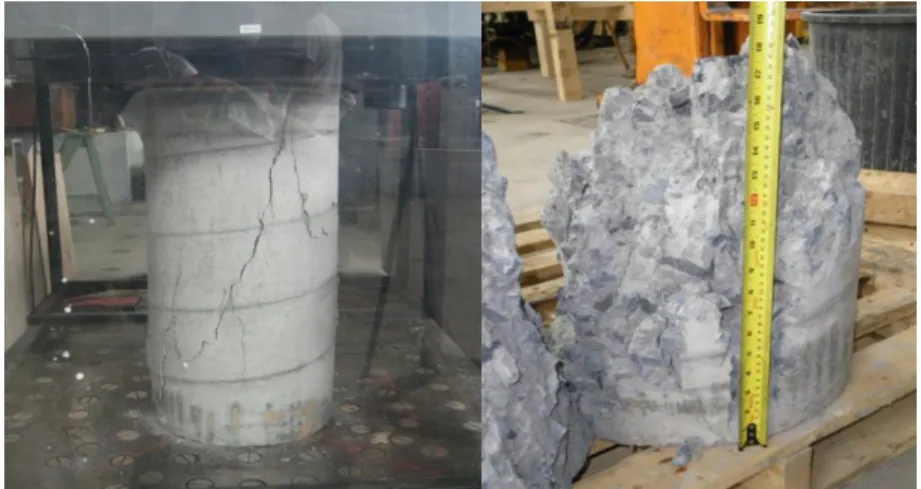
Three cylinder specimens, seen in Figure 3-2, of 400 mm (16 in.) diameter and 800 mm (32 in.) in height, one from each batch of concrete, were poured into cardboard tubes. A modified version of ASTM C469 (to account for the larger specimens) was used to determine the compressive strength, modulus of elasticity, and Poisson‟s ratio of the concrete.17 The size effect for the results of the compressive strength are negligible.18