UNIVERSITÉ DE MONTRÉAL
CUTTING CONDITIONS OPTIMISATION OF TITANIUM METAL MATRIX COMPOSITES IN TURNING AND FACE MILLING
ALIREZA ASGARI
DÉPARTEMENT DE GÉNIE MÉCANIQUE
ÉCOLE POLYTECHNIQUE DE MONTRÉAL
MÉMOIRE PRÉSENTÉ EN VUE DE L’OBTENTION
DU DIPLÔME DE MAÎTRISE ÈS SCIENCES APPLIQUÉES
(GÉNIE MÉCANIQUE)
DÉCEMBRE 2015
ÉCOLE POLYTECHNIQUE DE MONTRÉAL
Ce mémoire intitulé :
CUTTING CONDITIONS OPTIMISATION OF TITANIUM METAL MATRIX COMPOSITES IN TURNING AND FACE MILLING
présenté par: ASGARI Alireza
en vue de l’obtention du diplôme de : Maîtrise ès sciences appliquées
a été dûment accepté par le jury d’examen constitué de :
M. VADEAN Aurelian, Doctorat, président
M. BALAZINSKI Marek, Doctorat ès sciences, membre et directeur de recherche
DEDICATION
ACKNOWLEDGEMENTS
I would like to express my sincere gratitude to my advisor, Professor Marek Balazinski, for the opportunity he has given me to work at the “laboratoire de recherché en fabrication virtuelle (LRFV) 'of École Polytechnique de Montréal.” Without his thrust, guidance, patience and supports, my research would not have been successful. Undoubtedly, he was the most influential person during my M.Sc. and I hope the bond that we established will continue for many years to come.
My immense appreciation extends to Professor Aurelian Vadean and Professor René Mayer serving as members of jury of my M.Sc. defense committee and for providing valuable comments.
I appreciate National Sciences and Engineering Research Council of Canada (NSERC) Innovation in Machining Technology (CANRIMT) for their financial supports.
Sincere thanks are extended to Dr. Seyed Ali Niknam for the time and efforts he spent to edit and improve my thesis.
Special thanks go to manufacturing laboratory technicians, Mr. Guy Gironne and Mr. Vincent Mayer for their excellent cooperation.
I really appreciate Mrs. Martine Bénard and Mrs. Carole Fraser for all the helps.
I wish to give my wholehearted thanks to my parents for their unwavering supports, kind words, well-wishing and patience for abiding by my absence. Special thanks go to my beloved wife Shilla and my children Anahita and Jasmine for their patience and for burden of life during the final stages of this thesis.
RÉSUMÉ
Il y a quelques décennies, les industries ont utilisé les composites à matrice métallique de titane (Ti-MMC) dans les valeurs limitées. Chacune des industries s'intéresse à la caractéristique particulière du Ti-MMC. Les constructeurs de voitures s'intéressent à la résistance à l'usure et à la fatigue de ce matériau dans la fabrication des composantes de moteur et de transmission pour ainsi diminuer le poids des véhicules. Les fournisseurs d'accessoires et de matériel médicaux utilisent le Ti-MMC vu sa grande rigidité spécifique et sa résistance en compression élevée. De plus, dans les domaines aéronautique et aérospatiale, les fabricants sont intéressés par le gain en légèreté de ce matériau.
Mais il y a un problème avec le Ti-MMC, il a une faible usinabilité. Les aspects importants et acceptables pour l'usinage de pièces en industrie sont le coût de fabrication, de la finition de la surface et de la conformité au devis. Aussi, une dureté augmentée par les particules de céramique et une rigidité élevée du produit induisent un facteur de propagation élevée de fissures dans le corps du Ti-MMC. De plus, les particules fissurées ont tendance à éroder les arêtes des outils de coupe provoquant la dégradation de la finition de surface. Une très faible conductivité thermique, une haute résistance à la compression et une basse tendance à la déformation plastique devant l'arête de l’outil de coupe lors de son engagement avec ce matériau portent les contraintes mécaniques et thermiques à augmenter durant le processus d'usinage.
Il n’y a que peu d’études sur le Ti-MMC, en particulier sur l'usinage de ce matériau. En général, les outils PCD sont connus comme étant les outils les plus performants lors de l'usinage du MMC, mais le coût de production est fortement affecté par le prix élevé de ces outils. Cette étude fait suite à des expériences réalisées sur l'effet de trois sortes d'outils (carbure revêtu, PCBN et PCD) sur le tournage et (carbure et d'outils PCD) sur le surfaçage du Ti-MMC. Sur les conséquences de la productivité, le taux d'usure des outils et la rugosité de surface de la pièce. Les conditions de coupe optimales sont déterminées pour chaque outil au tournage et au fraisage en bout du Ti-MMC. Les effets des paramètres de coupe sont extraits par analyse de variance. Pour l'optimisation du processus de tournage et de fraisage avec chaque outil, la méthode Taguchi est utilisée. De plus, les données de performance de ces outils lors de ces expériences sont analysées.
ABSTRACT
World leading manufacturing sectors, in particular aerospace and automotive industries wish to have lighter materials with better physical, mechanical and chemical properties than the prevalent hard to cut heavier materials. This has brought much attention to alternative materials such as metal matrix composite (MMC). MMCs are composed of non-metallic reinforcements (i.e. ceramic) in metal matrices which feature high toughness, wear and fatigue resistance and relatively light weight. One of the metallic composite with remarkable mechanical properties is titanium metal matrix composite (Ti-MMC). Ti-MMC has been successfully incorporated into numerous of products in various industrial sectors. Each industrial sector has an interest in particular characteristics of Ti-MMC. Automotive and aerospace industries are craving for high wear and fatigue resistant materials with low weight for delicate applications in engine and power train component. Medical components suppliers utilize Ti-MMC in pursuance of its great specific stiffness and elevated compressive strength.
Despite having excellent features, various issues have emerged relate to the machining and machinability of Ti-MMCs. Due to the presence of hard and abrasive ceramic particles in metal matrices of Ti-MMCs, crack propagation appears on the Ti-MMC body. Furthermore, weak heat conductivity, low tendency to plastic deformation and high compressive resistance of the matrix exert large mechanical and thermal stresses to the cutting tool and the work-piece. This reveals that the principal machinability attributes of Ti-MMCs are rapid tool wear, low surface quality in Ti-MMC machined parts and excessive cost. According to the review of literature, there are few studies on the machining and machinability of Ti-MMCs. There is a lack of knowledge on appropriate setting levels of cutting process parameters for machining Ti-MMC, in particular milling and turning operations that deal with high material removal rate.
The main objectives of this work are to study the cutting parameters governing the tool wear and surface quality (finish) when machining (milling and turning) Ti-MMCs, as well as cutting factors optimization using Taguchi method to better reach the optimum or near optimum surface finish, tool wear and productivity. To that end, comprehensive experimental studies are arranged in multi-level full factorial design and orthogonal array design of experiment.
TABLE OF CONTENTS
DEDICATION ... III ACKNOWLEDGEMENTS ... IV RÉSUMÉ ... V ABSTRACT ... VI TABLE OF CONTENTS ... VII LIST OF TABLES ... IX LIST OF FIGURES ... XI LIST OF SYMBOLS AND ABBREVIATIONS... XIV LIST OF APPENDICES ... XVI
CHAP TER 1 INTRODUCTION ... 1
1.1. PROBLEM STATEMENT ... 2
1.2. OBJECTIVE ... 2
1.3. SCIENTIFIC HYPOTHESES ... 3
1.4. ORIGINALITY ASPECTS AND INDUSTRIAL BENEFITS ... 3
1.5. THESIS STRUCTURE ... 3
CHAP TER 2 LITERATURE REVIEW ... 5
2.1. INTRODUCTION ... 5
2.2. TITANIUM METAL MATRIX COMPOSITES (TI-MMC) ... 5
2.3. CUTTING PROCESS ... 11
2.4. CUTTING TOOLS ... 15
2.5. CUTTING FLUIDES ... 21
2.6. DESIGN OF THE EXPERIMENT ... 22
2.7. METHOD OF ANALYZE OF VARIANCE (ANOVA) ... 24
2.8. OPTIMISATION METHODS ... 27
CHAP TER 3 METHODOLOGY ... 33
3.1. INTRODUCTION ... 33 3.2. EXPERIMENTAL PLAN ... 33 3.3. METHOD OF ANALYSIS ... 34 3.4. OPTIMIZATION METHOD ... 34 3.5. CUTTING TOOLS ... 37 3.6. INSERTS ... 39
3.7. WORK-PIECE MATERIAL ... 42
3.9. SUPPORTING TOOLS AND STRATEGY ... 45
CHAP TER 4 TURNING EXPERIMENTS AND RESULTS ... 51
4.1. EXPERIMENTAL PLAN ... 51
4.2. TURNING EXPERIMENTS ... 51
4.3. RESULTS AND DISCUSSION ... 54
4.4. ANALYZING THE TOOLS WEAR DURING THE EXPERIMENTS ... 66
CHAP TER 5 MILLING EXPERIMENTS AND RESULTS ... 69
5.1. EXPERIMENTAL PLAN ... 69
5.2. MILLING EXPERIMENTS ... 69
5.3. RESULTS AND DISCUSSION ... 72
CHAP TER 6 CONCLUSION AND RECOMMENDATIONS ... 84
BIBLIOGRAPHY ... 86
LIST OF TABLES
Table 2-1: Mechanical and thermal properties (Konig 1978) ... 9
Table 2-2: The properties of the cutting tools materials(Heath 1986) ... 16
Table 3-1: Experimental parameters in machining Ti-MMCs ... 34
Table 3-2: Effects of individual levels of experimental parameters ... 35
Table 3-3: SNR within each level of the experimental parameters ... 36
Table 3-4: Relative Standard Deviation of each Level Signal Power from the Strongest Signal .. 36
Table 3-5: Characteristics of the coated carbide insert for turning tests (SECO) ... 39
Table 3-6: The composition of the carbide inserts (Kennametal) ... 40
Table 3-7: Characteristics of the coated carbide insets (Kennametal) ... 40
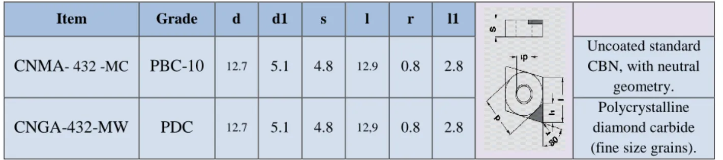
Table 3-8: Characteristics of PCBN and PCD inserts used in turning (Becker) ... 42
Table 3-9: Characteristics of PCD inserts used in milling (BECKER) ... 42
Table 3-10: Specification of MAZAK Nexus 200 (https://www.mazakusa.com) ... 43
Table 3-11: MITSUI SEIKI 5-AxisModel HU40T (http://www.mitsuiseiki.com) ... 44
Table 3-12: Specification of the Kistler dynamometer used ... 46
Table 3-13: Specification of the Kistler dynamometer used ... 46
Table 3-14: Specifications of the profilometer (Mitutoyo SV-C4000) used ... 47
Table 4-1: Orthogonal array L27(313) ... 52
Table 4-2: Cutting conditions used in turning with carbide inserts ... 52
Table 4-3: Orthogonal array L9(34) ... 53
Table 4-4: Cutting conditions and responses in turning with CBN inserts ... 53
Table 4-5: Cutting conditions in turning with PCD inserts ... 54
Table 4-6: ANOVA table of results recorded in turning by carbide inserts ... 55
Table 4-8: Cutting force results for turning with carbide inserts ... 58
Table 4-9: Final results of optimized cutting conditions for the turning carbide inserts ... 61
Table 4-10: ANOVA table of results recorded in turning by CBN inserts ... 62
Table 4-11: Surface roughness and tool wear rate ... 62
Table 4-12: Comparing mean of results and productivities ... 63
Table 4-13: Final results of optimized cutting conditions for the turning CBN ... 65
Table 4-14: Turning tests with PCD inserts having elevated tool wear ... 66
Table 5-1: The cutting conditions used in face ... 70
Table 5-2: Milling experimental plan ... 71
Table 5-3: Cutting parameters in milling with X500 insert ... 71
Table 5-4: Cutting parameters and the responses ... 72
Table 5-5: ANOVA of the surface roughness and tool wear rate with carbide (X-500) ... 73
Table 5-6: Surface roughness and tool wear rate values of carbide X-500 inserts ... 73
Table 5-7: Final results of optimized cutting conditions for the milling by X-500 inserts ... 76
Table 5-8: ANOVA of the tool wear and the surface roughness of the work-pieces ... 77
Table 5-9: Results of the surface roughness and wear rate for PCD inserts during milling ... 77
Table 5-10: Final results of optimized cutting conditions for the milling by PCD inserts ... 80
Table 5-11: The wear on the carbide insert X400when used in milling ... 80
LIST OF FIGURES
Figure 2-1: The strength to specific ratio of highly used metals (Hurless and Froes 2002) ... 7
Figure 2-2: A race car’s gearbox case (left), Hip implant (middle) and Bicycle frame (right) ... 8
Figure 2-3: Ti-MMC parts under high pressure and temperature conditions in the car engine ... 8
Figure 2-4: The cutting tool and its related wearing type ... 10
Figure 2-5: Heat distribution along the ... 11
Figure 2-6: Relationship between cutting speed and cutting temperature ... 12
Figure 2-7: Energy cycle during cutting process (Klocke and Kuchle 2011) ... 13
Figure 2-8: Temperature and hardness in various cutting ... 17
Figure 2-9: Various modes of wear on the tool’s faces ... 19
Figure 2-10: Tool wear mechanisms ... 20
Figure 2-11: Statistical distribution of a response(Woodcock 1997) ... 26
Figure 2-11: Taguchi loss function (Heizer and Render 1991) ... 28
Figure 3-2: The curvature of the noises and their effects ... 35
Figure 3-3: Two kinds of interaction amongst the controllable parameters ... 30
Figure 3-4: Turning tool holder used inthe experiment ... 37
Figure 3-5: Milling tool and carbide insert X500 (Kennametal) ... 38
Figure 3-6: Milling tool and carbide insert X400 (Kennametal) ... 38
Figure 3-7: Milling cutter with PCD inserts (BECKER) ... 39
Figure 3-8: The CNC turning center MAZAK Nexus 200 ... 43
Figure 3-9: MITSUI SEIKI 5-Axis- Model HU40T (http://www.mitsuiseiki.com) ... 44
Figure 3-10: Kistler dynamometer for Turning ... 45
Figure 3-11: Kistler dynamometer for milling ... 46
Figure 3-13: Optic Microscope (Olympus SZ-X12) ... 48
Figure 3-14: Camera setup ... 49
Figure 3-15: First adjustment of the camera ... 50
Figure 3-16: Alignment of the lights: (1) and (2) are the LCD lightening arms, ... 50
Figure 4-1: Experimental plan flowchart ... 51
Figure 4-2: Work surface roughness & Tool wear rate ... 56
Figure 4-3: Cutting forces vs. cutting conditions for turning with carbide inserts ... 58
Figure 4-4: SNRs of cutting related forces (Fx, Fy, Fz) ... 60
Figure 4-5: SNRs of tool wear rate and work surface roughness ... 60
Figure 4-6: RSDs of tool wears and surface roughness signal to noise ... 61
Figure 4-7: Work surface roughness & Tool wear rate vs. cutting conditions for CBN ... 63
Figure 4-8: SNRs of tool wear rate and work surface roughness ... 64
Figure 4-9: RSDs of tool wears and surface roughness signal to noise ... 65
Figure 4-10: Carbide insert after turning Ti-MMC under following cutting conditions ... 67
Figure 4-11: Chipping on the PCD insert... 67
Figure 4-12: Flank wear of PCD inserts ... 67
Figure 4-13: Flank wear of CBN insert under ... 67
Figure 4-14: Flank wear of CBN insert ... 68
Figure 4-15: (Left) CBN insert and related chip; (Right) Carbide insert with adhered material ... 68
Figure 5-1: Trajectory of milling tool (Cutter) on the milling ... 69
Figure 5-2: Lubricated face milling with carbide inserts ... 70
Figure 5-3: Work surface roughness & Tool wear rate vs. cutting conditions ... 74
Figure 5-4: SNRs of tool wear rate and work surface roughness for X-500 ... 75
Figure 5-6: Work surface roughness & Tool wear rate vs. cutting conditions for PCD inserts .... 78
Figure 5-7: SNRs of tool wear rate and work surface roughness for PCD ... 79
Figure 5-8: RSDs of tool wears and surface roughness signal to noise for PCD ... 79
Figure 5-9: Milling Ti-MMC with carbide insert X500 ... 82
Figure 5-10: Milling with carbide insert X400 under following cutting conditions ... 83
Figure 5-11: Edge chipping of the PCD at ... 83
LIST OF SYMBOLS AND ABBREVIATIONS
MMC Metal Matrix Composite
TiC Titanium Carbide
TiN Titanium Nitride
Ti-MMC Titanium Metal Matrix Composite
γwof Fracture-Work
KIc Fracture Toughness
E Modulus of Elasticity
Kr specific Cutting Pressure
ρ Mass Density
UTS Ultimate Tensile Strength
Y Yield Strength BHN Brinell hardness HK Knoop hardness G Shear Modulus τ Shear Strength B Bulk Strength υ Poisson Ratio
C Coefficient of Thermal Expansion
k Heat Conductivity
VB Cutting Tool Flank Wear Width
PCD Polycrystalline Diamond
CBN Cubic Boron Nitride
RSM Response Surface Methodology
Ra Average Surface Roughness
SNR Signal to Noise Ratio
SS Sum of Squares
MS Mean of Squares
ij
y Observed Response
Response Distribution Meanij
Response Residual
TiAlN Titanium Aluminum Nitride
TiSiN Titanium Silicon Nitride
Co Cobalt
Ru Ruthenium
vc Cutting Speed
fr Cutting Feed Rate
ap Cutting Depth
MRR Material Removal Rate
𝑉𝐵𝐵𝑚𝑎𝑥 Maximum Wear of the Straight part of Cutting Edge
LIST OF APPENDICES
CHAPTER 1
INTRODUCTION
With growing the economy, the market demands more reliable and durable products with lightweights and less energy consumption at lower cost. This encourages industrial plants to improve their processes and materials. Significant amount of attentions has been paid to employ in alternative materials to the prevalent heavy materials, such as nickel alloys and steels. Thus, industries are interested in the new materials such as Metal Matrix Composite (MMC), which features high toughness, wear and fatigue resistance and relatively lightweight. One such metallic composite with remarkable mechanical properties is Titanium Metal Matrix Composite (Ti-MMC). It has been introduced to industry as an alternative to Ni-base alloys (Esslinger 1960) and since a few decades, it has been successfully incorporated into a vast number of products in various industrial sectors.
Automotive and aerospace industries typically use Ti-MMC in the rod connections and high wearing comportments. This strategy leads to lower weight and energy consumption in the products. Medical components suppliers employ the Ti-MMC in pursuance of great specific strength (Abkowitz, Abkowitz et al. 2004). The use of Ti-MMC in the thin structures (e.g. bicycle frame) tends to increase the stiffness of the products. Other feature of Ti-MMC, low elongation may help to establish a highly precise and rigid product (i.e. electronic devices). The main obstacle of Ti-MMC utilization is its poor productivity and machinability, which actually increases the machining and production cost. In fact, the hard particles in Ti-MMC generate cracks initiation and propagation in the work body. Moreover, the tool wear and ruining of the surface finish can be resulted.
Due to the above-mentioned difficulties hindering the applications of Ti-MMC, the industrial sectors seeking less expensive operations (e.g. automotive) have shown less interest on further investments on Ti-MMC (Ward-Close, Godfrey et al. 2001). Since 1990s, the automotive industries have had limited contributions in Ti-MMC, particularly in the engine components of sport and luxury cars (Froes, Friedrich et al. 2004). This recalls further investigations on evaluating the machinability of Ti-MMC. In the course of machinability evaluation, several criteria, including cutting force, surface quality and tool performance (wear) are of great importance.
Based on above-mentioned critics raised against the poor machinability and productivity of Ti-MMCs, this work plans to present a comprehensive investigation on the cutting factors governing the tool wear and surface quality (finish) when machining Ti- MMCs. Furthermore, the cutting parameters optimization using Taguchi method is presented to reach an optimum or near optimum surface quality, tool wear and productivity in milling and turning operations.
1.1. Problem Statement
Sever tool wear, short tool life and poor surface finish (quality) are considered the main concerns in machining Ti-MMCs. Due to aforementioned machining concerns, Ti-MMC is grouped as a difficult to cut material that suffer from poor machinability and productivity. Due to the very low thermal conductivity of Ti-MMCs, very high local temperatures are generated in a very small area around the cutting edge that result in high tool wear rate during machining operations. Moreover, oxidation and other chemical wear mechanisms are involved and further reduce the tool life. The performance of each individual tool material (i.e. Polycrystalline Diamond “PCD”, carbide, and Cubic Boron Nitride “CBN”) may vary under different machining operations and cutting parameters. Unfortunately, very limited experimental studies were reported on appropriate selection of tool materials and setting levels of cutting parameters (speed, feed rate) in milling and turning operations to achieve optimum or near optimum tool wear, tool life, surface finish and productivity. No work is reported yet on detailed comparison between the various tools materials used in machining Ti-MMCs. Furthermore, the optimization tools (e.g. Taguchi, GA, RSM) have not yet used to achieve optimum or near optimum tool life or surface finish when machining Ti-MMCs.
1.2. Objective
The main objectives of this work are to present a comprehensive investigation on the cutting parameters governing the tool wear and surface finish when machining Ti-MMCs, as well as cutting parameters optimization using Taguchi method to reach the optimum or near optimum surface finish, tool wear and productivity. In the course of this research project, the following specific objectives are defined:
Understanding the cutting parameters governing the tool wear and surface quality (finish) when machining Ti-MMCs.
Cutting parameters optimization by Taguchi method.
Each above-mentioned objective will be conducted in the case of milling and turning operations.
1.3. Scientific hypotheses
Tool flank wear is the main aspect of tool wear and it will be used as an indicator of the tool wear.
Average surface roughness (Ra) is the best surface quality parameter to specify the quality of the work-piece’s surface finish.
Due to specific mechanical and thermal properties of Ti-MMCs, wet (lubricated) machining is used for the machining of Ti-MMC.
1.4. Originality aspects and industrial benefits
This research project was initiated by the Canadian Network for Research and Innovation in Machining Technology (CANRIMT) and was financially supported by NSERC. The research outcomes can be used by local aerospace and automotive companies, which contributed in this project. This can be considered as the main industrial impacts on the feasibility of the project.
1.5. Thesis structure
This thesis consists of six chapters. It starts with an introduction chapter, followed by a literature review presented in chapter two. Chapter three was devoted to experimental methodology and method of analysis as well as experimental apparatus and materials used in this study. Chapter four and five present the research outcomes and they include comprehensive discussions on the research outcomes. Finally, some conclusions, recommendations and future plans are presented in Chapter 6. The experimental conditions and parameters used in this research work are presented at the beginning of Chapter 4 and Chapter 5.
Chapter 2 presents a comprehensive literature review on various machining operations, machinability aspects of Ti-MMCs including the chip morphology, surface integrity and tooling. This chapter also includes a review of the tool selection for machining Ti-MMCs. Furthermore, an overview of the most widely used optimization methods is presented. This chapter provides
insight into existing research studies, problems and missing links to be addressed. Moreover, this chapter ends with a conclusion of the literature review and a refining of the objectives.
Chapter 3 presents the experimental plan. An overview of Taguchi method as the desired optimization tool is presented. The method of analysis of experimental and optimization results is described. The work material used, along with its composition, mechanical and physical properties are introduced. The implemented tool materials and inserts are described. The CNC machines and other supporting tools including dynamometer, high resolution camera, and profilometer are presented.
Chapters 4 and 5 present the comprehensive experimental studies on evaluating the tool wear mechanisms in PCD, carbide and CBN inserts during turning and milling Ti-MMCs. The effects of each individual tool and cutting process parameter on the surface quality are described. The Taguchi optimization tool is then used to optimize the setting levels of cutting parameters to achieve optimum or near optimum surface quality and tool wear rate in turning and milling operations. Chapters 4 and 5 link the outcomes of this work and the previous studies, and help clarifying certain aspects and shortcomings that were identified in the problematic and research objectives. The discussion also shows the achievements of this research work on improving certain aspects in machining of Ti-MMCs.
CHAPTER 2
LITERATURE REVIEW
2.1. Introduction
This chapter presents the literature review on the features and machinability of Titanium Metal Matrix Composite (Ti-MMC) and studies the existing research works on optimizing the cutting parameters when milling and turning Ti-MMCs.
2.2. Titanium Metal Matrix Composites (Ti-MMC)
The decreased fuel consumption is the most important issue for automotive and aerospace industries to avoid greenhouse gas emission and non-desirable expenses. These could be achieved by decreasing the weight of products and improving the efficiency of engines. Therefore, remarkable materials such as Ti-MMC with exceptional mechanical and physical properties and lightweight can ascertain those requests. Improved compressive strength would resist high loaded stressed on gears, connection rods, bearing and shaft in the engines, turbines and the other similar components. The high temperature resistance of Ti-MMC motivated NASA Glenn research center to examine Ti-MMC reinforced (Box 1953) which is identical to the material used in this study.
The Ti-MMC material, used in this study, was made by Dynamet Technology, Inc. and has been made of Ti-6Al-4V alloy matrix reinforced with 10-12% volume fraction of TiC particles with irregular shapes in 10-20 μm size. The mechanical and thermal properties as well as tribological behaviour of Ti-6Al-4V are enhanced by the ceramic reinforcement (Poletti, Merstallinger et al. 2004). Then, an adequate blend of ceramic and matrix material powders has been exposed to the process of a periodic cold and hot isolated pressing to yield bar stock. Knowing that Ti-MMCs are produced near net shape, finishing is generally required to obtain the adequate surface quality of the work-pieces.
However, these materials suffer from poor machinability due to the hard and abrasive nature of the reinforcing particles, in addition to the low thermal conductivity, low elastic modulus and high chemical reactivity of titanium alloy matrix (Niknam, Khettabi et al. 2014). The following sections present an overview of MMC and TiAl4V.
2.2.1. Metal matrix composite (MMC)
Metal matrix composite (MMC) has an essential base matrix of a light metal such as aluminium, magnesium or titanium. In order to reinforce the structure and enhance the matrix’s tensile and temperature strength (Hunt 1997), 20% ceramic particles; fibres or whiskers are generally dispersed in the metal matrix. Moreover, reinforcement added, the base stiffness and wear resistance of the matrix as well as the fatigue strength at elevated temperature (Kainer 2006) are improved. Nonetheless, MMCs still suffer from poor machinability. In fact, the presence of hard particles, sever tool wear and poor surface finish are considered as the most important drawbacks in the case of machining MMCs.
Abrasion on the tool flank face seems to be the main wear mechanism of all sorts of carbide tool (Muthukrishnan and Davim 2011) used during machining the MMCs, although, adhesion plays the important role on tool wear when using CBN and PCD tools (Ciftci 2009). As observed in (Njuguna, Gao et al. 2013), adhesion on the flank face was the dominant wear mode when using coated and uncoated CBN tools. However, under similar cutting conditions when using PCD tools, less adhesion on the flank face was observed and the rake face chipping was mostly dominant in tool degradation.
Despite the static tests, reinforcements dislocating mechanism in the work-pieces plays different role at high strain rates. When an induced stress exceeds the material resistance limit, further damages propagate as cracks and crush into the reinforced particles. A procrustean stress by developing through the particles cluster creates nucleation and results into material failure. For instance, a crack follows reinforce particles through the cutting direction in turning as-cast aluminium metal matrix composite (Al6061+Al2O3). Indeed, on the voids growing and coalescence, the fracture occurs at a narrow band adjacent the surface (Ganguly, Poole et al. 2001). The reinforcements lead the MMC to yield before high strain appear (Irfan and Prakash 2000). Therefore, plastic deformation of chips abides more dominant on the ductile materials; further, crack propagation plays essential role for the brittle ones.
2.2.2. Ti6Al4V
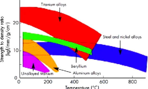
In general, titanium alloys possess higher specific strength among other metals (Figure 2-1) by having around half the specific weight of stainless steel. They have acceptable fatigue strength
and turn not into brittle structure even under -200 C (Hurlich 1968). There are several titanium alloys, used in various industrial sectors. With the light specific weight and aesthetic feature, titanium is an attractive option for the luxury and high class artefacts including jewelleries, golf clubs, eyeglasses, bikes and watches (Taylor and Weidmann 2008). Among titanium alloys, Ti6Al4V inhabits almost 70% of market by having superior strength and lowest elongation percent (Welsch, Boyer et al. 1993). Two phases (α and β phases) of Ti6Al4V structure preserve strong mechanical and thermal properties than that is observed in other alloys at 315°C (Taylor and Weidmann 2008).
Figure 2-1: The strength to specific ratio of highly used metals (Hurless and Froes 2002)
Ti6Al4V has been widely used in prototyping and manufacturing race cars, aerospace products, biomedical components such as implants and prosthesis, marine applications, chemical industries and gas turbines (Leyens and Peters 2003) (Figure 2-2). Low modulus of elasticity and weak wear resistance restrict the applications of Ti-6Al-4V in the connection rods that require strong stiffness and high wear resistance (Ward-Close, Godfrey et al. 2001). Thus, reinforcements (e.g. ceramic particles as TiC) are added into the Ti6Al4V matrix structure to better improve its shortcoming. The TiC particles increase dislocations in the matrix structure. Therefore, the matrix hardness and stiffness are increased while ductility and toughness are decreased. Several delicate
metallic products, including the engine and transmission components endure massive thermal and mechanical stresses. Those comportments should be light to reduce energy consumption (Hurless and Froes 2002). Therefore, Ti-MMC with high specific strengths at elevated temperatures, great wear and corrosion resistances are ideal for those applications.
Figure 2-2: A race car’s gearbox case (left), Hip implant (middle) and Bicycle frame (right) made with Ti-6AI-4V (AB , Taylor and Weidmann 2008)
By improved wear resistance, Ti-MMC can resist high stressed loads on gears, connection rods, bearing and shaft in the engines, turbines and similar components (Figure 2-3).
Figure 2-3: Ti-MMC parts under high pressure and temperature conditions in the car engine (Hurless and Froes 2002)
2.2.3. The machining difficulties of Ti
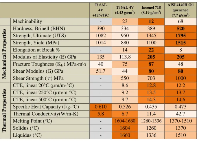
-MMCAs a rule, for a same cutting tool life, a superior machinability allows cutting the related work-piece with higher speed. Table 2-1displays the mechanical and thermal properties of Ti-MMC, Ti6AL4V, Inconel 718 and AISI 4140H. It can be seem that Ti6Al4V has poorer machinability as compared to other materials, except nickel alloy-718.
Low elastic modulus of Ti6Al4V leads to serrated chip formation and cyclic cutting force. Cutting force fluctuation also induces chatter vibration (Antonialli, Diniz et al. 2010) and deteriorates the surface finish and increases the probability of tool failure.
Table 2-1: Mechanical and thermal properties of Ti-MMC, Ti6AL4V, Inconel 718 and AISI 4140H (www.aerospacemetals.com, www.rolledalloys.ca, www.alloywire.com) (Konig 1978)
Ti 6AL 4V +12%TiC Ti 6AL 4V (4.43 g/cm3) Inconel 718 (8.19 g/cm3) AISI 4140H Oil quenched (7.7 g/cm3) Machinability - 23 12 68 M ec h an ical Pr op er tie s Hardness, Brinell (BHN) 390 334 389 520
Strength, Ultimate (UTS) 1082 950 1345 1795
Strength, Yield (MPa) 1014 880 1100 1515
Elongation at Break % - 14 22 8
Modulus of Elasticity (E) GPa 135 113.8 205 205
Fracture Toughness (KIc) MPa-m½ 40 75 87 48
Shear Modulus (G) GPa 51.7 44 80 80
Shear Strength ( ) MPa - 550 703 1000
T h er m al Pr op er ti es CTE, linear 20°C (µm/m-°C) - 8.6 12.8 12.2 CTE, linear 250°C (µm/m-°C) - 9.2 13.5 13.7 CTE, linear 500°C (µm/m-°C) - 9.7 14.3 14.6
Specific Heat Capacity (J/g-°C) 0.610 0.526 0.435 0.473
Thermal Conductivity(W/m-K) 5.8 6.7 11.4 42.7
Melting Point (°C) - 1604-1660 1260-1336 1370-1510
Solidus (°C) - 1604 1260 1370
Liquidus (°C) - 1660 1336 1510
High affinity of almost all tool materials to Ti6Al4V as well as elevated temperature in the tool-work-piece engagement cause the chemical reaction of materials diffusion and adhesion to the cutting tool (Zhu, Zhang et al. 2013). During the cutting process, Ti6Al4V compels the tool tip to
bear roughly 80% of the generated heat. Consequently, even at high material removal rate, the chips cannot evacuate the massive thermal loads (Konig 1978).
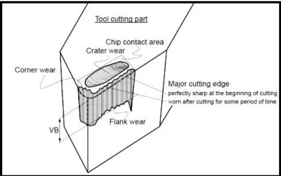
Moreover, at low shear angle (The angle of a plane where work material slips on, to start chip formation), the tool slides than cutting the work-piece (e.g. initial cutting cycles) because of increasing the normal force on the work-piece’s surface; so, the cutting zone temperature and pressure rise (Davim 2012). Then, the scraped materials melt and adhere to the tool tip; the hot adhered particles in the vicinity of oxygen turn into fragments as TiO and V2O3 (Jin, Riahi et al. 2014). Thereafter, the particles on rubbing between the tool and work-piece scratch and furrow the tool surface (Huang and Liang 2004). Schematic view of tool wearing is illustrated in Figure 2-4.
Figure 2-4: The cutting tool and its related wearing type (Fabrication mécanique avancée, Marek Balazinski, École Polytechnique de Montréal, Québec, Canada)
During a cutting process, large strain and high related rate dominate the chip formation. Failure of a ductile materials under high strain rate occurs through an adiabatic shear band (Shear band is a thin band with huge plastic shear strain during dynamic loading) (Zener and Hollomon 1944).
As for brittle materials, (e.g. MMCs), failure happen as nucleation, growth, and coalescence of micro-voids to form a crack (Worswick, Qiang et al. 1992). Furthermore, additional cutting speed surpasses the plastic deformation region and accomplishes to brittle fracture of the chips (Vaughn and Krueck 1960). According to (Recht 1964), machining of brittle materials at high cutting speed reduces the tool vibration and tool wear while high productivity and lower machining cost are expected.
2.3. Cutting Process
2.3.1. Heat Generation during the Cutting Process
One of the main machining phenomena is heat generation in the cutting zone (Figure 2-5). Plastic deformation of the work material as well as friction between cutting tool and work-piece and chips are essential parameters to impel the high thermal loads on a cutting process. High thermal load generally leads to tool degradation and deteriorated surface quality.
Figure 2-5: Heat distribution along the cutting process (Pramanik, Zhang et al. 2008)
At high cutting speed, the strain rate in the shear zone increases; therefore, due to elevated energy, thermal load is intensified. However, according to the work material properties, thermal
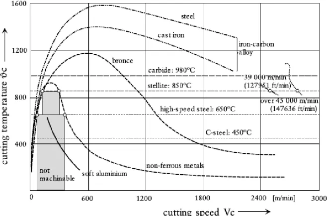
conductivity and strength, the temperature decreases after a certain level of cutting speed(Figure 2-6).Thermal conductivity of a work-piece dominates the temperature elevation rate at the tool tip (Kagnaya, Lazard et al. 2011). Friction is one other parameter to increase rapidly the temperature due to cutting speed. Thus, adding the motion friction to the material deformation increases the cutting heat transferred to the tool-work interface.
Figure 2-6: Relationship between cutting speed and cutting temperature in different materials (Schulz 1999)
High cutting speed increases the cutting zone temperature and deformation strain rate and eventually leads to change in the work-material structure (Thakur, Ramamoorthy et al. 2010). At high cutting speed, the chip dispel the temperature in the cutting zone (King 1985). Aero-engine materials (e.g. nickel and titanium alloys) maintain high toughness and hardness at high temperatures; this feature leads to their poor machinability (Ezugwu, Bonney et al. 2004). The elevated temperatures during machining the aerospace’s materials harden work surfaces and cause higher tool wear and deteriorated surface finish.
Figure 2-7: Energy cycle during cutting process (Klocke and Kuchle 2011)
Two essential phases of titanium alloys structures classified as α with hexagonal closed packed lattice (hcp) which abide up to temperature around 883.5°C and β on body centred cubic (bcc) lattice forming after α up to 1662°C. Both phases display distinctive performances of the plasticity (Kaçal and Yıldırım 2013).
Super-plasticity of Ti6Al4V is extended by growing α phase and the maximum super-plasticity at ratio of α 40% to β phase (Hsiung and Nieh 1997). At super-plasticity temperature, the β phase extends exponentially until complete phase transformation; then after forming the lattice bcc of β phase, the super-plasticity is faded.
However, titanium alloys have poor machinability according to their remarkable resistances to plastic deformation (Lee and Lin 1997). Therefore, the abrasive particle and high resistance to plastic deformation in Ti-MMC constrains high-energy load to the tool-work-piece engagement as shown in Figure 2-7. High cutting energy and temperature cause several problems in the cutting process as:
Reducing the strength, hardness and wear resistance of the cutting tool;
Degrading the dimensional accuracy of the work-piece;
Thermal damage to the machined surface.
2.3.2. Chip formation
The segmented chip formation generally occurs during machining of titanium alloys. During orthogonal cutting of titanium alloy, up to a certain level of cutting speed, localized deformations occur without any segmentation, while at higher speed, localized segmentation tends to appear
(Rokicki, Spotz et al.). During cutting MMCs, reinforcement particles lead the material to resist the plastic deformation and rumpling. Therefore, cutting force may pass the ultimate strength and produces cavities around hard particles in MMC’s soft matrix. The cavities are expanded until they turn into segmented chips (Huang, Zhou et al. 2012).
Lower plastic deformation appears in machining of high strength materials. During high speed milling of Ti-6AI-4V, the increased cutting speed fades the plastic deformation and induces to crack (Du, Chen et al. 2006). However, chip segmentation reduces the cutting force as that observed when having continues chip (Daymi, Boujelbene et al. 2009). In this case, the force fluctuation would appear and consequently deteriorated surface finish results.
During machining Ti-MMC, the cutting force propagates into the matrix along with the reinforcements’ clusters, breaking them and their bonds toward the outer boundary of shear zone. Crack initiation at outer zone of the chip causes segmentation onward the shear zone and the saw-tooth chips formation (Bejjani, Balazinski et al. 2011). It should be noted that cutting at a certain level of ductility proposes the good machinability (Armarego and Brown 1969).
Thicker chips result at increased feed rate and decreased cutting speed and depth of cut (Daymi, Boujelbene et al. 2009). Another important parameter on the chip formation is the work material’s thermal conductivity. Lower heat-transfer from cutting zone decreases the chip thickness. Moreover, the heat left in the cutting zone raises the zone temperature (Sun, Brandt et al. 2009). The ratio of α to β in the structure and the particles dislocations in the α phase have relationship with decreasing the matrix temperature and rising the superplastic deformation (Kim, Kim et al. 1999). Thus, adding the particulate reinforcements in the titanium matrix holds super-plasticity of the matrix at elevated temperature and limits the β grains growing (Lu, Qin et al. 2010).
2.3.3. Cutting force effects
The first general issue on machining MMCs corresponds to the matrix structure that intensifies the cutting force. Whereas, the reinforcement’s hardness, atomic bonding and quantities increase the maximum pressure on the tooltip, friction force as well as the cutting forces fluctuation frequency. Lower levels of cutting speed and higher feed rate decrease the effect of the reinforcements on the tooltip (Gaitonde, Karnik et al. 2008).
One of the machinability criteria known as specific cutting pressure Kr has relationships with uncut chip section area as well as cutting force. Higher levels of Kr tends to degrade the tool wedges (Thakur, Ramamoorthy et al. 2010). Increased cutting speed diminishes the plastic deformation; decreases the Kr (Specific Cutting Pressure) and increases the cutting shear angle. As a result, the effective force on the cutting edge decrease (Daymi, Boujelbene et al. 2009).
During the high speed machining of Al/SiC, in addition to the cutting force, feed force also tends to decrease. Moreover, high feed rate reduces the flank wear and increases the area of heat conduction and heat generation. Higher level of depth of cut in cutting MMC increases the cutting force and flank wear on the carbide tool (Kremer, Devillez et al. 2008).
Disregarding, the matrix properties generate fluctuation of the thrust force (Smith 2008). In the S. Sikder et al study (Sikder and Kishawy 2012), cutting force changed little when strength and hardness of matrix increase from Al6061 to Al7075. However, cutting force depicts more direct relation to the percentage of reinforcements. Furthermore, friction force partakes 20% of the total force in MMC’s cutting process (Das, Behera et al. 2011). If abrasive effect of hard particles in matrix reduces, thereafter, specific cutting force would be decreased by aggressive feed rates and higher cutting speeds (Kremer, Devillez et al. 2008).
2.4. Cutting Tools
The following section presents the most widely used cutting tools in machining Ti-MMCs.
2.4.1. Common conventional tools
There are four types of cutting tool materials as: Carbide
Ceramic (Al2O3/Si3N4)
Cubic Boron Nitride (CBN) high percent
Cubic Boron Nitride (CBN) low percent
Polycrystalline Diamond (PCD)
As shown in Table 2- 2, on one hand PCD displays the greatest hardness between all tool materials; meanwhile its relatively low toughness makes the tool vulnerable to impacts and resulted shocks during cutting force fluctuation. On the other hand, a cutting tool material such as
carbide with high toughness may withstand the impact and force effects; but by having lower hardness, the MMC’s reinforcements scratch and degrade the cutting edge (Stephenson and Agapiou 2005). According to Table 2-2, PCD feature outstanding hardness and incomparable heat conductivities, while ceramic tools are out of range and PCD tools provide the best combination among other tools. Table 2-2 shows the significant toughness of the carbide tool and the highest bulk strength of high percent CBN material.
Table 2-2: The properties of the cutting tools materials(Heath 1986)
Properties WC (k10) Al2O3+TiC CBN (High %) CBN (Low %) PCD (Syndite10)
ρ (g/cm3 ). 14.7 4.28 3.12 4.28 4.12 Y (GPa.) 4.50 4.50 3.80 3.55 7.60 HK (GPa.) 13 17 31.6 27.5 50 KIC (MPa.m½) 10.8 3.31 6.30 3.70 8.80 E (GPa.) 620 370 680 587 776 G (GPa.) 258 160 279 284 363 B (GPa.) 375 232 405 254 301 υ 0.22 0.22 0.22 0.15 0.07 C (10-6/K.) 5.00 7.80 4.90 4.70 4.20 k (W/m K.) 100 16.7 100 44 560
[Ρ (Density), Y (Yield Strength), HK (Knoop Hardness), KIc (Fracture Toughness), E (Elasticity Modulus), G (Shear Modulus), B (Bulk Modulus), υ (Poisson Ratio), C (Coefficient Thermal Expansion), k (Heat Conductivity)]
2.4.2. Cutting tools deficiencies
The friction force and hydrostatic pressure generated during cutting process deform the Ti-MMC and erodes the tool-edge. During machining the high fracture toughness materials (i.e. titanium), cutting speeds variation plays more important role than the feed rate. For instance, during machining Inconel, which has poor machinability, the ceramic tool wears exponentially by gradually increasing the cutting speed. Meanwhile, the feed rate and depth of cut have less effects on the tool degradation rate (Sikder and Kishawy 2012).
Huang et al (Huang, Zhou et al. 2012) studied milling Al-MMC using cemented and PCD tools. It was observed that cutting forces tend to rapidly increase and afterward smoothly mounted up to
flank wear (VB=0.6mm) on the carbide tools. The flank wear was propagated rapidly even at the low cutting speed. However, in the case of PCD tools, cutting forces was gradually increased with an average of about half of that observed in the carbide tool.
The wear in the PCD tool was very rapid at the beginning of the cut, and it became uniform when using vc= 300 m/min. They claimed the reinforced particles could not make micro-cuts on the flank surface of PCD tool. In the other word, the harder tool decreases the force and consequently less tool wear results.
Titanium base components reveal high toughness during cutting process (Froes, Friedrich et al. 2004). CBN tool shows different consequences in cutting the titanium constituents, when the cutting temperature is the most important phenomena.
Figure 2-8: Temperature and hardness in various cutting tool materials (Source: CeramTec)
Further, the cutting speed between 185±22 [m/min] addresses the stable cutting and more appropriate work-surface quality (Zoya and Krishnamurthy 2000). Machining titanium alloys with PCD tools at cutting speed 150 m/min was optimized in (Corduan, Himbart et al. 2003). Zhang et al. (Zhang, Zhou et al. 2013) investigated the effects of vibration on the PCD tool and observed that vibration is one the critical parameters affecting the tool wear.
The cutting tool should possess sufficient strength and hardness at elevated temperatures during machining aerospace materials. Most of the cutting tools lose their hardness and strength at high temperature and experience accelerated wear (Figure 2-8). Aerospace industries utilize coated carbide, CBN, ceramics and PCD tools in machining various materials. Titanium alloys reveal high affinity to the ceramic tools, which hinders their machinability (Kertesz, Pryor et al. 1988).
2.4.3. Tools wear
During the cutting operation, the cutting tool is exposed to various axial and non-axial stresses including the hydrostatic pressure, bending, shearing, vibration and thermal loads, and consequently tool’s material erosion, edge chipping and rusting on the tool wedge generally would be appeared.
Two essential categories that degrade the cutting tool are:
The wear on the tool face due to gradual erosion that tend to increase the cutting forces.
Because of the thermal or mechanical shocks, brutal wears generally appear on the tool. The main features depicted are deformation of the tool tip, cracking and tearing-off a portion of the cutting tool up to complete failure.
The gradual tool wear occurs with three features on the tool faces (Figure 2-9) as:
Crater wear on the rake face
Flank wear on the flank face
Corner wear on the auxiliary flank face near tool nose
When a cutting tool experiences a tangential movement against a work surface, the work-piece embeds hard particles on the tool surface and offensive grooves are generated there. This tool wear mechanism is known as abrasion. Atomic bonding of the work surface’s material and welding to the tool lead to adhesion wear.
Figure 2-9: Various modes of wear on the tool’s faces ("Mechanics of Machining" Lesson-3: Geometry of single point
Cutting tools, Kharagpur.Version 2 ME IIT.)
As a result of high temperature, atoms of the next surface replace and defuse, so the diffusion mechanism occurs on the tool, particularly on the tool rake face as crater wear (Figure 2-10). Vicinity to oxygen at elevated temperature induces different mechanisms which oxidize materials on the tool surface (Klocke and Kuchle 2011).
On the width of the wear ribbon (VB) presented in Figure 2-9, the cutting force elevates to a critical value and deforms or breaks the tooltip. Generally, 0.5 mm of flank wear increases by 90% the feed-force, 100% the passive force and 20% the cutting-force (Klocke and Kuchle 2011). Less machining is expected upon proper modification of productivity and cutting conditions (Kagnaya, Lazard et al. 2011).
Figure 2-10: Tool wear mechanisms
Titanium based materials have poor machinability. High speed steel (HSS) and carbide tools display difficulty to cut those materials over cutting speed range of 30-60 m/min (Hosseini and Kishawy 2014). Polycrystalline diamond (PCD) and Polycrystalline boron nitride (PCBN) depict good performances at high speed machining of titanium alloys (Honghua, Peng et al. 2012).
2.4.4. Surface quality (finish) of Ti-MMC work-piece
During standard milling of Ti-6AI-4V, the average surface roughness Ra is about 6.4 µm, but in high speed milling Ra decreases to 0.8µm, because surface layers wrinkle less than that observed in low speed machining. Higher levels of cutting speed and lower levels of feed rate and depth of cut improve the surface quality and structural integrity of the work-pieces. One of the main surface integrity attributes is residual stress which seems to be generated due to mechanical (plastic deformation), thermal (plastic flow) and physical (specific volume changing) stresses. Tensile residual stress results from the thermal residual stress and plastic deformation generates compressive stress.
Based on the literature, except the work done by Bejjani et al (Bejjani, Balazinski et al. 2011), no more research study deals with surface quality of Ti-MMC machined parts. According to Bejjani et al (Bejjani, Balazinski et al. 2011), the surface roughness in Ti-MMC work-pieces is more
sensitive to variation of feed rate than cutting speed. Nevertheless, using PCD tools led to more rough work-pieces than that when carbide tools were used.
2.5. Cutting fluides
During the forming or machining process of metallic components, the tools generally experience the dynamical performances’ difficulties and high temperature generation. Thus, cutting fluids are proposed to lubricate the trajectory of the tool motion and decrease the cutting temperature. Moreover, the cutting fluid carries away the chips from the cutting zone (Marinescu, Rowe et al. 2004). A good cutting fluid should maintain strong heat capacity rate [J/s˚k], wettability to the solid surfaces, as well as sufficient diffusibility to the solids contact areas. The cutting fluid protects the tools from high thermal loads, scratching and rusting, and it decreases the friction coefficient between the surfaces on relative motion. Decreased friction between the tool and work surfaces lead to improved surface quality. One of the main characteristics of the cutting fluid is transparency that allows better observation of the process. Finally, the cutting fluid should not foam and be harmful to the health (Vagnorius 2010). Three major applications of the cutting fluid (El Baradie 1996) are:
1. Lubrication: The tool surface can be protected from scratching and welding upon proper use of lubrication. This protection is achieved when the fluid forms a protecting layer on the tool-work contact surface and reduces the cutting force and friction between the tool and work surface. Decreased forces and stresses lead to longer tool life.
2. Cooling: The fluid transfers out the heat from the machining zone and controls the process temperature. The increased capacity of heat absorption in the fluid generates more stable and consistent processes.
3. Chip evacuation: Other important responsibility of the cutting fluid is to carry away the chips from the cutting zone.
The proper control of process temperature determines the tool life and work quality. For instance, TiAlN coated carbide tools required less cooling and allows higher temperature in the cutting zone (Dudzinski, Devillez et al. 2004). Fluctuations of the temperature in various sections of the
cutting zone impels the thermal shock on the tool and generally cause tool fracture and failure (Marinescu, Rowe et al. 2004).
Certain disadvantages of the cutting fluids are (El Baradie 1996):
Additional machining cost;
Health hazardous effects;
The risk of thermal shock when using cemented carbide tools.
The cutting fluids can be generally grouped into three main categories (Çakīr, Yardimeden et al. 2007):
Oils: mostly extracted from petrol derivatives;
Emulsified oils: combination of water and oil. The relative ratio is varied by the severity of process;
Synthetic fluids (chemical): provides adequate cooling effect on the cutting zone.
2.6. Design of the experiment
Experiment is a process which does not have any predetermined outcome and needs to be applied until a unique by formulated process with defined consequence is achieved (Kaps, Lamberson et al. 2004).
The principle elements of an experimental plan are replication, blocking and randomization (Imai, King et al. 2008). Replication is a simultaneous process of conducting several experiments as well as measurements for one effect. Blocking displays a composition of several variables in similar experimental condition. Randomization arranges the experimental variables as a package to prevent the occurrence of any bias in the test results. Bias is probability that one result occurs more than others. Randomization detects the interaction effects of uncontrollable parameters on the responses within an experimental plan (Montgomery 2008).
The best and most robust experimental results would be achieved upon adequate use of sufficient experimental tests; but a large number of runs waste experimental cost and time. Therefore, an adequate design is necessary to conduct several randomized experiments to achieve precise outcomes with the minimum cost and time (Simmons, Nelson et al. 2011). A successful design of experiment needs a sequential process (Taguchi and Yokoyama 1993) as:
1. To establish the experimental objective and research hypothesis (e.g. the effects of cutting conditions and tools materials on the work-piece surface quality);
2. To specify the experimental parameters and their levels (e.g. cutting speed, feed rate and depth of cut);
3. To recognize the response parameters (e.g. the tool wear, productivity);
4. To determine the background parameters (including material, tool, machine);
5. To determine the noise parameters (e.g. machining vibration);
6. To configure the levels of variations for each experimental parameters;
7. To define relationship between the experimental and noise parameters;
8. To evaluate the correlation between each individual experimental step;
9. To ensure the absence of hidden parameters to reduce the noise effects;
10. To blind to the conditions and decrease the bias effect.
Experimental parameters are expressed in two categories as (1) Quantitative which is specified by a point or a value; (2) Qualitative which takes a quality rank. Empirical model in the optimization studies uses quantitative values to define which effective parameters at what level have the most significant effects on the response variation (Montgomery 2008).
Furthermore, the experimental tests would be arranged randomly to avoid any bias. Those methodologies increase the precision of statistical analysis. Meanwhile, the similar conditions must be maintained for all experimental parameters and their levels. Another important element in experimental arrangement is the interaction effects between experimental parameters which appear to have significant hidden effects on the responses variation.
Proper arrangement of experimental plan is an important step in design of experiment. Furthermore, an optimized sample size is needed to reduce the cost and time; nevertheless, that should make precise results too. An experimental study should include enough replications to determine uncertainties and to reduce the noise effects on responses. Also, recognition of any difference between the experimental parameters with high noise vulnerability and/or numerous noise parameters needs a large sample size; otherwise experimental design could be arranged with short sample (Montgomery 2008).
Taguchi design method
Taguchi presents a method, which allows the runs of least number of parameters in experiment. Taguchi optimization procedure is constructed based on the robust design conception, which requires a system with minimum vulnerability to noise parameters.
A robust design proposes the lowest cost of the products by considering the client requested quality. It does not have certain mathematical model to predict the results and instead, it only can make decision about a process by conducting the experiments. Taguchi method is widely used in industrial plants to define the optimum settings of variables and materials in their experimental plans (Phadke 1989).
Within Taguchi method, the variables are divided into two groups; experimental and noise parameters. Experimental parameters are the input variables configured by the operator to set desired results. The noise parameters are undesirable variables, which are uncontrollable and cause inappropriate responses to process performance. They are grouped as outer noises (e.g. thermal and mechanical loads) and inner noises (e.g. abrasion). A robust system is capable in finding consistency after eliminating or decreasing the noise parameters (Phadke 1989).
Taguchi used an efficient arrangement to run a small amount of experimental parameters so called Orthogonal array to yield meaningful consequence (Ross 1988). There are three steps to identify the orthogonal array equation lA(mn) (A presented the number of experiment test, mthe number of levels and the experimental parameters number) in Taguchi based design of experiment as follows:
To calculate the total degrees of freedom; Degrees of Freedom in Taguchi Method estimate by df= (n-1) (m-1)
To verify the total interactions and parameters
To use interaction between columns in the related standard table for the non-matched parameters
2.7. Method of Analyze of variance (ANOVA)
The first step in identification of the manipulating parameters on an experiment can be done with the ANOVA analysis. ANOVA is a statistical and analytical tool that determines total variation
within each level of the experiment and between all the levels. In other word, ANOVA in a regression analysis calculates the impact factors of the experimental parameters on the responses (Montgomery 2008).
By achievement of the ANOVA results, further analyses can be performed to determined detail of variations during the experiment. ANOVA’s procedure is performed on a response distribution as Eq. (2.1):
)
,...,
2
,
1
;
,...,
2
,
1
(
i ij i iji
a
j
n
y
(2.1)Where
y
ij,
i and
ijare respectively the measured response, response distribution mean of each parameter level and response residual or deviation (Montgomery 2008).The experiment levels responses distribution mean
iand the total distribution mean are estimated respectively from:
n j ij i y n 1 1 n is the number of responses in each level
(2.2)
a i i a 1 1
(2.3)a is the number of level for each parameter
ANOVA analyses the experiment with a statistics tests named as F-test which proposes as:
Within Between MS MS
F (2.4)
Which MSBetween is the variance mean between the experiments levels and MSWithin is the variance
Figure 2-11: Statistical distribution of a response(Woodcock 1997)
According to Eq.2.4, ANOVA confects a value for the effectiveness of Experimental parameters (experiment’s parameters) and their combination effects on the responses variations with 95% Confidence Interval (CI) (Figure 2-11).
Probability of an F-value is determined by P-value. P-value shows the smallest margin of probability of the response variation occurrence of a given parameter during the experiment. Therefore, the smaller value depicts effectiveness of the related experimental parameters. P-value lies between zeros to one and can be interpreted as follows:
If P-value > 0.10, the element is not considered as a statistically significant process parameter.
If 0.05 ≤ P-value ≤ 0.10, the element is statistically a mildly-significant process parameter.
If P-value < 0.05, the element is considered as a statistically significant process parameter.
Variability of the response values is identified by coefficient of determination R2 which describes the effectiveness of the experimental parameters, their levels and their interactions. The coefficient of determination indicates how a regression model is fitted to the chosen parameters.
The R2 greater than 75% depicts the responses are sensitive to the variation of selected experimental parameters and their levels.
The mode of analysis to use depends on objective and design model. In an optimization study, the profitability of process or the minimum cost of production is of greater importance than the risk of failure (Montgomery 2008).
2.8. Optimisation methods
According to literature review, the most highly used optimization methods in academic and industrial studies are response surface methodology (RSM), desirability function and Taguchi method. A brief overview of aforementioned methods is presented in the following sections.
2.8.1. Response surface methodology (RSM)
The RSM proposes a combination of mathematical and statistical techniques to model and analyze the engineering processes and products problems (Myers, Montgomery et al. 2009). RSM is an approximated model and cannot formulate the independent variables relationship on several experimental models.
2.8.2. Desirability function
Harrington (1965) developed a model for multiple response optimization which later Derringer (1980) modified it to become the most frequently used method, so-called desirability function. Multiple responses problem can be transformed to a single response condition by the desirability function. The values between 0 and 1 specify the range of desirability for the responses proximities to the target value. The worst desirability carries out with the zero value and the best desirability is one to achieve the target response.
2.8.3. Taguchi Method
To achieve the least variability of the experimental responses of an experiment or a production process, Taguchi proposed a method to measure the process conditions’ robustness of each experimental parameter to resist the effects of intervening uncontrollable factors and minimize the variation (Noise parameters). The Noise parameters vary and damage the results of an experiment and a production process. During a production process, the noise parameters are not
detectable and controllable; but we can identify the noises in an experiment and minimize their effect by optimizing the robustness of process conditions of the controllable parameters (Taguchi and Yokoyama 1993). Taguchi method (Ross 1988) propounds the most desirable parameters combination to perform optimization process. Taguchi proposed a different analytic method which has been widely used for optimization studies in manufacturing processes (Phadke 1989, Bagci and Aykut 2006, Hou, Su et al. 2007, Nalbant, Gökkaya et al. 2007, Zhang, Chen et al. 2007, Tsao 2009, Moshat, Datta et al. 2010). Taguchi method optimizes the model by minimizing the governing parameters and eliminates those parameters having poor quality and less effectiveness on response variation (Taguchi and Yokoyama 1993).
Based on Taguchi method, the highest/strongest and lowest/weakest levels indicate the critical effects of the input variables on the desired outputs. Taguchi represents the quality of the process and product as a loss function (Figure 2-12). He defined two sorts of input parameters, so called controllable parameter and noise parameter. Weaker noise parameter and more precise results are expected (Heizer and Render 1991).