by
Nicolas Metayer
THESIS PRESENTED TO ÉCOLE DE TECHNOLOGIE SUPÉRIEURE
IN PARTIAL FULFILLMENT OF A MASTER’S DEGREE
WITH THESIS IN SOFTWARE ENGINEERING
M.A.Sc.
MONTREAL, "FEBRUARY 1, 2018"
ÉCOLE DE TECHNOLOGIE SUPÉRIEURE
UNIVERSITÉ DU QUÉBEC
BY THE FOLLOWING BOARD OF EXAMINERS
Mrs. Ghizlane El Boussaidi, Memorandum Supervisor
Department of Software and IT Engineering, École de technologie supérieure
M. Segla Kpodjedo, President of the Board of Examiners
Department of Software and IT Engineering, École de technologie supérieure
M. Abdelouahed Gherbi, Member of the jury
Department of Software and IT Engineering, École de technologie supérieure
THIS THESIS WAS PRESENTED AND DEFENDED
IN THE PRESENCE OF A BOARD OF EXAMINERS AND THE PUBLIC ON "JANUARY 26, 2018"
this research project and for the quality and quantity of the guidance provided throughout the fulfillment of my master. I would also like to thank my colleagues from the LASI laboratory for their support and advices. I would especially like to thank Christel for the welcoming support he has provided for my integration in Montreal and Andrès for all of the feedback he offered while we worked together on this research project.
I would like to thank the members of the jury that accepted to review this thesis and for the provided feedback.
I would like to thank Mrs Duvalet, who supported my application to pursue a joint degree between ETS and 3IL. I will always be grateful for letting me have this great opportunity to pursue a master degree at Ecole de Technologie Superieure.
I would like to thank my family, especially my mother and my sister for their unconditional support and encouragement that greatly helped me during my researches. Also I would like to thank my dear friends Thibaut, Anatole, Matthieu and Valentin for their support during the fulfillment of my master.
RÉSUMÉ
Plusieurs approches basées sur les modèles ont été proposées pour faciliter le développement de logiciel critique certifiable. Dans ce mémoire, nous nous intéressons aux logiciels avioniques devant se conformer au standard DO-178C. Cependant, les approches existantes ne supportent pas entièrement les activités du cycle de vie logiciel défini par DO-178C.
Dans ce mémoire, nous proposons un profil UML capturant les concepts de DO-178C ainsi que ses suppléments afin de modéliser les évidences exigés pour la certification. Ce profile fournit des éléments de modélisation pour définir un cycle de vie logiciel conforme à DO-178C, pour spécifier des exigences logicielles et des données de vérification, ainsi que pour spécifier la traçabilité demandée par DO-178C. De plus, ce profil à l’unique caractéristique de fournir un moyen de spécifier les objectifs et activités à effectuer durant le cycle de vie logiciel selon le niveau d’assurance logiciel visée ainsi que des suppléments à DO-178C utilisés.
Nous avons implémenté the profil proposé au sein de Papyrus, un environnement de modélisation pour UML. Nous avons utilisé le profil pour modéliser un exemple réaliste de logiciel avionique. En particulier, nous avons illustré l’utilisation de ce profile à travers quatre cas d’utilisation.
Mots-clés: Logiciel avionique, certification logiciel, DO-178C, Ingénierie dirigée par les modèles, Langage de modélisation dédié, Profil UML
ABSTRACT
Several model-based approaches have been proposed to ease the process of developing certifiable safety-critical software. In this thesis, we are interested in airborne software which must comply with DO-178C standard. However, existing approaches do not provide complete support for all the activities of the software life cycle as defined by DO-178C.
In this thesis, we propose an UML profile that captures the concepts of DO-178C and its supple-ments in order to model the evidence required for certification. This profile provides modeling constructs for the definition of a DO-178C compliant software life cycle, the specification of the software requirements, the specification of verification data and finally the specification of the traceability that is requested by DO-178C. Furthermore, this profile has the unique feature of providing means to specify the objectives and activities to be performed throughout the software life cycle depending on the targeted assurance level and applied DO-178C supplements. We implemented the proposed profile within Papyrus, an UML modeling environment. We used the profile to model a realistic example of airborne software. Specifically, we illustrated the usefulness of the profile through four use cases.
Keywords: Airborne software, software certification, DO-178C, model-driven engineering, domain specific modeling language, UML profile
INTRODUCTION . . . .1
CHAPTER 1 LITERATURE REVIEW . . . 5
1.1 DO-178C . . . 5
1.1.1 DO-331 . . . 9
1.1.2 DO-332 . . . 11
1.1.3 DO-333 . . . 12
1.2 Model-driven engineering . . . 13
1.2.1 Domain specific modeling . . . 15
1.2.2 UML and its extension mechanisms . . . 16
1.3 Approaches for modeling safety critical systems . . . 21
1.3.1 Domain-independent approaches . . . 21
1.3.2 Domain-specific approaches . . . 25
1.3.2.1 UML profiles targeting various specific safety critical systems . . . 25
1.3.2.2 UML profiles for avionics software . . . 30
1.4 Discussion . . . 34
CHAPTER 2 PROPOSED APPROACH AND METHODOLOGY . . . 39
2.1 Research objectives . . . 39
2.2 Proposal: An assurance level sensitive UML profile to capture DO-178C relevant certification information . . . 40
2.3 Research methodology . . . 41
CHAPTER 3 A DO-178C CONCEPTUAL MODEL . . . 45
3.1 The template for describing the conceptual model . . . 45
3.2 Software Planning Process . . . 47
3.2.1 Activity . . . 49 3.2.2 Deviation . . . 50 3.2.3 Environment . . . 51 3.2.4 FeedbackMechanism . . . 52 3.2.5 Objective . . . 53 3.2.6 Process . . . 54 3.2.7 SimulationEnvironment . . . 66 3.2.8 SoftwareDevelopmentEnvironment . . . 67 3.2.9 SoftwareLifeCycle . . . 68 3.2.10 SoftwareLifeCycleData . . . 70 3.2.11 SoftwareTestEnvironment . . . 71 3.2.12 TransitionCriterion . . . 72
3.3.1 HighLevelRequirement . . . 74
3.3.2 LowLevelRequirement . . . 76
3.3.3 Rationale . . . 76
3.3.4 Requirement . . . 77
3.3.5 SystemRequirement . . . 80
3.4 Software Verification Process . . . 81
3.4.1 Analysis . . . 83 3.4.2 Result . . . 84 3.4.3 Review . . . 84 3.4.4 TestCase . . . 85 3.4.5 TestProcedure . . . 87 3.4.6 TestResult . . . 88
CHAPTER 4 AN ASSURANCE LEVEL SENSITIVE UML PROFILE FOR SUPPORTING DO-178C . . . 89
4.1 Profile architecture . . . 89
4.2 UML Profile - Template description . . . 90
4.3 LifeCycle Package . . . 93 4.3.1 «Activity» . . . 95 4.3.2 «Deviation» . . . 97 4.3.3 «Environment» . . . 99 4.3.4 «FeedbackMechanism» . . . 101 4.3.5 «Objective» . . . .102 4.3.6 «Process» . . . .104 4.3.7 «SimulationEnvironment» . . . .106 4.3.8 «SoftwareDevelopmentEnvironment» . . . 107 4.3.9 «SoftwareLifeCycle» . . . .109 4.3.10 «SoftwareLifeCycleData» . . . .113 4.3.11 «SoftwareTestEnvironment» . . . .114 4.3.12 «TransitionCriterion» . . . .115 4.4 Requirements Package . . . 117 4.4.1 «Derivation» . . . .118 4.4.2 «HighLevelRequirement» . . . .119 4.4.3 «LowLevelRequirement» . . . 121 4.4.4 «Rationale» . . . 121 4.4.5 «Refinement» . . . .122 4.4.6 «Requirement» . . . .124 4.4.7 «Satisfaction» . . . .125 4.4.8 «SystemRequirement» . . . 127 4.5 Verification Package . . . 127 4.5.1 «Analysis» . . . .128 4.5.2 «Result» . . . .130 4.5.3 «Review» . . . 131
4.5.4 «TestCase» . . . .132
4.5.5 «TestProcedure» . . . .134
4.5.6 «TestResult» . . . .136
4.5.7 «Verification» . . . .136
CHAPTER 5 CASE STUDY - THE LANDING GEAR CONTROL SOFTWARE . . . .139
5.1 Tool support . . . .139
5.1.1 Papyrus . . . .140
5.1.2 Implementing the DO-178C profile . . . 141
5.1.2.1 Step 1: Creation of the Profile Model . . . 141
5.1.2.2 Step 2: Integrating the profile within the Papyrus tool . . . .142
5.2 Using the DO-178C profile to model an avionic software . . . .145
5.2.1 Landing Gear Control Software - Overview . . . .145
5.2.2 Use case 1: Specifying the software life cycle of the LGCS . . . .149
5.2.3 Use case 2: Specifying requirements . . . 157
5.2.4 Use case 3: Ensuring traceability of software requirements . . . .162
5.2.5 Use case 4: Specifying verification data . . . .170
5.3 Discussion . . . .173
CONCLUSION AND FUTURE WORKS . . . .175
APPENDIX I OBJECTIVES AND ACTIVITIES OF THE SOFTWARE PLANNING PROCESS . . . .179
APPENDIX II THE TYPE PACKAGE OF THE DO-178C PROFILE . . . 181
APPENDIX III INTEGRATING THE DO-178C PROFILE WITHIN PAPYRUS . . . .189
Table 1.1 Examples of model usage. Adapted from (RTCA, 2011c). . . 11 Table 1.2 Summary of the studied approaches to model various safety critical
systems. . . 35
Table 5.1 Subset of the LGCS High-level requirements. Extracted from
Paz & El Boussaidi (2017). . . .158 Table 5.2 Subset of the LGCS low-level requirements. Extracted from Paz & El
Figure 1.1 DO-178 processes. . . 8
Figure 1.2 DO-178C software development and verification workflow. Adapted from (RTCA, 2011e). . . 10
Figure 1.3 OMG’s four-level architecture. Adapted from Djuri´c et al. (2005) . . . 15
Figure 1.4 UML meta-model: Profile mechanism definition (OMG, 2015). . . 18
Figure 1.5 Example of UML profile for EJB. (OMG, 2015). . . 18
Figure 1.6 Example of the mapping of a conceptual model into a UML profile. Adapted from Lagarde et al. (2008) . . . 20
Figure 1.7 Excerpt of a RAF model for IEC 61508. Adapted from De la Vara et al. (2016).. . . 22
Figure 1.8 The Safety Evidence Traceability Information Model (SafeTim). Adapted from Nair et al. (2014). . . 23
Figure 1.9 Example of a requirement (a) and its related design slice (c) that is extracted from a design model (b). Extracted from Nejati et al. (2012). . . 24
Figure 1.10 Object diagrams representing two track segments along their sensors and signals using both UML and RCSD notation. Extracted from Berkenkötter & Hannemann (2006). . . 25
Figure 1.11 The process for the creating evidence of a safety standard. Extracted from Panesar-Walawege et al. (2013). . . 27
Figure 1.12 Excerpt of Kuschnerus et al.’s domain model. Adapted from Kuschnerus et al. (2012). . . 28
Figure 1.13 Architecture of the MARTE profile (OMG, 2011). . . 29
Figure 1.14 Excerpt of the conceptual model used for building SafetyProfile. Adapted from Wu et al. (2015). . . 31
Figure 1.15 Excerpt of Zoughby et al.’s safety-related conceptual model. Adapted from Zoughbi et al. (2010). . . 33
Figure 1.16 UML profile for DO-178B compliant test models. Adapted from
Stallbaum & Rzepka (2010). . . 34
Figure 2.1 Constraints used for model validation against a designated assurance level. . . 41
Figure 2.2 Phases of the research methodology . . . 42
Figure 3.1 DO-178C software life cycle conceptual model. . . 48
Figure 3.2 DO-178C software life cycle environment conceptual model. . . 48
Figure 3.3 DO-178C requirements conceptual model. . . 74
Figure 3.4 Verification conceptual model. . . 82
Figure 4.1 The package structure of the proposed profile. . . 90
Figure 4.2 LifeCycle package diagram. . . 94
Figure 4.3 LifeCycle package diagram, Environment related entities. . . 95
Figure 4.4 Requirements package diagram. . . .118
Figure 4.5 Verification profile diagram. . . .128
Figure 5.1 Papyrus create new model wizard. . . 141
Figure 5.2 Papyrus interface, profile diagram view. . . .142
Figure 5.3 Papyrus create new model wizard selecting the DO-178C profile. . . .144
Figure 5.4 Papyrus create new model wizard selecting the diagram kind. . . .144
Figure 5.5 Papyrus view of the DO-178C requirement diagram. . . .145
Figure 5.6 Front view of an aircraft undercarriage configuration. Extracted from Paz & El Boussaidi (2017). . . .146
Figure 5.7 Phases of the retraction sequence: (a) extended gear, (b) gear in transit, and (c) retracted gear. Extracted from Paz & El Boussaidi (2017). . . 147
Figure 5.8 The LGCS operational context. Extracted from Paz & El Boussaidi (2017). . . .148
Figure 5.9 Example of a model of the software planning process. . . .149
Figure 5.10 Specification of the software life cycle. . . .150
Figure 5.11 The software planning process and its apportioned transition criterion. . . .152
Figure 5.12 The software requirement process and its apportioned transition criterion. . . .153
Figure 5.13 An objective (a) and an activity (b) of the software requirement process. . . .154
Figure 5.14 Examples of violated constraints for the software requirement process. . . .155
Figure 5.15 The software design process and its apportioned transition criterion. . . .156
Figure 5.16 The software verification process. . . 157
Figure 5.17 Refinement of a system requirement allocated to software into a high-level requirement. . . .160
Figure 5.18 A derived high-level requirement violating one of the objectives of the standard. . . 161
Figure 5.19 Low-level requirement 44.. . . .162
Figure 5.20 The WaitForHydraulicPressure state machine. . . .162
Figure 5.21 The landing gear control software architecture. . . .163
Figure 5.22 A subset of the LGCS HLRs and their related components. . . .165
Figure 5.23 The SequenceController tracing to the high-level requirements it satisfies along with its realizing class. . . .166
Figure 5.24 Elements of the WaitForHydraulicPressure state machine that trace to HLR-4 . . . 167
Figure 5.25 Elements of the WaitForHydraulicPressure state machine that trace to HLR-6. . . .168
Figure 5.26 Refinement of HLR-6 into LLR-44. . . .169
Figure 5.28 An example of high-level requirement. . . 171 Figure 5.29 Specification of a normal range test case intended to verify the
correct behavior of the LGCS as specified in HLR-12. . . 171 Figure 5.30 Test procedure associated to the normal
range test case provided in Figure 5.29. . . .172 Figure 5.31 Specification of a review as defined by objective 6.3.2.a along with
FAA Federal Aviation Administration
HLR High-Level Requirement
LLR Low-Level Requirement
MDE Model Driven Engineering
SRATS System Requirement Allocated to Software
Safety-critical systems are more and more relying on software. Among these systems, avionics are increasingly depending on software to control their behaviors (Huhn & Hungar, 2007; Pettit et al., 2014). Because failure in aircraft systems could result in multiple fatalities, a high-level of confidence in the ability to operate safely an aircraft is required (Marques et al., 2012; Gallina & Andrews, 2016 ). As such, safety is one of the major concerns in the avionic domain. Although safety is considered to be a problem related to physical systems, software can contribute to hazards (Heimdahl, 2007; Rushby, 2007). Such hazards are the result of erroneous control of the system by the software. Demonstrating that an airborne software complies with its assigned level of safety is not a trivial process.
To ensure that the necessary safety evidence, defined by Nair et al. (2014) as «artifacts that contribute to developing confidence in the safe operation of a system» are provided, the activities related to the development of airborne software are strongly regulated (Nejati et al., 2014). Such regulation exists to guide and, in some cases, to enforce certain practices related to software engineering in order to gain the required confidence in the safety of the produced software. Regulations that apply to airborne software development include DO-178, Software Considerations in Airborne Systems and Equipment Certification.
Initially released in 1982, DO-178 has been developed to provide the industry with guidelines for developing airborne software to satisfy the airworthiness requirements. Guidelines offered by DO-178 do not prescribe how the software development should be performed (Rushby, 2007). However the guidelines specify which activities should be performed and documents should be produced. As for many domains, software engineering methodologies are evolving. To keep pace with such changes and allow the industry to benefit from these new methodologies, the regulation corpus evolves. Although happening at a slow rate, multiple revisions of DO-178
were developed since its initial release. DO-178A in 1985, DO-178B in 1992 and finally DO-178C in 2011 (RTCA, 2011). This latest revision removes some ambiguities found in DO-178B guidelines and provides additional guidelines in the form of supplements addressing new software development technologies (i.e. object-oriented programming, formal methods). These supplements are DO-331 (RTCA, 2011c) for model-based development and verification, DO-332 (RTCA, 2011d) for object-oriented technologies and DO-333 (RTCA, 2011e) for the use of formal methods. Furthermore, tool qualification guidelines are provided by DO-330 (RTCA, 2011b). As the release of DO-178C is still fairly recent, the industry still needs to adapt their development practices to benefit from the use of the technologies that are addressed by the supplements.
Among the recent development made in software engineering technologies, industrials are particularly interested in approaches that use model-driven engineering (MDE) methodology. MDE is a software engineering approach that aims at alleviating the complexity of software development through the use of domain specific models and transformations that support the refinement of these models into artifacts (Schmidt, 2006).
Research problem statement
Development activities of airborne software are guided by DO-178C and its supplements. The scope of the guidelines covers the complete software development life cycle. The software life cycle, as defined by DO-178C, is comprised of a set of processes that are determined by an organization to be sufficient and adequate for the development of the software product according to the criticality of the software. The software life cycle begins when the decision to produce the software is made and ends when the product is retired from service.
Prior to actually develop the software, planning of activities constituting the software life cycle shall be performed. Thus, in the context of DO-178C, the planning process is the first process
to be carried out. The planning process is an important process as it defines the activities to be performed to produce the software and it describes all the data that will be produced; these data will serve as evidence for certification. The planning process produces a number of plans including the Plan for Software Aspects of Certification (PSAC) which has to be submitted first to the certifying authorities. Only on approval of the PSAC can the software development activities begin. Hence, the PSAC must demonstrate that the proposed software life cycle is compliant with DO-178C. However most existing model-driven approaches that support the development of airborne software according to DO-178C do not offer any support to automatically create the PSAC and all the plans that need to be produced during the planning process depending on the criticality level of the software.
Once the PSAC is approved by the certifying authorities, the actual process of developing the software can begin. Both the software development and verification processes can start. Soft-ware development processes include requirements specification, design, coding and integration activities. Specifying requirement involves the development of high-level requirements (HLRs) from the system requirements allocated to software (SRATS) while design involves the develop-ment of the low-level requiredevelop-ments (LLRs) and the software architecture from the high-level requirements. The software verification process consists in carrying out a number of tests, reviews and analyses. Thus data produced by this process include test cases, test procedures, test execution results, reviews and analyses specifications, and reviews and analyses results. To comply with DO-178C, we need to explicitly establish traceability between the requirements and the verification data. Moreover, we need to trace both LLRs and software architecture to HLRs. The traceability must be established both forward and backward. Flaws in the traceability of the artifacts produced during the software life cycle result in major non-compliance issues (Nejati et al. 2012) that impede the certification of the software.
Existing model-driven approaches that support DO-178C focused on the software requirements process and software design process (Zoughbi et al., 2010; WU et al., 2015) and the software verification process (Stallbaum & Rzepka, 2010). These approaches do not model the DO-178 standard. The RAF meta-model (De la Vara et al., 2016) is an exception as it is built from a number of standards, including DO-178C. However it uses a unified vocabulary that is not specific to DO-178C. Moreover, the existing approaches do not tackle the assurance level modularity introduced by DO-178. As a result these approaches do not consider the variations in the compliance needs to be provided in order to achieve certification.
Thesis organization
The reminder of this thesis is organized as follows. In chapter 1, we provide an introduction to DO-178C and we discuss the existing works related to the development of safety-critical systems using a model-based engineering methodology. Chapter 2 introduces our research objectives and describes the proposed approach along with the methodology that guided our work. Chapter 3 provides the description of our conceptual model of DO-178C. Chapter 4 describes the proposed UML profile for DO-178C. Chapter 5 describes the integration of our profile within an open-source UML modeling tool and demonstrates the use of the proposed profile through 4 use cases by modeling a landing gear control software. Finally, we conclude our thesis, introduce the limitations we faced and provide possible future work to extend our approach.
In this chapter, we introduce key concepts related to this thesis and discuss relevant existing approaches. In Section 1.1, we first give an overview of DO-178C and its needs toward achieving software certification. We also provide in Section 1.2, an overview of the MDE methodology and domain-specific modeling. In particular, we describe the unified modeling language and its profile extension mechanism. In section 1.3, we present relevant existing approaches for modeling safety critical systems. Finally, in Section 1.4 we discuss the findings of the previous sections and highlight the limitations of the existing work.
1.1 DO-178C
DO-178, "Software Considerations in Airborne Systems and Equipment Certification" (RTCA, 2011a) is the de-facto safety standard used to drive the development activities of airborne software systems. Its purpose is to provide guidance for the development of software products in respect of the airworthiness requirements assigned to the software. The rigor of the airworthiness requirements assigned to a software product is dependent on the product’s associated criticality. To address the different levels of criticality defined at the system level, the guidelines prescribed by DO-178 are organized in a modular manner. To provide such modularity, the standard defines five software levels, often referred to as design assurance level (DAL) or assurance level (Rushby, 2011). These assurance levels are mapped to the following failure condition categories that are defined in the Federal Aviation Administration’s Advisory Circular (AC) 25.1309 (FAA, 1988):
• Catastrophic: Defines failure conditions that would usually lead to the loss of the aircraft, thus leading to multiple casualties.
• Hazardous: Defines failure conditions that lead to the reduction of the ability to operate the aircraft within acceptable safety margins. Such failure conditions could result in 1)
an important decrease in the functional capabilities of the airplane, 2) physical agony or increase of the aircraft operating crew workload, resulting in the loss of the ability for the crew to perform their tasks as intended or to perform them at all, or 3) severe injuries or fatalities inflicted to a small number of passengers other than the flight crew.
• Major: Defines failure conditions that lead to a reduction of ability of the aircraft or its operating crew to deal with unexpected operating conditions. Such failure conditions would result in 1) a reduction of the functional capabilities or safety margins of the aircraft, 2) an increased workload for the crew or conditions that hinder its efficiency, or 3) physical distress to passengers or crew members with possible injuries.
• Minor: Defines failure conditions that would not lead to an important reduction of the aircraft safety. However such conditions involve a small increase of the crew workload that remains well within its capabilities.
• No safety effect: Defines failure conditions that do not have an impact on safety. Such failures do not impact the operational capabilities of the aircraft nor the aircraft operating crew workload.
DO-178 defines software levels that map to the above described failure conditions as follows:
• Level A : Defines software whose undesired behavior, as outlined by the safety assessment process, would be contributing to or resulting in a system malfunction whose consequence would result in a catastrophic failure condition for the aircraft.
• Level B: Defines software whose undesired behavior, as outlined by the safety assessment process, would be contributing to or causing a system malfunction whose consequence would result in an hazardous failure condition for the aircraft.
• Level C: Defines software whose undesired behavior, as outlined by the safety assessment process, would be contributing to or causing a system malfunction whose consequence would result in a major failure condition for the aircraft.
• Level D: Defines software whose undesired behavior, as outlined by the safety assessment process, would be contributing to or causing a system malfunction whose consequence would result in a minor failure condition for the aircraft.
• Level E: Defines software whose undesired behavior, as outlined by the safety assessment process, would be contributing to or causing a system malfunction that would have no impact on the aircraft.
DO-178 software levels are used to guide an applicant, i.e. an organization that applies for the certification of its software product, in the definition of the software life cycle to be applied to develop the software product. Applicants are guided in terms of activities to be performed and objectives to be achieved during the software life cycle. The number of activities and objectives is dependent on the software level assigned to a software product. In its latest revision, DO-178C which has been published in 2011 to address identified issues in the text of its predecessor (DO-178B), the number of objectives to be achieved ranges from 26 for software level D to 71 for software level A.
Applicants are not forced to follow DO-178C to show compliance with the applicable airworthi-ness regulation affecting software in airborne systems (FAA, 2013). Other means of compliance can be used by an applicant if an appropriate level of assurance can be demonstrated for the software product. However it is strongly recommended to follow the workflow prescribed by DO-178C in order to demonstrate that a product complies with its assigned airworthiness requirements. In fact DO-178C prescribes a software life cycle that is decomposed into a set of processes as depicted in Figure 1.1. These processes are the following:
• The software planning process in charge of defining and coordinating the activities driving the development and integral processes.
• The software development processes in charge of the production of the software product. Such processes include the software requirements process, the software design process, the software coding process and the integration process.
Figure 1.1 DO-178 processes.
• The integral processes in charge of ensuring the correctness and control of, and confidence in the software life cycle processes and their outputs. Such processes include the software verification process, the software configuration management process, the software quality assurance process, and the certification liaison process. These processes should be performed in concurrence with the planning and development processes throughout the software life cycle.
Figure 1.2 offers an overview of the workflow to be conducted during the software development processes and the software verification process. The development of DO-178C compliant soft-ware begins with the definition of the high-level requirements (HLRs), obtained by refinement of the system requirements allocated to software1. Review and analysis of the HLRs are then conducted to assess the various properties they must exhibit such as HLRs consistency and
1 The definition of the system requirements allocated to software is out of the scope of DO-178
compliance with the system requirements allocated to software, their capabilities to be verified, and that appropriate justification is provided when necessary. With the HLRs validated, the soft-ware design process can be initiated leading to the development of the low-level requirements (LLRs) and the software architecture by refinement of the HLRs. The LLRs are assessed by combination of review, analysis and test cases to ensure that the developed product complies with its high-level requirements.
In DO-178C, the current version of the standard, few modifications have been made to the core document. Theses modifications were developed with the objective of maintaining backward compatibility with DO-178B and they mainly aim at fixing errors, inconsistencies and using a more consistent terminology. The most notable change lies in the introduction of supplements to address issues related to the use of new software development technologies that were not addressed at the time of DO-178B release. The supplementary documents cannot be used as standalone documents, therefore they must be used as additional guidelines to DO-178C. These supplements include tool qualification guidelines, model based development and verification, object oriented technologies, and formal methods. These supplements may add, delete or modify objectives, activities and life cycle data defined in DO-178C. As such, compliance with the corresponding supplement(s) is required when one of the addressed technology is used. When using supplements, a project’s plan for software aspects of certification should specify which supplements are in use and how they are intended to be used (FAA, 2013). In the following subsections, we briefly introduce each supplement and its major concepts.
1.1.1 DO-331
DO-331, model-based development and verification supplement to DO-178C and DO-278A, introduces guidelines pertaining to the use of model based development technologies to perform the software development activities. A model is defined by DO-331 (RTCA, 2011c) as an abstract representation of a system aspect used to perform analysis, verification, simulation, code generation or a combination of these activities. Models have to be unambiguous regardless of the level of abstraction used to capture the system in order to enable the aforementioned
Figure 1.2 DO-178C software development and verification workflow. Adapted from (RTCA, 2011e).
activities. DO-331 distinguishes two types of models: specification models and design models. In the context of DO-331, a model cannot be classified as both specification and design. Examples of model usage scenarios within the scope of DO-178 are provided in Table 1.1.
Table 1.1 Examples of model usage. Adapted from (RTCA, 2011c). Process generating
life cycle data
Example 1 Example 2 Example 3 Example 4
Software
Require-ments and Software Design Processes Requirements from which the model is developed Specification model Specification model Design model
Design model Design model Textual
de-scription
Software Coding
Process
Source Code Source Code Source Code Source Code
Specification models capture high-level requirements to provide an abstract representation of the functional, performance, interface, or safety properties of a software component. Specification models do not capture details of the software such as internal data structures, external data flow, or internal control flow. Design models capture the software low-level requirements and/or the software architecture. Design models might capture algorithms, software components internal data structures, and data and control flow. They may be used to generate the source code. The use of DO-331 does not relieve an applicant from performing the objectives of DO-178C. As models represent either HLRs, LLrs and/or the software architecture, models have to be treated in the same manner as the artifact they represent, meaning that traceability as defined in DO-178C has to be maintained when using models. Such traceability in a model based development environment includes the traces between the source code and design models, the traces between the design elements and their related specification models, and the traces between specification models and the system requirements allocated to software.
1.1.2 DO-332
Object oriented programming paradigm has been developed in the 1950s. Although being widely used for non-critical software development, its use for safety critical application for
avionics software only increased recently. To address issues introduced by object oriented technology and related techniques, the DO-332 supplement was released to provide guidance when using such programming paradigm.
An object oriented technology is a software development methodology where the software design is expressed using objects and their interrelationships. The technology also makes use of techniques such as inheritance, polymorphism, overloading, type conversion, exception, dynamic memory management and virtualization. Because object oriented technology vastly differs from the traditional approach of procedural programing, it raises specific issues when used in the design and implementation of software for airborne systems. These issues are addressed by DO-332 (RTCA, 2011d).
For the software development activities for instance, DO-332 introduces compliance needs regarding the definition of a class hierarchy deriving from the high-level requirements, the definition of local type consistency where substitution is used, the definition of strategies related to dynamic memory management and exception management.
In order to enable the verification of an object oriented design, traceability as defined by DO-178C has to be maintained. In the context of DO-332, this traceability includes the development of bi-directional traces between the requirements and the methods (of the classes) that implement these requirements. Verification activities for software developed following an object oriented technology have to comply with the verification objectives of DO-178C. DO-332 introduces further objectives with focus on the verification of the class hierarchy for consistency with the high-level requirements, local type consistency wherever inheritance method overriding and dynamic dispatch are used. Finally the guidelines provide emphasis on the verification of the correct implementation of the dynamic memory management strategies.
1.1.3 DO-333
Formal methods are mathematical based techniques used to specify, develop and verify aspects of software (RTCA, 2011e). Such methods have been considered for avionic software before the
release of DO-178B. However formal methods were not widely used at the time and DO-178B did not provide clear guidance for their use. To provide precise guidance on the matter, DO-333 Formal Methods Supplement to DO-178C and DO-278A introduces guidelines for applicants using formal methods as a mean to achieve the development and verification objectives of DO-178C.
In the context of DO-333, a formal method is defined as the combination of a formal model and a formal analysis. A formal model, as defined by DO-333, is an abstract representation of a given aspect of a system, however such a model is defined using a formal notation having a precise and unambiguous, mathematically defined syntax and semantic. A formal analysis is the application of mathematical reasoning about a formal model to guarantee that properties, defined by the software requirements, are always satisfied. Formal analyses enable the automation and exhaustive verification of model properties. They are classified by DO-333 into three categories: 1) deductive method, 2) model checking and 3) abstract interpretation.
1.2 Model-driven engineering
Model-driven engineering (MDE) is a software engineering approach that aims at alleviating the complexity of software development through the use of domain specific models and trans-formations that support the refinement of these models into artifacts (Schmidt, 2006). Thus an MDE approach uses models as the main artifact of the software life cycle. Models are specified using modeling languages. Modeling languages are defined with a combination of the following elements (Atkinson & Kuhne, 2003): I) a concrete syntax or the notation used to build the models; II) an abstract syntax or vocabulary of concepts that are part of the language; III) a semantic, either implicit or explicit, defining the well formedness rules of the language; and IV) a mapping between the abstract and the concrete syntax. These properties are specified by the language meta-model.
A meta-model is a model that represents the concepts, associations, and constraints that form the definition of a language (Atkinson, 2003). Models created using a modeling language
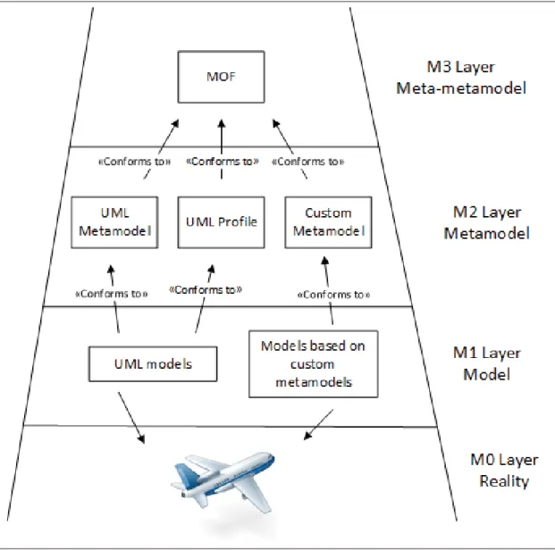
are said to be in «conformance» with the modeling language’s meta-model which is in turn in conformance with its own meta-model. Because meta-models are also models, they are represented using a modeling language called meta-meta-model. However this way to define meta-models introduces, in theory, an infinite number of meta-meta-model definitions. To cope with this problem, the Object Management Group (OMG) introduced a meta-modeling language within its four-level modeling framework, the Meta-Object Facility (MOF) (OMG, 2015). MOF is a meta modeling language for defining other modeling languages, including MOF itself. Figure 1.3 provides an overview of the four-level modeling framework introduced by the OMG. Models at the M0 level represent entities of the real world that are to be modeled (for example an aircraft). Models at the M1 level are the actual models (e.g. a UML state machine diagram) that are created using the semantics and notations defined at the meta-model (M2) level. The Unified Modeling language (UML) is one of the most common modeling language of level M2 whose base meta-meta-model is MOF (M3).
Models may be used by various stakeholders to represent different concerns of a system. In this context, models are used with two distinct objectives to reason about the system (Selic, 2007): 1) provide multiple perspectives on the system and 2) provide multiple levels of abstraction. The former, commonly referred to as «views» are the representation of various concerns of the system. A single view describes in details a specific concern of a system and when grouped together, views provide the complete description of the modeled system. Regarding the abstraction levels, models at the highest level are closer to the domain’s problem and those at the lowest level include implementation details. Huhn & Hungar (2010) identified use cases where platform independent models can be used when developing software related to safety-critical systems. Models can be used at every stage of the software life cycle. These use cases are: (1) the specification of the software requirements, (2) the definition of the software architecture and its evolution, (3) code generation, (4) verification,(5) validation and (6) certification.
Figure 1.3 OMG’s four-level architecture. Adapted from Djuri´c et al. (2005)
1.2.1 Domain specific modeling
To face problems emerging in specific domains of application, domain specific languages have proven their efficiency to overcome the complexity of software development project (Voelter et al., 2013). In the context of model driven engineering, there is an increase in the use of domain specific modeling languages (DSML) because they enable (Voelter et al., 2013): 1) a better expression of the solutions to the problems faced in a particular domain of application by using dialect and constructs pertaining to the domain, and 2) the capture of the domain knowledge,
easing its exchange and reuse among the involved stakeholders. Examples of DSML include Simulink, SCADE, MARTE or SysMl.
According to Selic (2007) and Lagarde et al. (2008), there exist three primary methods for the creation of a domain specific modeling language, two of which are based on an existing language: 1) the extension of an existing modeling language, 2) the refinement of an existing language and 3) the definition of the modeling language from scratch.
Among these methods, the refinement of an existing modeling languages is the most practical and cost effective solution to design a domain specific modeling languages (Selic, 2007). The reason lies behind the quantity of reuse that such solution allows. Indeed, existing language might provide an extension mechanism (i.e. UML profile) and tools might provide support for such mechanism. Finally, the refinement of an existing language requires less training to become familiar with the refined language.
The extension or refinement of an existing modeling language are the preferred methods among modeling language designers due to the benefit offered by these two methods. Using an existing modeling language as a basis allows designers to benefit from the knowledge revolving around the used technology to better tackle a domain’s problem. Furthermore these two methods allow a faster integration of new domain specific modeling languages within the development teams. One such modeling language that allows its extension and refinement is the unified modeling language (UML). Extension is done through mechanisms provided by the language while refinement add new concepts to the language which might introduce some incompatibilities with existing tool and environments.
1.2.2 UML and its extension mechanisms
The unified modeling language (UML) is an OMG’s standardized general purpose modeling language. It is a de-facto modeling language used throughout the software development life cycle: specification, design, and documentation. UML is used in a broad range of areas such as system, hardware, and even business process modeling. This wide usage is due to two
reasons. The first one is because UML is a general purpose language that enables to represent a system using multiple views and with different levels of abstraction. The second reason is the UML capability to be both extended and/or refined for the specific needs of a domain. The UML meta-model provides a built-in mechanism, called UML profiles to support the extension approach to designing domain specific modeling language.
UML profiles have the advantage, compared to the refinement of an existing meta-model, of reducing the cost to develop a domain specific modeling language. In fact, a number of existing UML modeling tools support the definition of UML profiles. Furthermore, the cost of training people to use UML profiles is greatly reduced because software engineers are generally familiar with UML and its profile mechanism. The effort required to define the syntax and semantic of a domain specific modeling language using the UML profile mechanism is also reduced as profiles have to remain consistent with the semantic defined by the UML meta-model (Selic, 2007). As such a profile cannot be used to define a new meta-model. Rather, the objective of profiles is to offer a straightforward mechanism to adapt the UML meta-model with constructs of a particular domain. Figure 1.4 displays the core concepts of UML profiles as defined within the UML meta-model.
An UML Profile is a specialization of the UML Package. A profile defines a number of stereotypes which add non-standard semantics to the model elements on which they are applied. Stereotypes are classes that extend base meta-classes. They may include properties and may be accompanied by constraints enforcing rules that are applicable to the stereotypes. To define such constraints, the OMG provides the Object Constraint Language (OCL) (OMG, 2014b). Figure 1.5 provides a simplified example of an UML profile for Enterprise JavaBeans (EJB). The profile defines the abstract stereotype Bean that is required to be applied to the Component metaclass. In other words, it means that an instance of either the Entity or Session stereotype must be applied to each instance of Component. Furthermore this profile defines constraints to verify that models are well formed. Example of such constraint include that a component should not be generalized or specialized.
Figure 1.4 UML meta-model: Profile mechanism definition (OMG, 2015).
Despite being a rather simple mechanism to create domain specific modeling language, there exist no standardized methodology to guide in the design of UML profiles. However study of various profiles revealed an approach that is common to build an UML profile. Selic (2007), Lagarde et al. (2008) and Fuentes-Fernández & Vallecillo-Moreno (2004) describe this process to design UML profiles in a similar manner. The general approach to define UML profiles shall be composed of the following steps: 1) the profile designer with help from domain specialist defines the conceptual domain model, 2) the profile designer realizes a transformation of the domain’s concepts into stereotypes by mapping the domain concepts to the appropriate UML meta-classes and 3) the profile is reviewed to verify its consistency against the UML meta-model. Figure 1.6 provides a small example of the mapping of a conceptual model into an UML profile. The conceptual model introduces concepts for a Simple Real Time System (SRTS). A Task represents any resource that can be scheduled, it contains a reference to one Scheduler that shall be defined by its SchedulingPolicy. Furthermore a Task has an EntryPoint and has a set of services (atomic and non atomic). The resulting profile is defined by creating a stereotype for each of the defined concepts. Concepts Scheduler and Task are extending the Class metaclass. SchedulingPolicy extends the DataType metaclass. Finally, Service and EntryPoint extend the Operation metaclass.
a) Conceptual model
b) Profile diagram
Figure 1.6 Example of the mapping of a conceptual model into a UML profile. Adapted from Lagarde et al. (2008)
1.3 Approaches for modeling safety critical systems
Many model-based approaches have been proposed recently to support the development of software in the context of safety-critical systems. Although our research problem is particularly aimed at airborne software and their development according to DO-178C, we have explored a broader range of application domains for model-based approaches, extending the scope of our literature review to approaches pertaining to the development of safety-critical software in general. The reason behind this wide scope, is due to the fact that safety-critical software share similar properties and challenges independently from their domain of application such as railway, aerospace, energy and medical devices.
Thus, we first present the approaches that are domain-independent in Section 1.3.1. Then, we introduce the approaches that are domain-dependent in Section 1.3.2. Specifically we introduce UML profiles that target various specific safety-critical systems and those that specifically target avionic systems.
1.3.1 Domain-independent approaches
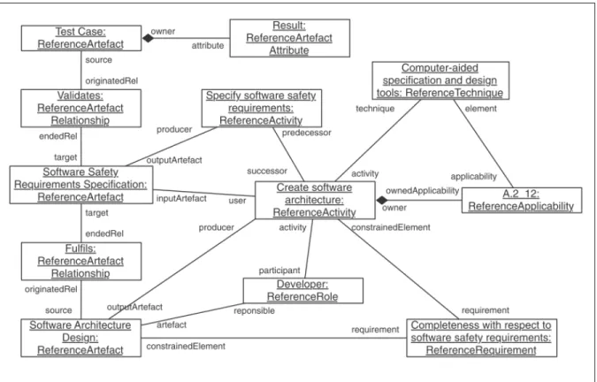
Generally, safety compliance is not based on just one standard but a corpus of regulatory standards. In this context, De la Vara et al. (2016) introduce the Reference Assurance Framework (RAF) metamodel. Its purpose is to express key concepts and relations used for demonstrating safety compliance that are extracted from multiple sources (i.e. safety standards, specific domain recommended practices, and company specific practices). The RAF meta-model provides an unified mean to create models used for safety assurance and certification. An excerpt of a RAF model for IEC 61508 is provided in Figure 1.7 and depicts the use of some of the main concepts of the RAF meta-model. Among these concepts, ReferenceRequirement captures conditions that might have to be fulfilled, a ReferenceActivity defines activities that must be executed. These activities produce ReferenceArtifact that are the data that must be managed and provided for certification. A ReferenceTechnique specifies the way an activity is performed or artifacts are created.
Figure 1.7 Excerpt of a RAF model for IEC 61508. Adapted from De la Vara et al. (2016).
Safety standards rely on the traceability of safety evidence throughout the complete software life cycle to both demonstrate compliance with standard and support claims about the safety of the software product. Commonly required safety evidence includes: test cases, test results, and system specifications (requirements). Because suppliers must collect and maintain these evidence, the explicit specification of the traces between these artifacts is an important aspect to support the certification process of safety critical systems.
Work from Nair et al. (2014) introduces a Safety Evidence Traceability Information Model (SafeTIM). Its objective is to provide a broad overview of safety evidence traceability in the context of safety critical systems. The proposed model captures the traces and evidence information that must be created and maintained to show compliance with safety standards. SafeTIM was developed based on an extracted set of traces that are necessary for safety evidence. As observed on Figure 1.8, the principal concept that traces to all of the concepts of the model is
the Artefact concept, which represent an individual and identifiable unit of data that is managed throughout the software life cycle. These artifacts are used as piece of evidence for claims, which are propositions that are being asserted in relation to system safety. Those piece of evidence are accompanied by arguments, which are body of information that are provided in order to establish a claim about the system safety. Artefacts are the output and are also required as input data for various activities of the software life cycle.
Figure 1.8 The Safety Evidence Traceability Information Model (SafeTim). Adapted from Nair et al. (2014).
Nejati et al. (2012) introduce a SysML based approach to address traceability between safety requirements and their design implementation. An algorithm that analyses the association between a requirement and its implementation is provided to extract design slices. Design slices provide a detailed view of the system from the perspective of a specific safety requirement. These are extracted from the overall design and capture the design aspects related to a target requirement. Such slice enables the analysis of the implementation of a safety requirement by removing the design elements that are irrelevant for the requirement under analysis. Figure 1.9
provides an example of the resulting design slice that is extracted from the design implementation of a provided requirement.
a) Requirement
b) Design c) Design-slice
Figure 1.9 Example of a requirement (a) and its related design slice (c) that is extracted from a design model (b). Extracted from Nejati et al. (2012).
1.3.2 Domain-specific approaches
1.3.2.1 UML profiles targeting various specific safety critical systems
Berkenkötter & Hannemann (2006) propose a domain specific language in the form of a UML profile for the railway control systems domain (RCSD). The RCSD profile enables the precise modeling of the static description of railway networks and their associated dynamic aspects. Networks are comprised of elements such as track segments, points, signals, and sensors. These elements are the physical entities that constitute a network of tracks on which trains are moving through pre-defined routes.
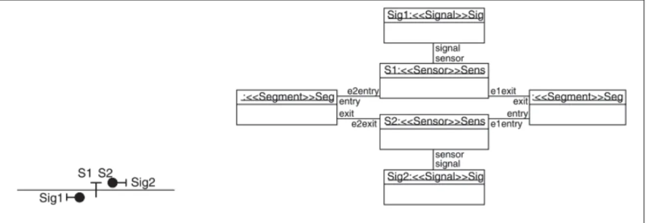
The profile models the domain using a combination of class diagrams and object diagrams. Class diagrams are used to represent problems of the railway domain (i.e. tramway and railroad models) whereas object diagrams capture instances of these problems (i.e. the explicit track layout). The object diagram uses either the UML notation or a notation introduced by the authors based on the symbology of the railway domain. Figure 1.10 shows an overview of an object diagram using the specific notation for the railway domain introduced by the RCSD profile (left side of the figure) and the UML notation (right side of the figure).
Figure 1.10 Object diagrams representing two track segments along their sensors and signals using both UML and RCSD notation. Extracted from
The dynamic aspect of the track network is defined as a timed state transition system (TSTS). The timed transitions are embedded locally in the profile’s elements. To ensure safety through the network, a controller is defined and added to the network model and remain independent from he physical elements captured in the model. The controller includes the safety conditions for running the systems. The controller model is defined using a strict mathematical model. This mathematical definition enables to prove the violation of the safety conditions for the running system by using bounded model checking techniques.
Panesar-Walawege et al. (2013) and Kuschnerus et al. (2012), both defined UML profiles aimed at the expression of certification-related information for IEC 61508 standard. In particular, Panesar-Walawege et al. (2013) proposed an approach to support safety-critical suppliers in creating safety evidence needed to show compliance with a specific safety standard. The approach is based on a process that assists preparing of the certification evidence. This process is comprised of 4 phases as shown in Figure 1.11. The first two phases, occurring only once per targeted standard, are similar to the methodology described in the work of Lagarde et al. (2008) and Selic (2007) for defining UML profiles. The first phase consists in the definition of the conceptual model that captures the concepts of the standard under scrutiny related to certification evidences. The second phase, consists in the mapping of these concepts to the UML meta-model to obtain an UML profile. The third phase of this approach is the application of the profile to the domain model of the system undergoing certification. The resulting model allows the capture of precise links between the system’s concepts and standard’s concepts. In the last phase, the resulting model is instanciated to create evidence submitted for certification.
Figure 1.11 The process for the creating evidence of a safety standard. Extracted from Panesar-Walawege et al. (2013).
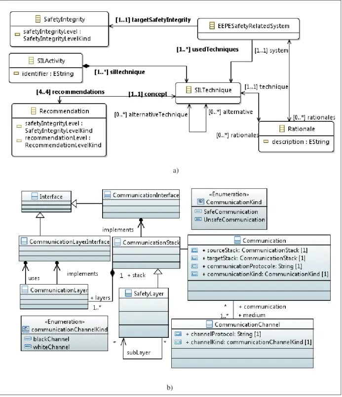
Kuschnerus et al. (2012) introduced a UML profile based on the concepts extracted from IEC 61508. The profile uses models as baseline artifacts for certification documentation. The process to extract the domain model and its mapping to the UML meta-model that defines the profile is similar to the methodology described by Lagarde et al. (2008). The domain model extracted from the standard is divided into two categories. The first category of concepts is related to the definition of the safety process defined by IEC 61508 and captures the activities and recommended techniques as defined by the standard. This category includes the definition of monitoring concepts for the process of designing the architecture. The second category of the domain model defines concepts that are specific to the standard such as safety terms and their relations. This include safety functions and the certification status of software modules. An excerpt of the domain model is provided in Figure 1.12.a. It contains concepts related to the first part of the domain. It defines the relations between an Electrical/Electronic/programmable Electronic(E/E/PE) safety-related system, the safety integrity the system needs to conform with and the techniques that are performed in order to realize the system. SIL Activity represents activities defined by the standard and each of these should use one or more techniques depending on the targeted integrity level. Figure 1.12.b provides communication concepts of the second part of the domain. In a safety-critical system, a communication shall either be safe (i.e. transmission of data is verified by a checksum) or unsafe. Communication is established between multi-layered communication stack using a channel as a medium. Each channel defines the protocol it uses in order to transmit data. This profile focused mainly on safety requirements.
a)
b)
Figure 1.12 Excerpt of Kuschnerus et al.’s domain model. Adapted from Kuschnerus et al. (2012).
Safety-critical systems behavior are often dependent on various timing properties, thus the correct timing of such systems is part of their functional correctness. In this context, the UML profile for Modeling and Analysis of Real-Time Embedded System (MARTE) (OMG, 2011) primary concern is to capture the aspects related to real-time in embedded systems. MARTE is structured as a hierarchy of sub-profiles, as provided in Figure 1.13.
Figure 1.13 Architecture of the MARTE profile (OMG, 2011).
The "Marte foundations" package defines the foundation on which the rest of MARTE is built. It defines four basics sets of extensions to UML, these sub-profiles are the following:
• Non-functional properties (NFP): provides modeling constructs for declaring, qualifying, and applying semantically well-formed non-functional aspects of UML models. It is
completed by the "Marte annexes" sub-profile Value Specification Language (VSL) which is a textual language used for declaring algebraic expressions.
• Time: provides the concepts for defining time in applications and for manipulating its underlying representation.
• Generic resource modeling (GRM): provides an ontology of resources enabling the mod-eling of common computing platforms (i.e. resources on which an application is allocated for computation) along with the concepts needed for specifying resources usage.
• Allocation modeling (Alloc): provides the concepts pertaining to the allocation of func-tionalities to the entities responsible for their realization. These concepts may be either time allocation (i.e. scheduling) or spatial allocation (i.e. hardware allocation).
The remaining parts of MARTE are separated into two categories of extensions: "MARTE design model" and "MARTE analysis model". Design models are created using annotations containing concerns from real-time or embedded systems that are provided by the High-level Application modeling (HLAM) sub-profile. Also MARTE allows the modeling of component based systems through its Generic Component Model (GCM) sub-profile. Analysis models are created using the Generic Quantitative Analysis Modeling (QGAM) and its two refinements dedicated to both schedulability (SAM) and performance (PAM) analysis.
1.3.2.2 UML profiles for avionics software
Wu et al. (2015) have developed a methodology called Safety Oriented Architecture Mod-eling (SOAM). The method focuses on the design of a component centric architecture for avionic software in the context of DO-178C. More precisely this approach emphasizes on the notions related to the safety of software components. The method introduces an UML profile named SafetyProfile. Authors claim that the profile captures safety properties in accordance with DO-178C guidelines that apply to software components and their related interfaces. Fig-ure 1.14 presents an excerpt from the conceptual model from which the profile was derived.
The profile focuses on components-based architecture design. In fact the conceptual model focuses on the communications between components, the definition of the component’s inter-faces and their monitoring. The SafetyComponent is the main concept of this model. A
SafetyComponentcommunicate with another through a SafetyChannel. A component
may detect a Fault and needs to handle it through various MitigateAction. A component defines SafetyInterface that are accessed throught its defined SafetyPort.
Figure 1.14 Excerpt of the conceptual model used for building SafetyProfile. Adapted from Wu et al. (2015).
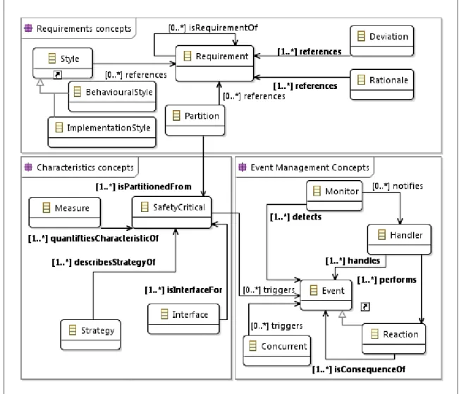
Zoughbi et al. (2010) introduced SafeUML, a UML profile based on DO-178B. Its purpose is to capture the safety related requirements that are allocated to software and to monitor their implementation through the software design. Furthermore the profile intends to improve com-munication and collaboration between safety engineers, software engineers and the certification authorities. The profile is organized into packages, each package includes a set of related concepts. The concepts from which the profile is developed are grouped into five packages: 1) the Requirements package contains the concepts that are needed to express software
require-ments, their refinement as well as the traceability of the requirements to design artifacts, 2) the Characteristics package contains concepts to identify design elements having a direct impact on safety by specifying the software level that is attached to these elements along with the failure conditions that are associated to these elements, 3) the Event Management package that defines the concepts of events and the actions related to their capture, 4) the Configuration package that defines the concepts to capture elements related to software configuration, user modifiable software and change control, and 5) the Replication package containing concepts to address software redundancy. Figure 1.15 provides an overview of three of the packages that constitute this conceptual model. A Partition is created to fulfill one or more Requirements, and is partitioned from one or more SafetyCritical entities. A SafetyCritical entity may trigger Events that must be monitored in order to be detected in the system. The Monitor is in charge of notifying various Handlers that perform Reactions associated to the captured event.
Although DO-178B does not provide guidelines for the use of model based software devel-opment and verification, Stallbaum & Rzepka (2010) introduced a UML profile to enable the specification of DO-178B compliant test models. The purpose of these test models is twofold. The first purpose is to enable testing activities of the software as per DO-178B guidelines. The second is to enable the use of the models as artifacts supporting evidence for the certification process by capturing the required relevant testing information. From the analysis of the standard, they identified the information that test models must capture and designed an UML profile, which is depicted in Figure 1.16. The profile is used by applying the TME (TestModelElement) stereotype to each model element to define test and certification relevant information. A TME is the entity that represents a test model element. It comprises the system behavior and certification related information. Examples of TME include activity, interaction or state. The Requirement stereotype is used to specify software requirements and the association between requirements and TMEs supports requirement-based test coverage analysis. The SafetyRationale stereotype specifies whether or not an element of the model is safety-critical and includes the rational for the element’s criticality. The Interface stereotype is used to specify hardware/software interfaces. The SoftwareComponent stereotype defines self-contained unit of the software that implement
Figure 1.15 Excerpt of Zoughby et al.’s safety-related conceptual model. Adapted from Zoughbi et al. (2010).
distinct functionality of the system. The profile enables the capture of the following testing needs requested by DO-178B: (1) traces between model elements and their related requirement(s), (2) identification of the software level(s) along the corresponding rationale, (3) identification of the conditions related to normal range and robustness test cases, (4) identification of the testing method (i.e. hardware/software integration, software integration, and low-level tests), (5) identification of hardware/software interfaces and their parameters, (6) traces between model elements and software components, (7) traces between model elements and source code, and (8) the type of the traces.
Figure 1.16 UML profile for DO-178B compliant test models. Adapted from Stallbaum & Rzepka (2010).
1.4 Discussion
The studied approaches contribute in different ways to support the development and certification of safety-critical software. Table 1.2 provides an overview of the domain of application, the objectives, the targeted standard and the software life cycle/ concerns of the approaches studied in Section 1.3.
Table 1.2 Summary of the studied approaches to model various safety critical systems.
Approach Domain Objectives Targeted
standard Software life cycle process-es/ Concerns De la Vara et al. (2016) Multiple do-mains Express key concepts and relations used to demonstrate safety compli-ance extracted from multiple standards Multiple standards (including DO-178C) Safety as-surance and certification
Nair et al. (2014) Provide a model
of safety evidence traceability
Traceability
Nejati et al. (2012) Extract design
slices related to a requirement
Traceability of requirements to design
Berkenkötter & Han-nemann (2006)
Transportation:
Railway,
Sub-way
Model the static and dynamic as-pects of the do-main Software Design Panesar-Walawege et al. (2013) Electrical Electronic Programmable Devices
Support the pro-cess of collecting evidence for the support of certi-fication against a standard
IEC 61508 Safety
Require-ments Kuschnerus et al. (2012) Electrical Electronic Programmable Devices
Model the stan-dard
IEC 61508 Planning
Object
Manage-ment Group (OMG) (2011)
Profil: MARTE
Reel time em-bedded software
Capture and an-alyze real time properties of a software
Specification of requirements and design
Approach Domain Objectives Targeted standard Software life cycle process-es/ Concerns Wu et al. (2015) Profil: SafetyProfile
Avionic Capture safety
re-lated aspects as-signed to a soft-ware component DO-178C Software Design Process Zoughbi et al. (2010) Profil: SafeUML
Avionic Capture software
requirements and monitor their im-plementation
DO-178B Software
Re-quirements Process,
Soft-ware Design
Process Stallbaum & Rzepka
(2010)
Avionic Capture test data
as UML models
DO-178B Software
Verifi-cation Process Several of the explored approaches emphasize the possible ambiguous interpretation of textually defined safety standards. Because of the need to provide evidence that a standard was adequately applied for the development of certifiable software, an ambiguous interpretation of the standards results in major risks for certification. Misinterpretation of a standard may most possibly result in the creation of inadequate evidence hindering an already difficult certification process. This issue calls for a unique interpretation of the standards. As a result, the introduction of model-based development may help in reducing or suppressing the possible misinterpretations by offering the capability to model the standards. Thus the studied approaches provide an explicit interpretation of the standard through the models they propose. Furthermore modeling of safety standards may lead to an automation of certain aspects of the production of artifacts supporting certification.
Many approaches specifically tackle avionics software (e.g. Wu et al. (2015); Zoughbi et al. (2010); Stallbaum & Rzepka (2010)), however they propose meta-models and profiles that target specific concerns in the software development. Stallbaum & Rzepka (2010) target the software