Cartesian Control of a Cable-Driven Haptic Mechanism
Martin J.D. Otis, Vincent Duchaine, Greg Billette, Simon Perreault, Clément Gosselin and Denis Laurendeau
X
Cartesian Control of a Cable-Driven
Haptic Mechanism
1Martin J.D. Otis, Vincent Duchaine, Greg Billette,
Simon Perreault, Clément Gosselin and Denis Laurendeau,
Laval University
Canada
1. Introduction
Haptic devices operated through a communication network require a trade-off between the stability of the interaction and the quality of the haptic display. A haptic device must be designed to provide the best haptic display in order to reproduce the tactile sensation of virtual objects, rigid or soft, while ensuring a stable operation to guarantee user safety. The challenges are greater when considering a locomotion interface where a walker can produce large wrenches. A Cable-Driven Locomotion Interface, used as a peripheral in a virtual environment, is designed to address some of the aforementioned issues, since the use of cables as a mechanical transmission is known to provide many advantages such as low inertia, which is helpful in attaining high speeds and high accelerations, and the potential lengths of the cables can allow for large workspaces. Using this mechanism, a walker could navigate in a virtual environment with the aid of two haptic platforms (one for each foot) which can be regarded as two independent parallel robots constrained to six degrees of freedom and sharing a common workspace.
The architecture of the framework is composed of two components: the virtual environment
manager and the controller manager. The former contains the definition of the environment in
which the user navigates, as expressed by a graphic rendering engine and a communication interface. The second component computes and controls the wrenches from two physical models to accurately simulate soft and rigid virtual objects. The challenge of high impact dynamics is addressed with the help of specialized reels that is also introduced as a potential solution to the issue. The aim of these new reels is to reproduce the vibrations that would normally be encountered during such an impact.
From kinematic-static duality principle, the total wrench applied on a platform is distributed optimally in each cable tension by an optimal tension distribution algorithm thereby allowing the haptic simulation of virtual objects using hybrid admittance/impedance control with multi-contact interactions. In the context of
1© [2009] IEEE. Reprinted, with permission, from Hybrid control with multi-contact
interactions for 6DOF haptic foot platform on a cable-driven locomotion interface,
Symposium on HAPTICS 2008 by Otis, Martin J.-D. et. al.
robot cooperation, some practical aspects of the software design for achieving a safe control (for avoiding accidents and injuries) with a safety management plan are presented. Finally, some stability issues are also developed specifically for the cable-driven parallel mechanism.
1.1 Review
The Cable-Driven Locomotion Interface (CDLI) design presented here is based on the concept of programmable platforms with permanent foot contacts, such as Gait Master (Iwata et al., 2001), (Onuki et al., 2007) and K-Walker or the Virtual Walking Machine in (Yoon et al., 2004). CDLI employs two independent cable-driven haptic platforms constrained in six degrees of freedom (Perreault & Gosselin, 2008). Each platform is attached to a foot of the walker. Its control system and its geometry are designed so as to support a wide range of walking patterns including left/right turns and going up/down slopes or stairs that are either rigid or soft virtual surfaces or objects. In the following paragraphs, a control algorithm made specifically for cable-driven platforms is presented to address the issue of the interactions between the virtual foot models linked to the platforms and any virtual object such as but not limited to uneven terrain.
Several concepts of locomotion interfaces have been developed in order to provide a better feeling of immersion in a virtual environment and for automated walking rehabilitation. For instance, the Rehabilitation Robot LOKOMAT (Bernhardt et al., 2005) uses a hybrid force-position control method for which the force component adjusts the movement of an actuated leg orthosis so as to influence the LOKOMAT's motion and to automate user gait-pattern therapy. Such a control method is implemented in the context of the Patient-Driven Motion Reinforcement paradigm. HapticWalker is a programmable robotic footplate device that allows arbitrary foot movements during user gait training via specialized motion generation algorithms (Schmidt et al., 2005). However these control strategies are not well adapted to a CDLI as well as haptic rendering of contacts with any virtual objects or uneven terrains. In fact, a CDLI shows substantial advantages over conventional locomotion interfaces and has the potential to achieve better performances than other devices. For instance, the haptic foot platform in a CDLI can reach higher accelerations and can move in a larger workspace. Some designs involving cable-driven mechanisms were devised as the primary haptic display in a virtual environment. For instance, cable-driven devices have proven their efficiency as haptic interfaces in virtual sport training such as a tennis force display (Kawamura et al., 1995) and a catch playing simulator (Morizono et al., 1997). In this chapter, it is shown that a hybrid admittance/impedance strategy for controlling the CDLI combines the benefits of both control classes and exploits the contact points geometry and the physical properties (stiffness, friction, etc.) of the virtual surface colliding with the virtual foot model. Within the CDLI control algorithm, the measured action wrenches imposed by the walker's feet move the platforms while a virtual reaction wrench moves the walker in the virtual environment in the event that a contact is detected between a virtual object and the virtual foot model. The software also exploits the Newton Game DynamicsTM
engine, labeled “Newton engine” in the following, for simulating rigid body interactions. The second section of this chapter presents the software architecture for controlling the haptic foot platform. The third and the fourth sections covers the development of the control strategy for multiple-contact points geometry that is used for performing hybrid-controlled interactions in a CDLI. The fifth one presents a custom physics engine developed under QNX OS for force rendering on a haptic foot platform so as to manage soft object
interactions. This physics engine includes a Force Optimization Problem (FOP) to distribute the wrench at each contact point uniformly and optimally. This custom engine is designed to overcome some drawbacks of the Newton engine, such as transient force computation and object penetration that occurs when a contact is detected between the virtual foot model and a compliant surface. Finally, the last section of the chapter presents simulations of the control strategy with the physics engines in normal gait walking conditions.
1.2 The geometry of the CDLI
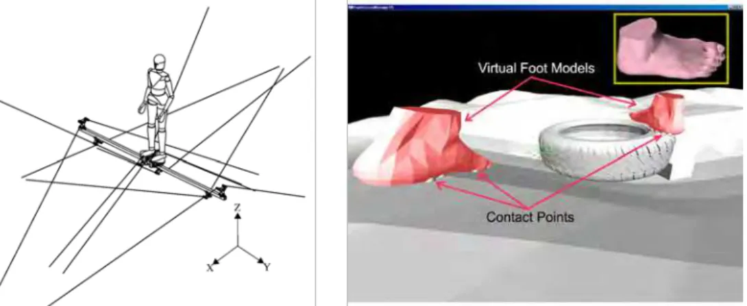
As shown in figure 1, the geometry of the CDLI is optimized to cover the largest workspace possible in a limited volume (i.e. the overall dimension of the complete CDLI) so as to avoid cable interferences and to minimize human-cable interferences while the user is walking (Perreault & Gosselin, 2008). It must be noted that due to the unilaterality of the actuation principle, a cable-driven parallel platform needs at least seven cables in order to control a six DOF platform. Since each platform has six DOF so as to emulate human gait (Yoon & Ryu, 2006) and all cable attachment points are chosen so as to reach an optimal workspace, each haptic foot platform is actuated by eight cables.
The dimensions of the workspace along the X, Y and Z axis are respectively 2 metres, 0.6 metre and 1 metre, all within the overall dimensions of the complete CDLI whose size is approximately 6.0 metres by 3.5 metres by 3.0 metres. These dimensions allow users to perform a wide range of walking patterns.
The model of the virtual foot in the virtual environment, shown in figure 2, is mathematically related to the haptic foot platform by a translation vector and a rotation matrix between their respective reference frames.
Fig. 1. CAD model of the complete CDLI
taken from (Perreault & Gosselin, 2008) Fig. 2. Virtual foot models in contact withvirtual objects
1.3 Control Classes for Haptic Rendering
Two control classes are generally employed for haptic rendering on the platforms: an impedance control class and an admittance control class similar to those described in (Carignan & Cleary, 2000). Since both control classes use pose and wrench inputs, they are
robot cooperation, some practical aspects of the software design for achieving a safe control (for avoiding accidents and injuries) with a safety management plan are presented. Finally, some stability issues are also developed specifically for the cable-driven parallel mechanism.
1.1 Review
The Cable-Driven Locomotion Interface (CDLI) design presented here is based on the concept of programmable platforms with permanent foot contacts, such as Gait Master (Iwata et al., 2001), (Onuki et al., 2007) and K-Walker or the Virtual Walking Machine in (Yoon et al., 2004). CDLI employs two independent cable-driven haptic platforms constrained in six degrees of freedom (Perreault & Gosselin, 2008). Each platform is attached to a foot of the walker. Its control system and its geometry are designed so as to support a wide range of walking patterns including left/right turns and going up/down slopes or stairs that are either rigid or soft virtual surfaces or objects. In the following paragraphs, a control algorithm made specifically for cable-driven platforms is presented to address the issue of the interactions between the virtual foot models linked to the platforms and any virtual object such as but not limited to uneven terrain.
Several concepts of locomotion interfaces have been developed in order to provide a better feeling of immersion in a virtual environment and for automated walking rehabilitation. For instance, the Rehabilitation Robot LOKOMAT (Bernhardt et al., 2005) uses a hybrid force-position control method for which the force component adjusts the movement of an actuated leg orthosis so as to influence the LOKOMAT's motion and to automate user gait-pattern therapy. Such a control method is implemented in the context of the Patient-Driven Motion Reinforcement paradigm. HapticWalker is a programmable robotic footplate device that allows arbitrary foot movements during user gait training via specialized motion generation algorithms (Schmidt et al., 2005). However these control strategies are not well adapted to a CDLI as well as haptic rendering of contacts with any virtual objects or uneven terrains. In fact, a CDLI shows substantial advantages over conventional locomotion interfaces and has the potential to achieve better performances than other devices. For instance, the haptic foot platform in a CDLI can reach higher accelerations and can move in a larger workspace. Some designs involving cable-driven mechanisms were devised as the primary haptic display in a virtual environment. For instance, cable-driven devices have proven their efficiency as haptic interfaces in virtual sport training such as a tennis force display (Kawamura et al., 1995) and a catch playing simulator (Morizono et al., 1997). In this chapter, it is shown that a hybrid admittance/impedance strategy for controlling the CDLI combines the benefits of both control classes and exploits the contact points geometry and the physical properties (stiffness, friction, etc.) of the virtual surface colliding with the virtual foot model. Within the CDLI control algorithm, the measured action wrenches imposed by the walker's feet move the platforms while a virtual reaction wrench moves the walker in the virtual environment in the event that a contact is detected between a virtual object and the virtual foot model. The software also exploits the Newton Game DynamicsTM
engine, labeled “Newton engine” in the following, for simulating rigid body interactions. The second section of this chapter presents the software architecture for controlling the haptic foot platform. The third and the fourth sections covers the development of the control strategy for multiple-contact points geometry that is used for performing hybrid-controlled interactions in a CDLI. The fifth one presents a custom physics engine developed under QNX OS for force rendering on a haptic foot platform so as to manage soft object
interactions. This physics engine includes a Force Optimization Problem (FOP) to distribute the wrench at each contact point uniformly and optimally. This custom engine is designed to overcome some drawbacks of the Newton engine, such as transient force computation and object penetration that occurs when a contact is detected between the virtual foot model and a compliant surface. Finally, the last section of the chapter presents simulations of the control strategy with the physics engines in normal gait walking conditions.
1.2 The geometry of the CDLI
As shown in figure 1, the geometry of the CDLI is optimized to cover the largest workspace possible in a limited volume (i.e. the overall dimension of the complete CDLI) so as to avoid cable interferences and to minimize human-cable interferences while the user is walking (Perreault & Gosselin, 2008). It must be noted that due to the unilaterality of the actuation principle, a cable-driven parallel platform needs at least seven cables in order to control a six DOF platform. Since each platform has six DOF so as to emulate human gait (Yoon & Ryu, 2006) and all cable attachment points are chosen so as to reach an optimal workspace, each haptic foot platform is actuated by eight cables.
The dimensions of the workspace along the X, Y and Z axis are respectively 2 metres, 0.6 metre and 1 metre, all within the overall dimensions of the complete CDLI whose size is approximately 6.0 metres by 3.5 metres by 3.0 metres. These dimensions allow users to perform a wide range of walking patterns.
The model of the virtual foot in the virtual environment, shown in figure 2, is mathematically related to the haptic foot platform by a translation vector and a rotation matrix between their respective reference frames.
Fig. 1. CAD model of the complete CDLI
taken from (Perreault & Gosselin, 2008) Fig. 2. Virtual foot models in contact withvirtual objects
1.3 Control Classes for Haptic Rendering
Two control classes are generally employed for haptic rendering on the platforms: an impedance control class and an admittance control class similar to those described in (Carignan & Cleary, 2000). Since both control classes use pose and wrench inputs, they are
instead defined by the output or the feedback loop. The properties of each approach are compared in table 1. The Cobotic Hand Controller (Faulring et al., 2007) and the HapticMaster (van der Linde & Lammertse, 2003) are both mechanisms that use admittance control. On the other hand, the Excalibur (Adams et al., 2000) and the Phantom (McJunkin & al., 2005) haptic devices have been designed as impedance displays that use impedance control.
Indeed, two virtual object models could be defined: an admittance model and an impedance model. Using linear circuit theory (quadripole or two-ports models), there are four possible topologies described by the immitance matrices: the impedance matrix, the admittance matrix, the hybrid matrix and the alternate hybrid matrix that the controller could manage as described in (Adams & Hannaford, 1999).
The hybrid control strategy combining these two control classes (interacting with the both virtual object models) ensure that free movements and contact with a rigid virtual object are rendered realistically by the platforms. Section 4 describes a method for selecting the appropriate control class using both the geometry of the contact points and the virtual object properties.
Impedance-controlled system (impedance
control with force feedback) Admittance-controlled system (admittance control with position/velocity feedback)
Controls the wrench applied by the haptic
foot platform Controls the pose or velocity of the haptic device
Is subject to instabilities when the user
releases the device Is subject to instabilities when the stiffness of the user's legs increases Can simulate highly compliant virtual
objects Can simulate an unyielding virtual object
Table 1. Comparison of the control classes
1.4 Stability issues
The capability for a human to stabilize an unstable system or even to destabilize a stable system is a recurrent problem in the haptic interface control. Two methods are developed in the literature for stability analysis. The first one is based on human and environment models (on-line or real-time computation of the muscle stiffness) in order to adjust an admittance model in the controller that gives pose setpoints computed from the user applied wrench measured at the end effector. This method consists in adjusting the control law for ensuring stability of the system (Tsumugiwa et al., 2002). The analysis of the stability could then be performed with different strategies such as Routh-Hurwitz, root-locus, Nyquist, Lyapunov or μ-analysis among others. In the other case, the second method does not use any model. This method analyses the transfer of energy inside the system like in (Hannaford & Ryu, 2002). On the other hand, there exist numerous stabilizing techniques such as those exploited in adaptive or robust control.
A stable haptic system dissipates more energy than the overall control system produces. However, this diminishes the realism of the haptic display as the dissipated energy
increases. It is therefore a trade-off between performance and transparency. In cable tension control applications the dissipated energy should be compensated for so as to lead the system toward an unstable regime. The stabilizing method uses a virtual damping parameter in order to dissipate accumulated energy with a passivity observer (PO) and a passivity controller (PC). This method was used also for compensating the delay on the network.
Friction hysteresis in reel increases vibrations in the cables when the reel's mechanical parts stick and slip. Furthermore, rigid contacts between the virtual object and the foot produce discontinuities in cable tensions that have a tendency to create or emphasize cable vibrations. Finally, the stiffness of the reel and of the mechanical structure should be at least larger than the one of the virtual object so that mechanical deformation cannot generate more instability. From this analysis, which excludes the electronic hardware, six types of instability inside a hybrid control architecture for a Cable-Driven Mechanism can be considered:
1. Cable vibration and tension discontinuities;
2. Mechanical design (stiffness of the overall mechanical structure including motorized reel, friction hysteresis, actuator dynamic, encoder resolution, etc.); 3. Hybrid control architecture with uncertainty (Cheah et al., 2003) and with flexible
joint (Goldsmith et al., 1999);
4. Contacts with a stiff virtual object with one or more contact points (Lu & Song, 2008);
5. Interaction between a human and a mechanism (Duchaine & Gosselin, 2009) and 6. Time delay (latency) over the network (Changhyun et al., 2008).
2. Software Architecture for Control
The hardware architecture is composed of two components: a soft real-time module implemented on a standard PC running Windows which manages the virtual environment with a graphic rendering engine, and a hard real-time module implemented on a standard PC running QNX whose primary tasks is to control and drive the cable-driven platforms and a server that ensures intercommunication and synchronization between different walkers. The software architecture is designed to exploit the above hardware and is thus composed of the two components shown in figure 3: the Virtual Environment Manager and the Controller Manager which are described in the next sections.
2.1 Virtual Environment Manager
The Virtual Environment Manager (VEM) is responsible for handling haptic objects (virtual foot model and virtual object), a physics engine, and a virtual user (an avatar) whose feet are shown to be moving in a virtual environment. The avatar therefore mimics the movements of the user so that he or she can observe his actions in the virtual environment. The virtual
user defines the characteristics of the walker who can observe the virtual environment in
coherence with his feet. For the physics engine, Newton Game DynamicsTM is used as a slave
engine while the master physics engine is implemented on a second PC using QNX OS in the controller manager as described in section 2.2. The communication between both physics engines is ensured by a client communication interface and a server communication interface.
The Haptic Scene Manager (HSM) is the main interface with which the virtual environment is built and configured. The HSM is responsible for configuring the Newton engine according to the simulation requirements.
Fig. 3. Software architecture
It is also responsible for the creation, set up, and destruction of virtual objects having a haptic presence in the environment. Besides the HSM, the haptic module uses two other managers for the hands (hand manager) and feet (foot manager that define the avatar). The foot
manager, which is connected to the virtual user, communicates with the controller manager
using a TCP/IP connection. Over this communication link, the Newton engine provides the contact points between each virtual foot model and the virtual object to the controller
manager and also provides the normal/tangent vectors to these contact points as well as the
penetration into the virtual object. Conversely, the controller manager responds to these inputs by providing the foot manager with the pose and the speed of the haptic foot platform resulting from the contact, as well as the total wrench computed by the custom physics engine which then moves the virtual foot model and the virtual object in the scene.
The communication link between the VEM and the controller manager must support a minimum transmission rate of approximately 100 Hz in order to transfer a burst of 512 bytes with a maximum latency of one millisecond. Although there are hardware solutions satisfying these requirements, the main issue still remains the latency of the asynchronous process which is only executed whenever possible. Some solutions for resolving communication bandwidth limitations are given in (Sakr et al., 2009), where a prediction approach is exploited with the knowledge of human haptic perception (Just Noticeable Differences of Weber's law). The definition of a deadband is used for data reduction. This deadband consists of velocity and pose threshold values where there are no significant new informations. In the proposed system described in this chapter, the quantity of data transmitted over the network is based on the selection of meaningful contact points from those evaluated by the Newton engine. In fact, only three points are required by the
controller manager to define the control class that will be applied in the appropriated DOF.
2.2 Controller Manager
The controller manager runs two processes: a hard real-time periodic process (labeled control
algorithm process) responsible for the hybrid control algorithm, and a soft real-time
asynchronous process that manages the virtual environment updates between the foot
manager and the control algorithm process. The periodic process can be pre-empted any time
by the asynchronous process. The rate of the periodic process for controlling the actuators and the sampling rate achieved for wrench sensing are both set at a multiple of the analog input signal number and has a minimal rate of 500 Hz, and in the best case, 1 kHz.
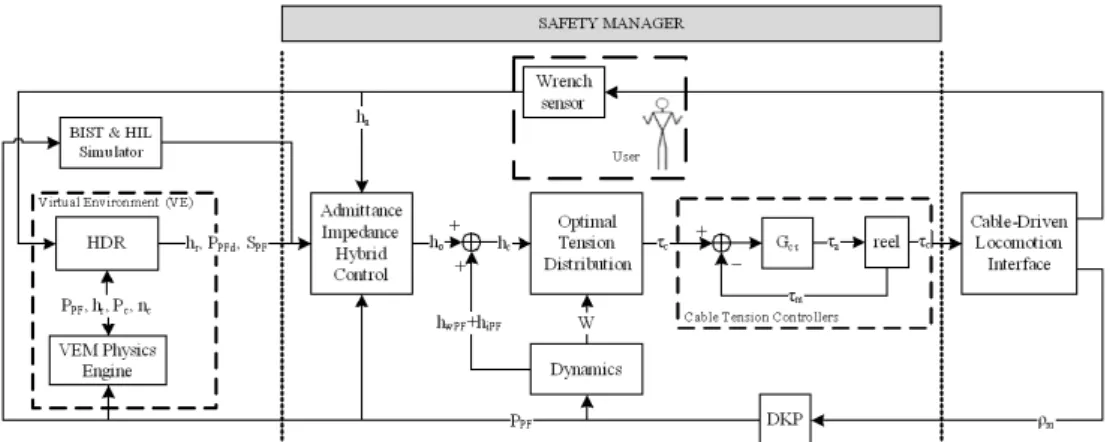
The virtual torquer in tandem with the control algorithm process runs the master physics engine (labeled Haptic Display Rendering (HDR) in figure 4) as well as a washout filter that maintains the walker at the centre of the workspace using a variable impedance model and position feedback as described in (Yoon & Ryu, 2006) and (Yoon. & Ryu, 2009).
Fig. 4. Simplified control algorithm process with interactions of both physics engines
The control algorithm process, detailed in figure 4, accepts one input (the output of a 6 DOF
wrench sensor) and produces two outputs (cable tensions τc and platform poses PPF ).
The appropriate reaction wrench hr is computed from the interaction between both
physics engines. These engines also determine whether the degrees of freedom for each platform should be controlled in impedance or in admittance. Depending on the selected
control class, the 6 DOF wrench sensor can produce, an action wrench ha which moves
each platform using a hybrid control scheme.
The total wrench hc applied at the centre of mass of the platform is balanced with
positive cable tensions using an Optimal Tension Distribution (OTD) algorithm as described in (Fang et al., 2004). The result being a set of equilibrium tension values τc, called the
setpoint, that the cable tension controllers then attempt to follow. The pose of each platform
is computed with the Direct Kinematic Problem (DKP) algorithm using the lengths of the cables ρmas input.
Since a virtual object can be rigid or soft, two physics engines are implemented to ensure a general approach that allows the physical reactions between the platforms and virtual objects to be adjusted. The HDR decides which reaction wrench computed by both engines must be transferred to the hybrid control. This choice depends both on the properties of the
The Haptic Scene Manager (HSM) is the main interface with which the virtual environment is built and configured. The HSM is responsible for configuring the Newton engine according to the simulation requirements.
Fig. 3. Software architecture
It is also responsible for the creation, set up, and destruction of virtual objects having a haptic presence in the environment. Besides the HSM, the haptic module uses two other managers for the hands (hand manager) and feet (foot manager that define the avatar). The foot
manager, which is connected to the virtual user, communicates with the controller manager
using a TCP/IP connection. Over this communication link, the Newton engine provides the contact points between each virtual foot model and the virtual object to the controller
manager and also provides the normal/tangent vectors to these contact points as well as the
penetration into the virtual object. Conversely, the controller manager responds to these inputs by providing the foot manager with the pose and the speed of the haptic foot platform resulting from the contact, as well as the total wrench computed by the custom physics engine which then moves the virtual foot model and the virtual object in the scene.
The communication link between the VEM and the controller manager must support a minimum transmission rate of approximately 100 Hz in order to transfer a burst of 512 bytes with a maximum latency of one millisecond. Although there are hardware solutions satisfying these requirements, the main issue still remains the latency of the asynchronous process which is only executed whenever possible. Some solutions for resolving communication bandwidth limitations are given in (Sakr et al., 2009), where a prediction approach is exploited with the knowledge of human haptic perception (Just Noticeable Differences of Weber's law). The definition of a deadband is used for data reduction. This deadband consists of velocity and pose threshold values where there are no significant new informations. In the proposed system described in this chapter, the quantity of data transmitted over the network is based on the selection of meaningful contact points from those evaluated by the Newton engine. In fact, only three points are required by the
controller manager to define the control class that will be applied in the appropriated DOF.
2.2 Controller Manager
The controller manager runs two processes: a hard real-time periodic process (labeled control
algorithm process) responsible for the hybrid control algorithm, and a soft real-time
asynchronous process that manages the virtual environment updates between the foot
manager and the control algorithm process. The periodic process can be pre-empted any time
by the asynchronous process. The rate of the periodic process for controlling the actuators and the sampling rate achieved for wrench sensing are both set at a multiple of the analog input signal number and has a minimal rate of 500 Hz, and in the best case, 1 kHz.
The virtual torquer in tandem with the control algorithm process runs the master physics engine (labeled Haptic Display Rendering (HDR) in figure 4) as well as a washout filter that maintains the walker at the centre of the workspace using a variable impedance model and position feedback as described in (Yoon & Ryu, 2006) and (Yoon. & Ryu, 2009).
Fig. 4. Simplified control algorithm process with interactions of both physics engines
The control algorithm process, detailed in figure 4, accepts one input (the output of a 6 DOF
wrench sensor) and produces two outputs (cable tensions τc and platform poses PPF ).
The appropriate reaction wrench hr is computed from the interaction between both
physics engines. These engines also determine whether the degrees of freedom for each platform should be controlled in impedance or in admittance. Depending on the selected
control class, the 6 DOF wrench sensor can produce, an action wrench ha which moves
each platform using a hybrid control scheme.
The total wrench hc applied at the centre of mass of the platform is balanced with
positive cable tensions using an Optimal Tension Distribution (OTD) algorithm as described in (Fang et al., 2004). The result being a set of equilibrium tension values τc, called the
setpoint, that the cable tension controllers then attempt to follow. The pose of each platform
is computed with the Direct Kinematic Problem (DKP) algorithm using the lengths of the cables ρm as input.
Since a virtual object can be rigid or soft, two physics engines are implemented to ensure a general approach that allows the physical reactions between the platforms and virtual objects to be adjusted. The HDR decides which reaction wrench computed by both engines must be transferred to the hybrid control. This choice depends both on the properties of the
virtual object and on the contact points geometry. The contact point detection and the associated normal vector at the interface between a virtual object and a virtual foot model is evaluated by the Newton engine and dynamic proxy objects. The HDR exploits these values to compute its own reaction wrench hr and for selecting which control class to use in order
to get the best haptic rendering.
2.3 Cartesian Compensations
Mechanism transparency is crucial when a walker has to use a mechanical device inside a virtual environment. Indeed, in the virtual world, the user must be able to forget the fact that he is attached and that he is using a real device. Only the simulated physics (such as friction between foot and virtual object) inside the virtual environment must be reproduced under the user's foot. In order for this to happen, it is very important to know the exact behaviour of the mechanism at any time. This is made possible by knowing the dynamics of the device. In a locomotion interface, the inertia and weight of platforms and sensors must be compensated for in order to increase the realism of the haptic display to the user. Therefore,
hc not only includes the variable load ha applied by a walker's foot on the platform and the
set of wrenches hr computed from the interaction between walker's feet and its virtual
environment, but also the effect of the weight hwPF and inertia hiPF of the
platform and wrench sensors. For impedance control with force feedback, an additional hr is
added for haptic rendering of virtual contact between the platform and the virtual object.
Fig. 5. Reference frame of the platform
The compensation for the mechanism inertia and weight (platforms and sensors altogether) is computed by dynamic wrenches hiPF and hwPF respectively. Since there are two working
frames, the inertial frame Gg and the moving frame attached to the end-effector GPF (as
described in figure 5), and no deformation is permitted to the platform, hiPF can be defined
as follows:
, ,
(1)
where the scalar noted m represents the mass of the platform, the vector noted acm
represents the acceleration vector of the centre of mass of the platform in the inertial frame (i.e. the global reference frame), Icm is the inertia matrix of the platform to its centre
of mass and defined in the mobile frame GPF (this matrix is constant since the mobile frame
is fixed to the platform), ω is the angular velocity vector of the moving frame GPF compared
to the inertial frame Gg, and rcm is the vector connecting the origin of the moving frame to
the centre of mass of the platform in GPF.
The value of hiPF is negative since it removes the inertia of the moving mechanism. Also the
evaluation of acm with a low level of noise could be difficult with a low resolution of
quadrature encoder inside the reel. This value should be evaluated with a six axis accelerometer/gyroscope module installed near the centre of mass. For the system presented in this chapter, it is not recommended to evaluate acm with the wrench sensor
since the wrench sensor is used in the hybrid control.
Finally, to complete the part of dynamic relations related to the platform of the mechanism, it is needed to describe the wrench of the weight of the platform hwPF. Thus, this relation is
defined as follows:
, (2)
where the vector g is the gravitational acceleration vector. As for the inertia of the motors and reels, they are accounted for by the cable tension controllers which also consider the effects of friction at low speed in order to accelerate the responses of their respective control loop.
2.4 Optimal Tension Distribution
Since each platform is driven by n-6 redundant cables, it is important that the tension be distributed among them according to kinematic and dynamic conditions so as to minimize the actuation power over all actuators (Hassan & Khajepour, 2008). It is desired to maintain the tension in the cables above a minimum threshold value τmin to limit cable sagging. Such
a threshold must be greater than the minimal tension set by the precision of the acquisition system combined with a performance criterion obtained from cable behaviour (Otis et al., 2009a). Actuators (i.e. reel, motor and cable) are also limited by a maximum torque τmax
which helps to avoid control problems. Hence, the following force distribution method is proposed to avoid cable sagging as well as excessive mechanical deformation of the CDLI:
(4)
where hc represents the forces and torques that are applied on a single platform (i.e. the
wrench applied by the cables on that platform), τi is the tension vector of the ith (of n) cable,
W is the pose-dependent wrench matrix computed by the platform Jacobian matrix that
links Cartesian to articular velocities, G is a weighting matrix with its diagonal elements such that gi = 1 for all i, where the mathematical derivation of (3) is presented in (Barrette &
Gosselin, 2005) and an application is described in (Perreault & Gosselin, 2008).
2.5 Human safety and security management plan
In the context of a human and a mechanism interacting within the same workspace, safety for human user is one of the utmost importance issues to be considered for avoiding accidents and injuries. The overall control algorithm process has a safety manager with an error handler that was designed with the help of a risk study. Each component of the software must have self-testing capabilities (or BIST for Build-In Self Test) for a general system test planning for the purpose of quality assurance (QA) and safety management. A Hardware-in-the-loop (HIL) simulator could be implemented as a way for running some parts of the BIST and partially control the platform. Documentations can be found in the IEEE 829 Standard for Software Test Documentation, CSA Z432-04 and ISO 14121. For Cable-Driven Mechanism applied to haptic applications, a minimum of four safety issues must be considered and documented:
1. Sensors reliability or fault tolerant (cable cut or failure by fatigue);
2. Mechanical interference like cable interference and platform interference with other parts of the mechanism or the user (Otis et al., 2009a);
3. Workspace limitations when the platform is going outside of its workspace; 4. Human and robot interaction like :
The mechanical device that safely disconnects the user from the mechanism when the mechanism is out of control (Lauzier & Gosselin, 2009) and,
The safety tether which maintains the equilibrium of the user when walking, falling or when the mechanism is out of control (Ottaviano et al., 2008), (Grow & Hollerbach, 2006).Other safety aspects of the system must also be guaranteed. For example, the system must manage any sensor destruction and limits on control values (cable length, maximal and minimal cable tension, maximal current send to the motor, maximum wrench generated from the physics engine, etc.). Finally, a watchdog timer is included to ensure that the control algorithm process is executed within the prescribed period of the periodic process within an error of 5%. This watchdog and the timing period are set using a hardware interrupt implemented on a data acquisition board that is independent from the software to avoid control failure and to ensure hard real-time response. For computing derivative and for reducing noise on this value, the algorithm should consider the time shift generated by
the latency (the 5% error on the prescribed period) of the OS context switching (or other process running).
3. Admittance/Impedance/Inertial-Wrench Hybrid Control
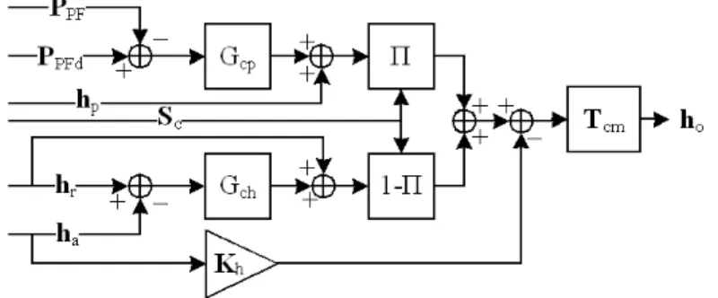
Hybrid control is a general approach that exhibits the combined advantages of impedance, admittance, and inertial-wrench control (or more precisely a null wrench control). The structure of the admittance/impedance hybrid control for one platform is shown in figure 4 and is detailed in figure 6. Two identical control structures are implemented, one per platform. The selection of the control class for each DOF of the platform is achieved by the П matrix. The state of the П matrix depends on the orientation of contact points geometry and the orientations of the platform.
When the reaction force hr is null and the impedance control class is selected by the П
matrix, one simply chooses a null force control scheme with an open gain loop Gch=K.
Otherwise, impedance or admittance control is applied on the desired DOF for each platform. Admittance control could be performed by velocity or position feedback which could produce different experimental results, as described in (Duchaine & Gosselin, 2007). The desired platform positions PPFd (or the desired velocities) are defined by the contact
points given by the Newton engine. As the strategy used by the Newton engine, a wrench
hp must be added to the admittance control to avoid any large penetration inside a virtual
object when a collision detection may have been missed because the refresh rate is not performed in time. This strategy also avoids the computation of a new set of contact points as the foot enters the object. In the Newton engine, the wrench hp is computed with an
impedance model of the object and must be controlled in the physics engine since the command is a null penetration for a rigid contact. From figure 6, the wrench T-Icmho to be
computed by the hybrid controller is defined by equations (5) to (8) :
T h-I ( (P P ) h ) cm o ΠGcp PFd PF p with, (5) (6) (7) (8) where Gcp is a standard filter that controls the desired position PPFd (or the desired velocity)
of the platform (PPF is the measured position), Qc is the rotation matrix between the
contact points reference frame Gc and the platform reference frame GPF. Q is the
rotation matrix between reference frame GPF and its global counterpart Gg, which is
(4)
where hc represents the forces and torques that are applied on a single platform (i.e. the
wrench applied by the cables on that platform), τi is the tension vector of the ith (of n) cable,
W is the pose-dependent wrench matrix computed by the platform Jacobian matrix that
links Cartesian to articular velocities, G is a weighting matrix with its diagonal elements such that gi = 1 for all i, where the mathematical derivation of (3) is presented in (Barrette &
Gosselin, 2005) and an application is described in (Perreault & Gosselin, 2008).
2.5 Human safety and security management plan
In the context of a human and a mechanism interacting within the same workspace, safety for human user is one of the utmost importance issues to be considered for avoiding accidents and injuries. The overall control algorithm process has a safety manager with an error handler that was designed with the help of a risk study. Each component of the software must have self-testing capabilities (or BIST for Build-In Self Test) for a general system test planning for the purpose of quality assurance (QA) and safety management. A Hardware-in-the-loop (HIL) simulator could be implemented as a way for running some parts of the BIST and partially control the platform. Documentations can be found in the IEEE 829 Standard for Software Test Documentation, CSA Z432-04 and ISO 14121. For Cable-Driven Mechanism applied to haptic applications, a minimum of four safety issues must be considered and documented:
1. Sensors reliability or fault tolerant (cable cut or failure by fatigue);
2. Mechanical interference like cable interference and platform interference with other parts of the mechanism or the user (Otis et al., 2009a);
3. Workspace limitations when the platform is going outside of its workspace; 4. Human and robot interaction like :
The mechanical device that safely disconnects the user from the mechanism when the mechanism is out of control (Lauzier & Gosselin, 2009) and,
The safety tether which maintains the equilibrium of the user when walking, falling or when the mechanism is out of control (Ottaviano et al., 2008), (Grow & Hollerbach, 2006).Other safety aspects of the system must also be guaranteed. For example, the system must manage any sensor destruction and limits on control values (cable length, maximal and minimal cable tension, maximal current send to the motor, maximum wrench generated from the physics engine, etc.). Finally, a watchdog timer is included to ensure that the control algorithm process is executed within the prescribed period of the periodic process within an error of 5%. This watchdog and the timing period are set using a hardware interrupt implemented on a data acquisition board that is independent from the software to avoid control failure and to ensure hard real-time response. For computing derivative and for reducing noise on this value, the algorithm should consider the time shift generated by
the latency (the 5% error on the prescribed period) of the OS context switching (or other process running).
3. Admittance/Impedance/Inertial-Wrench Hybrid Control
Hybrid control is a general approach that exhibits the combined advantages of impedance, admittance, and inertial-wrench control (or more precisely a null wrench control). The structure of the admittance/impedance hybrid control for one platform is shown in figure 4 and is detailed in figure 6. Two identical control structures are implemented, one per platform. The selection of the control class for each DOF of the platform is achieved by the П matrix. The state of the П matrix depends on the orientation of contact points geometry and the orientations of the platform.
When the reaction force hr is null and the impedance control class is selected by the П
matrix, one simply chooses a null force control scheme with an open gain loop Gch=K.
Otherwise, impedance or admittance control is applied on the desired DOF for each platform. Admittance control could be performed by velocity or position feedback which could produce different experimental results, as described in (Duchaine & Gosselin, 2007). The desired platform positions PPFd (or the desired velocities) are defined by the contact
points given by the Newton engine. As the strategy used by the Newton engine, a wrench
hp must be added to the admittance control to avoid any large penetration inside a virtual
object when a collision detection may have been missed because the refresh rate is not performed in time. This strategy also avoids the computation of a new set of contact points as the foot enters the object. In the Newton engine, the wrench hp is computed with an
impedance model of the object and must be controlled in the physics engine since the command is a null penetration for a rigid contact. From figure 6, the wrench T-Icmho to be
computed by the hybrid controller is defined by equations (5) to (8) :
T h-I ( (P P ) h ) cm o ΠGcp PFd PF p with, (5) (6) (7) (8) where Gcp is a standard filter that controls the desired position PPFd (or the desired velocity)
of the platform (PPF is the measured position), Qc is the rotation matrix between the
contact points reference frame Gc and the platform reference frame GPF. Q is the
rotation matrix between reference frame GPF and its global counterpart Gg, which is
be set high enough (bounded by the appropriate stability criteria) to reduce the errors caused by the dynamics and friction of the cable-driven platform and of the motorized reels. A transfer matrix Tcm is used for computing the output wrench at the centre of mass of the
platform since all haptic wrenches are under the foot and the OTD uses the centre of mass as its reference. Also, to prevent the platform form sticking to the contact point (i.e. when the hybrid control is oscillating between admittance and impedance), the action wrench ha is
added to the output of the hybrid controller with a gain Kh. This gain and the two Cartesian
controllers must consider the geometry of the mechanism and stability margins. In a Cable-Driven Mechanism, an anisotropy geometry could be designed and the control would need more energy in some DOF than other for obtaining the same transparency. Note that the initial conditions of the integrators and the filters inside both Gch and Gcp must be adjusted
for avoiding bouncing and instability. Furthermore, in some circumstances, kinematics and dynamics uncertainties must be considered in a hybrid control as described in (Cheah et al., 2003).
Fig. 6. Admittance/Impedance/Null Force Hybrid Control
The selection between control classes is achieved by the diagonal selection matrix Sc
(1 or 0 on the diagonal and other values are set to 0) and is evaluated in the contact point reference frame Gc. The values on the diagonal of matrix Sc depend on friction, contact
points geometry, and calibration based on experiments. A second selection matrix, Пo,
defined in equation (9), is used to compute the force at each contact point by selecting the DOF under constraint using the Force Optimization Problem (FOP) algorithm defined in section 5.2:
(9)
Thus, a 0 on the diagonal of matrix So allows a null force control by providing a
corresponding null component for the wrench in contact points reference frame Gc. These
two selection matrices (Sc and So) are thereby quite similar in function, albeit not identical.
4. Definition of the multi-contact points geometry
Since the control strategy exploits two physics engines (Newton engine and HDR), each engine can control a given platform's DOF either in admittance or in impedance simultaneously. The virtual object properties and the contact points geometry are the criteria that determine the appropriate control class using the selection matrix П that satisfies the following properties:
1. For a collision between a virtual foot model and a rigid virtual object for which a friction model is implemented, the selection could be based on the geometry described by the contact points between the virtual object and the virtual foot model;
2. To simulate friction, impedance control with force feedback could be chosen because there is a tangent force at the contact point reacting to an applied force from the user;
3. For compliant virtual objects, impedance control could be chosen and
4. Movement in free space could be simulated by a null force control, a special case of impedance control when some components of hr are equal to 0.
The favoured method used for selecting a given control class is a multi-contact points strategy (shown in figure 7) that emphasizes control advantages relating to the simulation of rigid virtual objects which includes a friction model. Contact points are computed as the minimum set of points that completely define the boundary of the intersection between a virtual foot model and a given virtual object. They are represented in the Newton engine in conjunction with a corresponding set of normal vectors. For a haptic foot platform, a set of points whose relative distances are within ten millimetres can be viewed by the control algorithm as a single point.
The multi-contat points strategy used in this case involves the direction of the user-applied wrench for each foot: if a component of the measured wrench ha is in the same direction as a
normal vector describing contact points geometry, which means that the user pushes on the virtual object, this direction (or DOF) is then constrained by admittance control for rigid virtual objects; otherwise either null force control is selected to simulate free movement (i.e. the contact point is eliminated) or impedance control is employed to simulate friction. In the case of a soft virtual object, impedance control is selected in the direction normal to the contact points geometry. In figure 7, the normal vector describing contact points geometry is along the zc axis.