Faculté de génie
Département de génie mécanique
Analyse et optimisation d'un cycle organique de
Rankine Intégré avec un éjecteur monophasé
Analysis and Optimization of an Organic Rankine
Cycle Integrated with One-Phase Ejector
Thèse de doctorat
Spécialité: génie mécanique
Doctoral Thesis Specialty: Mechanical Engineering
Payam Haghparast
Jury :
Mikhail Sorin (Supervisor)
Sébastien Poncet (Examiner)
Mathieu Picard (Examiner)
Mehdi Falsafioon (Examiner)
RÉSUMÉ
L’intérêt pour la récupération de chaleur à faible temperature a augmenté au cours des dix dernières années en raison de la préoccupation croissante face à la pénurie d'énergie et au réchauffement climatique. Etant donné que les cycles de production de vapeur classiques ne permettaient pas souvent de récupérer efficacement de la chaleur perdue de faible qualité, de nombreuses solutions nouvelles ont été suggérées afin de produire de l’électricité à partir des sources de chaleur à basse température, telles que le biogaz, la géothermie, le solaire, les gaz d'échappement, etc.
Parmi ceux-ci, les cycles de Rankine organiques (ORC) semblent être les procédés les plus prometteurs et les plus largement appliqués. Dans un tel système, le fluide de travail est un composant organique, mieux adapté que l'eau pour les faibles températures de source de chaleur. Contrairement aux cycles de puissance traditionnels, cette technologie permet aussi de générer de l'électricité à petite échelle. D'autre part, la faible efficacité du cycle de Rankine organique (ORC) avec une source de chaleur de faible teneur (LGHS) a limité son utilisation dans l'industrie. Afin d'augmenter la capacité et la performance de la puissance de sortie, une nouvelle structure du cycle de Rankine organique intégré à un éjecteur (EORC) a été proposée dans le cadre de ce projet. Les éjecteurs sont des dispositifs simples dans lesquels l’énergie d’un flux est utilisée pour entraîner et augmenter la pression d’un flux secondaire par mélange direct. Ils sont utilisés en raison de leur fonctionnement simple, de leur faible entretien et de l’absence de pièces mobiles. Étant donné que l'impact des caractéristiques de fonctionnement de l'éjecteur et de sa géométrie est important pour optimiser la conception d'un système EROC, trois documents publiés ont examiné en détail l'amélioration des performances de l'éjecteur. Dans un premier lieu, un modèle 1D d'éjecteur complet a été préparé en considérant la meilleure hypothèse de choc normal et le choix de l'efficacité locale qui constituent deux des plus grandes sources d'erreur dans les modèles 1D. Un grand nombre de simulations CFD ont été effectuées. Les résultats ont été validés et comparés avec d’autres modèles 1D et des données expérimentales, dans le but d’analyser les flux d'exergie interne d’un éjecteur et pour extraire les valeurs des efficacités isentropiques, polytropiques, une contre-pression critique et un rapport d'entraînement. Des études numériques et expérimentales sur les éjecteurs ont révélé que le remplacement des efficacités isentropiques par des efficacités polytropiques dans les modèles d'éjecteurs 1D fournit des résultats plus précis. Les rendements polytropiques permettent d’accéder plus précisément aux effets de la variation du rapport de pression sur les irréversibilités des processus d’accélération et de décélération. Il a été démontré que la déviation de la longueur de conduit à surface constante, calculée en utilisant un rendement isentropique par rapport à la longueur réelle, est trois fois supérieure à celle calculée en utilisant un rendement polytropique. De plus, des résultats expérimentaux ont montré que les meilleures performances de l'éjecteur et par conséquent du cycle étaient atteintes pour le rapport de pression maximal au point critique de la température du condenseur. A cette condition, les pertes d'exergie interne de l'éjecteur sont minimes selon les études numériques effectuées. Enfin, après une étude approfondie sur le comportement des éjecteurs, dans la quatrième publication, un éjecteur approprié (fonctionnant en régime de double étranglement) est utilisé pour améliorer les performances du EORC. Il a été démontré qu'une augmentation du rapport de la surface de l'éjecteur, du débit massique secondaire ainsi qu'une diminution du diamètre de la gorge et des propriétés de l'éjecteur d'entrée ont des effets significatifs sur l'augmentation de la puissance nette. En outre, il a été constaté que la production d'électricité est indépendante des paramètres de sortie de l’éjecteur en mode On-Design.
Mots-clés: Optimisation; Cycle organique de Rankine; Éjecteur; Modèle thermodynamique;
Abstract
The interest for low grade heat recovery has been growing for the last ten years because of the increasing concern over energy shortage and global warming. Since conventional steam power cycles cannot give a good performance to recover low grade waste heat, a large number of new solutions have been suggested to produce electricity from low-temperature heat sources such as biological waste heat, geothermal heat, solar thermal power, engine exhaust gases, domestic boilers, etc. Among them, the Organic Rankine Cycle (ORC) system seems to be the most promising process and it is the most widely applied. In such a system, the working fluid is an organic component, better adapted than water to lower heat source temperatures. Unlike traditional power cycles, local and small-scale power generation is made possible by this technology. On the other hand, the low efficiency of the Organic Rankine Cycle (ORC) with a low-grade heat source (LGHS) has limited its use in the industry. In order to increase the power output capacity and its performance, a new structure of the Organic Rankine Cycle integrated with Ejector (EORC) is proposed in this project. Ejectors are simple devices in which the energy of a flow is used to entrain and enhance the pressure of a secondary stream by direct mixing. They are used due to their simple operation, low maintenance requirements and lack of moving parts. Since the impact of ejector working characteristics and its geometry are important to optimize the design of an EROC system, three published papers have investigated in detail the improvement of ejector performance. In the first step, a comprehensive ejector 1D model is prepared by considering the best normal shock assumption and the selection of the efficiencies that are two of the greatest sources of error in the 1D models. A large number of CFD simulations have been performed for validating and comparing with 1D models and experimental data, for ejector internal exergy analysis, and to extract ejector isentropic and polytropic efficiencies, critical back pressure and entrainment ratio. Numerical and experimental investigations on the ejectors have revealed that the replacement of isentropic efficiencies with polytropic efficiencies within 1D ejector models provides more accurate results. Polytropic efficiencies access more precisely the effects of the pressure ratio variation on the irreversibilities of the acceleration and deceleration processes. It is demonstrated that the deviation in the constant area duct length, calculated by using an isentropic efficiency from the real length is three times greater than the one calculated by using a polytropic efficiency. Furthermore, from experimental results, it is found that the best performance of the ejector and consequently the cycle were achieved for the maximum pressure ratio at the critical condenser temperature point. At this condition, ejector internal exergy losses are minimal according to the carried out numerical studies. Finally, after a comprehensive study on the ejector behavior, in the fourth journal publication, an appropriate ejector (working in the double-choking regime) is employed to enhance the EORC performance. It is shown that a rise in the ejector area ratio, secondary mass flow rate as well as decreasing the throat diameter and inlet ejector properties have significant effects on increasing the net power output. It is further found that power output capacity is independent of the ejector outlet parameters in the on-design mode.
Keywords: Optimization; Organic Rankine Cycle; Ejector; Thermodynamic model; CFD
Acknowledgments
I would like to express my deep appreciation to my supervisor Prof. Mikhail Sorin, for his continued support, valuable guidance, and the academic environment he provided during the course of research. Without his support and encouragement, this thesis would not have been possible.
I would like to thank my committee members, Prof. Sébastien Poncet, Prof. Mathieu Picard and Dr. Mehdi Falsafioon for their time to review and approve my thesis.
I would like to thank Dr. Hakim Nesreddine and Dr. Marc A. Richard as my industrial advisors at Energy Technologies Laboratory (LTE) of Hydro-Québec for their support, valuable consultation and experimental tests during my research.
I am grateful to my friends and colleagues at the Université de Sherbrooke for providing a friendly and dynamic environment in the office. I have had a great time working with you guys and have enjoyed each and every one of you.
I would like to acknowledge my parents and my brothers for the unlimited love and support you provided me throughout all these years. Without your support, I would not have made it so far.
Last but not least, I am greatly indebted to my dear wife, Sahar, who has inspired me and supported me throughout this research.
TABLE OF CONTENTS
TABLE OF CONTENTS ... VI LIST OF FIGURES ... IX LIST OF TABLES ... XII
1 CHAPTER 1 : INTRODUCTION ... 1
1.1 BACKGROUND AND MOTIVATION ... 1
1.2 OBJECTIVES AND APPROACH ... 2
1.3 THESIS OUTLINE ... 2
2 CHAPTER 2 : STATE OF THE ART ... 4
2.1 ORGANIC RANKINE CYCLE (ORC) ... 4
2.1.1 Solar energy use ... 7
2.1.2 Geothermal systems ... 8
2.1.3 Biomass combined heat and power ... 9
2.1.4 Waste heat recovery ... 10
2.2 THE APPLICATION OF THE EJECTOR IN THE POWER CYCLES ... 12
2.2.1 The application of the ejector in the organic Rankine cycles ... 12
2.2.2 The application of the ejector in the cascade organic Rankine cycles ... 15
2.3 MODELING OF THE ONE-PHASE FLOW EJECTOR ... 17
2.4 GENERAL DEFINITION OF THE EJECTORS ... 19
3 CHAPTER 3 : EFFECTS OF COMPONENT POLYTROPIC EFFICIENCIES ON THE DIMENSIONS OF MONOPHASIC EJECTORS ... 25
3.1 ABSTRACT ... 26
3.2 INTRODUCTION... 28
3.3 EJECTOR OPERATION AND GEOMETRY... 31
3.4 DESCRIPTION OF THE MODELS ... 33
3.4.1 CFD model ... 33
3.4.1.1 Details of the CFD settings ... 33
3.4.1.2 Details of the mesh grid used in the CFD calculations ... 34
3.4.1.3 Calculation of the critical back pressure point (point cp) ... 35
3.4.1.4 Calculation of the polytropic efficiencies ... 37
3.5 1DTHERMODYNAMIC MODEL ... 39
3.5.1 Assumptions ... 39
3.5.2 Calculating procedure ... 40
3.6 RESULTS OF THE EFFECT OF POLYTROPIC EFFICIENCIES ... 43
3.7 PARAMETRIC STUDY ... 46
3.7.1 Effect of inlet and outlet pressures on ejector dimensions ... 47
3.7.2 Effect of polytropic efficiency values on ejector dimensions ... 48
3.7.3 Effect of mass flow rates on ejector dimensions ... 49
3.7.4 A summary of the results of the parametric study ... 50
3.7.5 Empirical correlations of the ejector component polytropic efficiencies ... 50
3.8 CONCLUSION ... 51
3.9 ACKNOWLEDGEMENTS ... 51
4 CHPATER 4 : THE IMPACT OF INTERNAL EJECTOR WORKING CHARACTERISTICS AND GEOMETRY ON THE PERFORMANCE OF A REFRIGERATION CYCLE ... 53
4.1 ABSTRACT ... 54
4.2 INTRODUCTION... 56
4.3.1 Ejector ... 60
4.3.2 Heat exchangers, feed pump and instruments ... 61
4.3.3 Measurement procedure ... 62
4.4 SYSTEM PERFORMANCE ANALYSIS ... 63
4.5 CFD MODEL ... 65
4.5.1 Numerical setup ... 65
4.5.2 Details of the geometry meshing ... 66
4.5.3 Validation of the CFD simulation ... 67
4.6 PERFORMANCE ANALYSIS UNDER VARIOUS OPERATING CONDITIONS ... 68
4.6.1 Effect of generator temperature ... 68
4.6.2 Effect of condenser temperature ... 71
4.6.3 Effect of primary mass flow rate ... 74
4.6.4 Effect of evaporator temperature ... 76
4.6.5 A summary of the obtained results of four cases ... 78
4.7 GEOMETRICAL IMPROVEMENT OF THE EJECTOR FOR INCREASING THE PRESSURE RATIO ... 81
4.7.1 Thermodynamic Model ... 82
4.7.2 Effects of the ejector dimensions on the ejector performance ... 82
4.8 CONCLUSIONS ... 84
4.9 ACKNOWLEDGEMENTS ... 85
5 CHAPTER 5 : EFFECT OF ASSUMPTIONS OF NORMAL SHOCK LOCATION ON THE DESIGN OF SUPERSONIC EJECTORS FOR REFRIGERATION ... 86
5.1 ABSTRACT ... 87
5.2 INTRODUCTION... 89
5.3 EJECTOR ANALYSIS PROCEDURE ... 90
5.4 EJECTOR OPERATION AND GEOMETRY ... 90
5.5 CFD MODEL ... 92
5.6 THERMODYNAMIC MODEL ... 94
5.7 RESULTS AND DISCUSSION... 97
5.8 CONCLUSION ... 99
5.9 ACKNOWLEDGEMENTS ... 100
6 CHAPTER 6 : ANALYSIS AND DESIGNOPTIMIZATION OF AN EJECTOR INTEGRATED INTO AN ORGANIC RANKINE CYCLE ... 101
6.1 ABSTRACT ... 102
6.2 INTRODUCTION... 103
6.3 THERMODYNAMIC MODELING AND ANALYSIS ... 106
6.3.1 ORC modeling ... 106
6.3.2 Ejector modeling ... 107
6.3.3 Exergy analysis ... 108
6.4 VALIDATION OF THERMODYNAMIC MODELS ... 109
6.4.1 Validation of the ORC model ... 109
6.4.2 Validation of the ejector model ... 110
6.5 SIZING AN EJECTOR FOR AVAILABLE ORC TEST BENCH ... 111
6.6 EVALUATION OF EORC SYSTEM FOR A FIXED EJECTOR PERFORMANCE ... 112
6.7 PARAMETRIC STUDY ... 114
6.7.1 Effect of ejector dimensions on EORC performance ... 114
6.7.2 Effect of ejector operating conditions on EORC performance ... 116
6.7.3 Effect of ejector polytropic efficiencies on EORC performance ... 118
6.7.4 Effect of expander inlet properties on the performance of EORC... 118
6.7.5 A summary of the results of the parametric study ... 119
6.8 CONCLUSION ... 120
7 CHAPTER 7 : CONCLUSION AND PERSPECTIVES ... 122
7.1 CONCLUSION ... 122
7.2 CONCLUSION (FRENCH) ... 124
7.3 PERSPECTIVES ... 126
LIST OF FIGURES
Figure 2.1 Working principle of an ORC cycle with (right) and without (left) recuperator [1] 5
Figure 2.2 ORC main components [1] ... 5
Figure 2.3 The schematic and Ts diagram of the organic Rankine cycle. ... 5
Figure 2.4 ORC applications to generate electricity from low-temperature heat sources [1]. ... 6
Figure 2.5 Working principle of a solar ORC system [2]. ... 8
Figure 2.6 Working principle of a geothermal ORC system [1]. ... 9
Figure 2.7 Working principle of a biomass CHP ORC[1]. ... 10
Figure 2.8 Energy flow as a function of the conversion temperatures in a biomass CHP ORC system [1]. ... 10
Figure 2.9 (a) Principle of Organic Rankine Cycle with Ejector (EORC) (b) Principle of double Organic Rankine Cycle (DORC) [15]. ... 13
Figure 2.10 Experiment system of Organic Rankine Cycle with Ejector (EORC). ... 13
Figure 2.11 Schematic diagram of the Kalina cycle with ejector (EKalina cycle) [17]... 14
Figure 2.12 Schematic diagram of the combined ORC and refrigeration cycle [19]. ... 15
Figure 2.13 Schematic of the combined ORC and absorption refrigeration system [20]. ... 16
Figure 2.14 Schematic diagram of the proposed DEDS system [22]. ... 17
Figure 2.15 Schematic of an ejector ... 19
Figure 2.16 Variation in stream pressure and velocity as a function of location along the ejector [41] ... 20
Figure 2.17 Ejector operation regimes for constant inlet conditions[42]. ... 20
Figure 2.18 Typical ejector operating map: ωas a function of inlet and outletpressures[43]. ... 21
Figure 2.19 Two different types of ejectors based on nozzle exit position (NXP)[40]. ... 21
Figure 2.20 Definition of polytropic and isentropic efficiencies for the acceleration of the primary fluid [36] ... 23
Figure2.21 Choked flows in the constant area mixing ejector (Mach contour) ... 24
Figure2.22 Choked flows in the constant pressure mixing ejector (Mach contour) ... 24
Figure 2.23 Hypothetical throat area (effective area) for the secondary flow [46]. ... 24
Figure 3.1 The schematic diagram of the ejector refrigeration system. ... 29
3.2 Definitions of polytropic (or elemental) and isentropic (or overall) efficiencies to calculate the flow properties. ... 30
Figure 3.3 Ejector geometry, parts and main cross-sections ... 31
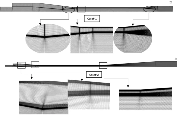
3.5 Variation of axial Mach number with different grid levels for Case# 1 & 2 ... 34
Figure 3.6 Details of the mesh grid used in the CFD calculations for Case# 1 (CAM) and Case# 2 (CPM) ... 35
Figure 3.7 Ejector operational modes (Performance Curves) for Case# 1 (R245fa) ... 36
Figure 3.8 Ejector operational modes (Performance Curves) for Case# 2 (R141b) ... 36
Figure 3.9 Mach number plots at three different back pressures for case# 1 ... 37
Figure 3.10 Mach number plots at three different back pressures for case# 2 ... 37
Figure 3.11 Definitions of the elemental process (polytropic) in the CFD model for Case# 1&2 ... 38
Figure 3.12 Calculation Procedure of ejector dimensions and operating conditions. ... 43
Figure 3.13 Comparisons of dimensions for case# 1 (CAM) ... 44
Figure 3.14 Comparisons of dimensions for case# 2 (CPM) ... 45
Figure 4.1 Schematic diagram of the ejector refrigeration system (ERS)... 59
Figure 4.2 P-h diagram of the ejector refrigeration system (ERS). ... 59
Figure 4.3 Experimental set up of the ejector refrigeration system (ERS). ... 60
Figure 4.4 (a) Ejector geometry, parts and main cross-sections (b) the general view of the tested ejector ... 61
Figure 4.5 Variation of the axial Mach number with different grid levels ... 67
Figure 4.6 Details of the mesh grid used in the CFD calculations ... 67
Figure 4.7 Ejector operational moods (Performance Curves) (𝑇𝑔 = 80 °𝐶 , 𝑇𝑒 = 30 °𝐶 , 𝑚𝑝𝑟 = 0.33 𝑘𝑔/𝑠) ... 68
Figure 4.8 Effects of generator temperature (Tg) (a) on the coefficient of performance (COP) and component ejector efficiencies (b) on the entrainment ratio and ejector exergy losses at fixed operating conditions (𝑇𝑐 = 20 °𝐶 , 𝑇𝑒 = 20 °𝐶 , 𝑚𝑝𝑟 = 0.33 𝑘𝑔/𝑠) ... 70
Figure 4.9 Comparisons between the different generator temperatures (Tg) for exergy destruction index ξ and Mach number contour within the ejector for case# 1. ... 71
Figure 4.10 Effects of condenser temperature (Tc) (a) on the coefficient of performance (COP) and component ejector efficiencies (b) on the entrainment ratio and ejector exergy losses at the fixed operating conditions (𝑇𝑔 = 80 °𝐶 , 𝑇𝑒 = 30 °𝐶 , 𝑚𝑝𝑟 = 0.33 𝑘𝑔/𝑠) ... 73
Figure 4.11 Effects of ejector back pressure (P1) on the pressure ratio (PR) and on the entrainment ratio (ω) at the fixed operating conditions (𝑇𝑔 = 80 °𝐶 , 𝑇𝑒 = 30 °𝐶 , 𝑚𝑝𝑟 = 0.33 𝑘𝑔/𝑠) ... 73
Figure 4.12 Comparisons between the different condenser temperatures (Tc) for exergy destruction index ξ and Mach number contour within the ejector for case# 2. ... 74
Figure 4.13 Effects of primary mass flow rate (𝑚𝑝𝑟) (a) on the coefficient of performance (COP) and component ejector efficiencies (b) on the entrainment ratio and ejector exergy losses at fixed operating conditions (𝑇𝑔 = 90 °𝐶 , 𝑇𝑐 = 20 °𝐶 , 𝑇𝑒 = 20 °𝐶 ) ... 75
Figure 4.14 Comparisons between the different primary mass flow rates (𝑚𝑝𝑟) for exergy
destruction index ξ and Mach number contour within the ejector for case# 3. ... 76
Figure 4.15 Effects of evaporator temperature (Te) (a) on the coefficient of performance (COP) and component ejector efficiencies (b) on the entrainment ratio and ejector exergy losses at fixed operating conditions (𝑇𝑔 = 85 °𝐶 , 𝑇𝑐 = 22 °𝐶 , 𝑚𝑝𝑟 = 0.33 𝑘𝑔/𝑠) ... 77
Figure 4.16 Comparisons between the different evaporator temperatures (Te) for exergy destruction index ξ and Mach number contour within the ejector for case# 4. ... 77
Figure 4.17 Total exergy destruction versus mixing efficiency. ... 79
Figure 4.18 Overall ejector efficiency versus COP ... 80
Figure 4.19 Ejector exergy efficiency versus COP ... 81
Figure 5.1 Procedure for the optimization of calculating ejector parameters based on normal shock assumptions ... 90
Figure 5.2 Ejector geometry, parts and main cross-sections ... 91
Figure 5.3 Overall procedure for calculating the inputs and outputs ... 92
Figure 5.4 Details of the mesh grid used in the CFD calculations for Case# 1 (CAM) ... 93
Figure 5.5 Details of the mesh grid used in the CFD calculations for Case# 2 (CPM) ... 93
Figure 5.6 Mach number plots of the ejectors at various back pressures for case# 1 and case# 2 ... 94
Figure 5.7 Comparisons of dimensions for case 1 (CAM) ... 98
Figure 5.8 Comparisons of dimensions for case 2 (CPM) ... 99
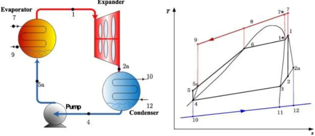
Figure 6.1 (a) the principle of the organic Rankine cycle with and without ejector and (b) corresponding T-s diagrams ... 104
Figure 6.2 Ejector geometry, parts, and main cross-sections ... 108
Figure 6.3 Comparisons of calculated dimensions with experimental geometry... 111
Figure 6.4 Comparison between ORC and EORC performance ... 114
Figure 6.5 Effects of ejector diameters on power output capacity ... 116
Figure 6.6 Effects of inlet ejector properties on power output capacity ... 117
Figure 6.7 Effects of ejector back pressure and secondary mass flow rate on power output capacity ... 117
Figure 6.8 Effects of ejector polytropic efficiencies on power output capacity ... 118
LIST OF TABLES
Table 3.1Operating conditions ... 32
Table 3.2 Geometry of the ejectors (Case# 1 & 2) ... 33
Table 3.3 CFD Settings (Case# 1 & 2) ... 34
Table 3.4 Efficiencies obtained from the CFD models for varying PR=P1/P6 (P6=100.1 kPa). (Case# 1) ... 38
Table 3.5 Efficiencies obtained from CFD models for varying PR=P1/P6 (P6=39.9 kPa), (Case# 2) ... 38
Table3.6 Effect of polytropic and isentropic efficiencies on ejector dimensions for ... 44
Table 3.7 Effect of polytropic and isentropic efficiencies on ejector dimensions ... 45
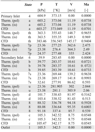
Table 3.8 Flow properties at different ejector cross-sections for the critical back pressure point for case 1 (CAM) (Pcp=190.19 kPa) ... 46
Table 3.9 Flow properties at different ejector cross-sections for the critical back pressure point for case 2 (CPM) (Pcp=105.5 kPa) ... 46
Table 3.10 Operating conditions ... 46
Table 3.11 Effects of the inlet and outlet pressures on the ejector dimensions ... 48
Table 3.12 Effects of the polytropic efficiencies on the ejector dimensions ... 49
Table 3.13 Effects of the mass flow rates on the ejector dimensions ... 49
Table 3.14 A summary of the results of the parametric study ... 50
Table 3.15 Ejector polytropic efficiencies regressing equations. ... 51
Table 4.1 steady state operating conditions of a reference case (𝑇𝑔 = 80 °𝐶 , 𝑇𝐶 = 24 °𝐶 𝑇𝑒 = 30 °𝐶 , 𝑚𝑝𝑟 = 0.33 𝑘𝑔/𝑠) ... 62
Table 4.2 Operating conditions (glycol inlet temperatures in heat exchangers and ejector primary mass flow rate) ... 63
Table 4.3 Operating conditions (evaporating, condensing, boiling temperatures and ejector primary mass flow rate) ... 63
Table 4.4 CFD Settings ... 66
Table 4.5 Effects of generator temperature (Tg) on ejector working characteristics at fixed operating conditions (𝑻𝒄 = 𝟐𝟎 °𝐂 , 𝑻𝒆 = 𝟐𝟎 °𝐂 , 𝒎𝒑𝒓 = 𝟎. 𝟑𝟑 𝐤𝐠/𝐬)... 70
Table 4.6 Effects of condenser temperature (Tc) on ejector working characteristics at fixed operating conditions (𝑻𝒈 = 𝟖𝟎 °𝐂 , 𝑻𝒆 = 𝟑𝟎 °𝐂 , 𝒎𝒑𝒓 = 𝟎. 𝟑𝟑 𝐤𝐠/𝐬) ... 72
Table 4.7 Effects of primary mass flow rate (𝒎𝒑𝒓) on ejector working characteristics at fixed
operating conditions (𝑻𝒈 = 𝟗𝟎 °𝐂 , 𝑻𝒄 = 𝟐𝟎 °𝐂 , 𝑻𝒆 = 𝟐𝟎 °𝐂 ) ... 75
Table 4.8 Effects of evaporator temperature (Te) on ejector working characteristics at fixed operating conditions (𝑻𝒈 = 𝟖𝟓 °𝐂 , 𝑻𝒄 = 𝟐𝟐 °𝐂 , 𝒎𝒑𝒓 = 𝟎. 𝟑𝟑 𝒌𝒈/𝒔) ... 76
Table 4.9 A summary of the relationship between refrigeration cycle parameters and the ejector working characteristics ... 79
Table 4.10 Optimum operating conditions at the critical ... 82
Table 4.11 Effects of the ejector dimensions on the pressure ratio at the fixed entrainment ratio for the optimum operating condition. ... 84
Table 4.12 A summary of the relationship between ejector dimensions ... 84
Table 5.1 Operating condition ... 91
Table 5.2 Geometry of the ejectors (Case# 1 & 2) ... 91
Table 5.3 CFD Settings (Case# 1 & 2) ... 93
Table 5.4 Efficiencies according to the CFD models for critical back pressure point for case 1 and 2. ... 94
Table 5.5 Effect of the assumed normal shock location on ejector dimensions ... 98
Table 5.6 Effect of the assumed normal shock location on flow properties ... 98
Table 5.7 Effect of the assumed normal shock location on ejectordimensions for ... 98
Table 5.8 Effect of the assumed normal shock location on flow ... 99
Table 6.1 Comparison between ORC simulation and experimental data for different cases ... 110
Table 6.2 Comparison between dimensions calculated by ... 111
Table 6.3 The geometry of the designed ejector for ORC base case ... 112
Table 6.4 Simulation conditions of the EORC system. ... 112
Table 6.5 Performance comparison between EORC with ORC in the condition of the same outlet point from the first-stage evaporation. ... 113
Table 6.6 Effects of ejector dimensions on EORC performance. ... 115
Table 6.7 Effects of ejector operating conditions on EORC performance. ... 116
Table 6.8 Effects of the polytropic efficiencies on EORC performance... 118
Table 6.9 Effects of the expander inlet properties on EORC performance. ... 119
1
CHAPTER 1 : INTRODUCTION
1.1
Background
and motivation
Significant growth in energy demand over the past years has caused an energy crisis in the world. On the other hand, there is a vast amount of the low-temperature waste heat generally discharged during various industrial processes which is usually released to the environment directly. Therefore, recovering these low-grade heat sources can achieve energy saving, sustainable development and also the reduction of environmental problems such as ozone depletion, global warming and air pollution. The organic Rankine cycle (ORC) is an effective method to recover the low-grade heat source by employing organic working fluids instead of water.
The ORC technology has been investigated widely during the past decades, and main efforts have been devoted to identify the working fluids in ORC systems and conduct performance optimizations. However, the low efficiency of the ORC has caused its application become limited in the industry. In this study, a new structure of the Organic Rankine Cycle integrated with an ejector (EORC) is proposed in order to increase the power output capacity and its performance.
Although an abundant literature is available on the optimization of ORCs, few papers propose a detailed modeling of the combination of this cycle with ejector. Thus because of this limited knowledge about this new ejector system, obtaining an optimum design methodology has received much attention from many researchers. Since ejector is a key component in the EORC system, it is important to quantify its performance in the cycle.
This study aims at proposing a detailed model of an ORC integrated with ejector including thermodynamic model, CFD and Experimental analysis. The validated thermodynamic model of EORC is eventually used to optimize the performance of the Cycle.
In general, this thesis will present an optimization study and detail investigation of an ORC system with ejector.A single-phase ejector model has been developed and incorporated into an ORC system to reveal the effects of various parameters such as operating conditions and ejector
geometry in the whole system. A thermodynamic modeling of single-phase ejector has been
used to release an optimum design. An experimental study is carried out to provide a validation of the analytical results. Furthermore, parametric study and optimization have been performed based on the obtained model to determine which design parameters have the most effects on the objective indicators.
1.2
Objectives and approach
The main objective of the project is the analysis and optimization of an ORC system integrated with ejector and compare to classical ORC system performance. To this end, the working characteristics and geometry of an ejector are investigated in order to have a more efficient design of ejector and consequently to improve the performance of the EORC system. This general objective includes the following specific objectives:
Develop a CFD model of the one-phase ejector to analyze the behavior of streams inside the ejector as well as calculating isentropic and polytrophic efficiencies, critical back pressure, entrainment ratio , and internal exergy losses.
Develop a 1-D thermodynamic model of a one-phase ejector to predict the performance of an ejector under different operating conditions and geometry parameters.
Perform an experimental analysis of an Organic Rankine Cycle (ORC) to validate thermodynamic simulation of the ORC.
Thermodynamic simulation of the ORC including heat exchangers, pump and turbine. Perform an experimental study of an R245fa single-phase ejector to validate the
thermodynamic and CFD models of a one-phase ejector.
Investigation on the more appropriate place of normal shock assumption and the selection of the ejector efficiencies that are two of the greatest sources of error in the ejector 1D models.
Perform a parametric study and optimization of the EORC to define the optimal values of ejector input parameters as well as its optimal design characteristics and geometry.
1.3
Thesis outline
The present thesis is divided into seven chapters. Chapter 1 is an introduction to the study. In chapter 2 a comprehensive literature review on ORC systems, some power and refrigeration cycles which are integrated with ejector, and operation and performance characteristics of the ejectors are presented.
As previously proven, the normal shock assumption and the selection of the efficiencies are two of the greatest sources of error in the 1D models. Since, in chapters 3 and 5, the impact of these key parameters are investigated. However, in chapter 4, the main focus is only on the investigation of the internal ejector working characteristics.
In chapter 3, a 1D model is proposed that is more realistic than previous 1D models due to the application of the polytropic (or elemental) efficiency conception. In this case, the 1D model is
able to consider the effects of the pressure ratio on the entropy increase during the irreversible acceleration and deceleration processes, unlike previous models, which use isentropic (or overall) efficiencies for this purpose. CFD simulation is used for calculating the real values of the polytropic efficiencies for the 1D model. In general, a comprehensive comparison between all dimensions obtained by the 1D model based on isentropic and polytropic efficiencies is carried out against experimental data. Empirical correlations for polytropic efficacies are also proposed using a parametric study.
In chapter 4, an experimental investigation is carried out in order to study the performance of an ejector refrigeration system (ERS) under various internal ejector working characteristics for both single-choking and double-choking regimes. A geometrical optimization of the ejector for increasing the pressure ratio and ejector performance is carried out.
In chapter 5, the effects of the normal shock assumption on the ejector dimensions are evaluated. The obtained dimensions by the 1D model based on different normal shock locations are compared to experimental data in order to determine more accurate assumption.
Finally, the main objective of the thesis is investigated in chapter 6. The performance of the EORC system is evaluated. For available ORC test bench, a one-phase ejector that works in the on-design regime is designed. The influence of ejector working characteristics and its geometry on the EORC system performance is investigated in order to have a more efficient system. A summary of important conclusions as well as the future works of this study are expressed in chapter 7. At last, all used references are given at the end of the thesis
2
CHAPTER 2 : STATE OF THE ART
This chapter summarizes an overall review of various articles related to the Organic Rankine Cycle (ORC), ejector and also some power and refrigeration cycles integrated with ejector. To better understanding of the previous works, it is divided into four main sections: the first section describes the organic Rankine cycle (ORC). In the second section, application of the ejector in the power cycles is investigated. In the third section, the modeling of the one-phase flow ejector is presented including CFD, experimental and thermodynamic models and lastly in the fourth section, a general definition of ejectors and some parameters which have important effects on its performance is introduced.
2.1 Organic Rankine Cycle (ORC)
Due to the scarcity of fossil fuels, environmental pollution and global warming in the past few decades, energy and environment have progressively attracted the world’s attention. The interest for energy saving and renewable energy have been growing in many parts of the world.
An important number of new solutions have been proposed to generate electricity from low-temperature heat sources and are now applied to many diversified fields such as solar thermal power, biological waste heat, engine exhaust gases, domestic boilers, etc. In general, more than 11% of total energy production is related to these sources [1].
The Organic Rankine Cycle (ORC) system is more common among other proposed solutions due to the simplicity and availability of its components. In the most organic Rankine cycles, a refrigerant undergoes phase transitions from a liquid to a gas and back again. Due to the lower boiling point and high heat transfer rate, the refrigerants are suitable for low-temperature heat sources.
The configuration of the Organic Rankine Cycle is somewhat simpler than that of the steam
Rankine cycle: there is no water-steam drum connected to the boiler and one single heat exchanger can be used to perform the three evaporation phases (preheating, vaporization and superheating). The variations on the cycle architecture are also more limited: reheating and turbine bleeding aregenerally not suitable for the ORC cycle, but a recuperator can be installed asa liquid preheater between the pump outlet and the expander outlet, asillustrated in figure 2-1[1]. The configuration of the ORC main components is based on figure 2-2.
Figure 2.1 Working principle of an ORC cycle with (right) and without (left) recuperator [1]
Figure 2.2 ORC main components [1]
The schematic and T-s diagram of an organic Rankine cycle is illustrated in figure 2-3.
The basic cycle is very similar to the traditional steam cycle: the organic working fluid is successively pumped, vaporized, expanded and thencondensed. The cycle with recuperator takes profit of the residual heat afterthe expansion to preheat the liquid after the pump. This operation allowsreducing the amount of heat needed to vaporize the fluid in the evaporator [1].
Unlike traditional power cycles, local and small-scale power generations are made possible by this technology. A wide range of ORC applications has been investigated in the previous works [1][2]. It should be mentioned that Organic Rankine Cycle (ORC) is a technology that can convert thermal energy at relatively low temperatures in the range of 80 to 350 °C to electricity and can, therefore, play an important role to improve the energy efficiency of new or existing applications. Figure 2-4 illustrates some applications of such a system. A survey on the progress of the ORC technology over the last decades, for commercial applications, shows that total installed capacity is about 2749.1 MWel, in 563 power plants by 2017 and new capacity planned is more than 523.6 MWel in 75 plants. Geothermal power plants contribute to 76.5% of all ORC installed capacity in the world. Biomass follows with 10.7%. Heat recovery from gas turbines (compressor stations along pipelines) and stationary diesel power plants have a similar share with 8.5%. All other heat recovery applications represent 4.2%, while solar thermodynamic remains neglectible. ORMAT is the world leader for the total installed capacity (65.7%), followed by the Italian companies Turboden (12.6%) and Exergy (9.8%) [1].
2.1.1 Solar energy use
Integrated solar combined cycles with ORC are currently used in countries with high incident solar radiation in order to increase the net output power and decrease the specific fuel consumption. Solar power is known as a renewable free source of energy that is sustainable and totally inexhaustible, unlike fossil fuels that are limited.
Solar power is the conversion of sunlight into electricity, either directly using photovoltaics (PV), or indirectly using concentrated solar power. Concentrated solar power systems use lenses or mirrors and track systems to focus a large area of sunlight into a small beam. The sun is tracked and reflected on a linear or a punctual collector, transferring heat to a fluid at high temperature. The heat is then transferred to a power cycle generating electricity. The three main concentrating technologies are the parabolic dish, the solar tower, and the parabolic trough. Parabolic dishes and solar towers are punctual concentration technologies leading to a higher concentration factor and higher temperatures. The best-suited power cycles for these technologies are the Stirling engine (for small-scale plants), the steam cycle or even the combined cycle for solar towers [3].
Parabolic troughs work at a lower temperature (300°C to 400°C) than point-focused CSP systems. They are basically coupled to the conventional steam Rankine cycles to generate power [4]. Organic Rankine cycles are a favorable technology to reduce investment costs at small scale: they can work at lower temperatures and the total installed power can be reduced down to the kW scale. The working principle of such a system is presented in figure 2-5.
Shaaban [5] recently described a modified integrated Solar Combined Cycles (ISCC) with an Organic Rankine Cycle ORC. The ORC was used in order to intercool the compressed air and generate a net power from the received thermal energy. The performance of the proposed cycle was optimized. Fifteen working fluids were studied in the ORC. The working fluid R1234ze(z) shows a good agreement between thermodynamics, economic, safety and environmental considerations. An increase of the output power by 19.5% with solar contribution and 23.1% without solar contribution have been shown for the cycle with R1234ze(z).
Quoilin et al. [2] described the design of a solar organic Rankine cycle being installed in Lesotho for rural electrification purpose. The model allows sizing the different components of the cycle and evaluates the performance of the system. They compared different working fluid and two simulated different expansion machine configurations are simulated (single and double stage).
Technologies such as Fresnel linear concentrators [6] are particularly appropriate for solar ORCs since they require lower investment cost but work at a lower temperature.
Figure 2.5 Working principle of a solar ORC system [2].
2.1.2 Geothermal systems
The ground and lakes around us represent a vast reservoir of renewable thermal energy stored from the sun. This geothermal energy is estimated to exceed all other energy sources combined by more than two thousand times. At depths below 8 to 10 feet (2.5 to 3 meters), the earth's temperature remains at or near the average annual air temperature. Geothermal heat sources are available over a broad range of temperatures, from a few tens of degrees up to 300°C. The actual technological lower bound for power generation is about 80°C. Below this temperature conversion efficiency becomes too small and geothermal plants are not economical [3].
To recover heat at an acceptable temperature, boreholes must generally be drilled in the ground, for the production well and for the injection well (fig. 2-6). The hot brine is pumped from the former and injected into the latter at a lower temperature. Depending on the geological formation, boreholes can be several thousand meters deep which are required. According to Kranz S. (2007), this leads to a high share of drilling cost in the total investment cost (up to 70%) of a geothermal ORC plant. Lazzaretto et al. [8] reported a much more moderate share of 15.6% for an Italian geothermal binary cycle.
Figure 2.6 Working principle of a geothermal ORC system [1].
2.1.3 Biomass combined heat and power
Biomass is a renewable energy source not only because the energy in it comes from the sun, but also because biomass can regrow over a relatively short period of time compared with the hundreds of millions of years that it took for fossil fuels to form. Biomass is widely available in a number of agricultural or industrial processes such as wood industry or agricultural waste. Among other devices, it can be converted into electricity by combustion through a thermodynamic cycle.
In small biomass plants, the ORC is the ideal choice due to its efficiency, availability and ability to follow load dependent on fuel supply. In addition, the elimination of the steam turbine for traditional biomass solutions brings with it a number of maintenance and operational advantages.
The boiler through the combustion process converts the biomass in thermal power to feed the ORC module. The hot exhaust gas warms up the intermediate fluid in a heat exchanger. The ORC-boiler interface circuit transfers the thermal power from the boiler to the ORC evaporator. The commonly employed intermediate fluids between the boiler and ORC are thermal oil, pressurized water and steam. The interface fluid transfers heat to the organic fluid in the ORC evaporator, where the organic fluid vaporizes. The vaporized fluid then passes to the turbine. Here the expansion vapor causes the turbine to spin and creates electricity into the generator. Figure 2-7 illustrates the working principle of a biomass CHP ORC [1].
Moro et al. [9] investigated biomass CHP plants in order to achieve high energy conversion efficiency. It is shown that the biomass CHP plants are usually driven by the heat demand rather than by the electricity demand. Figure 2-8 shows energy flow as a function of the conversion temperatures in a biomass CHP ORC system.
Figure 2.7 Working principle of a biomass CHP ORC[1].
Figure 2.8 Energy flow as a function of the conversion temperatures in a biomass CHP ORC system [1].
2.1.4 Waste heat recovery
One of the most important solutions for energy production is to recover waste heats. The waste heat from industrial plants, mechanical equipment and internal combustion engines are the forms of essentially free energy which can be recovered and converted into work and electricity. Organic Rankine Cycle (ORC) is a technology ideally suited for such heat sources to generate electricity.
- Heat recovery on mechanical equipment and industrial processes
Many applications in the manufacturing industry reject heat at relatively low temperature. It is quite abundant and widely available but its quality is low compared to that of conventional fossil-fuel power-plants and cannot, therefore, be converted into electricity using water as the working fluid. On the other hand, in the most power plants and manufacturing plants, such heat doesn’t reuse on-site and it is rejected to the atmosphere. But, it leads to generate health or environmental issues that are due to pollutants (CO2, NOx, SOx, HC) contained in the flue gases. Besides, the heat rejection can perturb aquatic equilibrium and have a negative effect on the biodiversity. Therefore, the recovery of this heat is necessary [10].
Bailey and Worrell )2005) investigated the potential of such cycles. A potential of 750 MWe is estimated for power generation from industrial waste heat in the US, 500 MWe in Germany and 3000 MWe in Europe (EU-12) [11].
Engin and Ari (2005) presented the cement industry has a high potential among other industries for waste heat recovery because 40% of the heat is lost in flue gases. These flue gases are located after the limestone preheater or in the clinker cooler, with a temperature varying between 215 and 315 °C [12].
Minea [13] investigated on a laboratory beta-prototype, 50 kW Organic Rankine Cycle (ORC) machine using industrial waste. He showed that the power generated and the overall net conversion efficiency rate of the machine mainly depends on the inlet temperatures of the waste heat and cooling fluid as well as on the control strategy and amount of parasitic electrical power required.
- Heat recovery on internal combustion engines
The Internal Combustion Engine (ICE) has been a primary power source for automobiles, long-haul trucks, locomotives, and ships over the past century. An Internal Combustion Engine only converts about one-third of the fuel energy into mechanical power. The heat recovery Rankine cycle system is efficient means for recovering heat (in comparison with other technologies such as thermo-electricity and absorption cycle air-conditioning). The idea of associating a Rankine cycle to an ICE is not new and the first technical developments followed the 70’s energy crisis. Sprouse and Depcik (2013) reviewed the history of internal combustion engine exhaust waste heat recovery focusing on Organic Rankine Cycles since this thermodynamic cycle works well with the medium-grade energy of the exhaust [14]. The choice of the working fluid and the cycle expander were the main subjects of this review due to the significant influence on system performance. The results showed a potential fuel economy improvement around 10% with modern refrigerants and advancements in the expander technology.
2.2 The application of the ejector in the power cycles
Since 1858, ejectors have been intensively studied for a large number of various applications. In the past, ejectors have mostly been used in different cycles for refrigeration purposes. In recent decades, they are widely used in the power cycles.
The number of the investigation on the ORC integrated with the ejector is very limited. While the investigation on cascade organic Rankine cycles is abundant. The review of the application of the ejector within power cycles is divided into two different sections.
2.2.1
The application of the ejector in the organic Rankine cycles
Scientific literature covering organic Rankine cycle integrated with ejector is still limited, as a few investigations have been carried out on such cycles. The research on ORC is mainly reflected in the selection of working fluids, analysis of the thermal performance, optimization of the system and transcritical cycle. The selection of the working fluids greatly affects the thermal performance of the ORC, the power output capacity and the thermal efficiency.
In order to increase the power output capacity and efficiency, some researchers have proposed an integration of ORC with ejector.
Li et al. (2012) proposed a combined ORC with ejector. In this new configuration, an ejector and a second-stage evaporator were added to the ORC [15]. Figure 2-9 (a) and figure 2-9 (b) illustrates the principle of the organic Rankine cycle with ejector (EORC) and the principle of double Organic Rankine Cycle (DORC) respectively. The vapor from the second-stage evaporator was worked as the primary fluid for the ejector to suck the exhaust from the expander to decrease the expander backpressure and increase the pressure difference through the expander which resulted in an increase of the power output capacity compared to ORC.
Figure 2.9(a) Principle of Organic Rankine Cycle with Ejector (EORC) (b) Principle of double Organic Rankine Cycle (DORC) [15].
Their experiments (Figure 2-10) and theoretical analyses were carried out in the same operation conditions. The ejector in EORC made the expander’s outlet pressure decreased by 0.32 bar compared to the ORC system, which meant that the output capacity was increased by 34.93%. The output efficiency of EORC was 5.93%, increased by 26.17% compared to ORC’s 4.70%, but the system efficiency of EORC was lower than that of ORC.
Figure 2.10 Experiment system of Organic Rankine Cycle with Ejector (EORC).
Li et al. [16] calculated the net power output and exergy destruction of three cycles (ORC, EORC, DORC). The results show that the power output is higher in the EORC and DORC compared to the ORC. The power output and thermal efficiency of the DORC are superior to the EORC, but another expander-generator and its auxiliary equipment are required for the DORC led to the increase of the investment and operation management compared to the EORC.
They also ranked the exergy loss ratio in the evaporator and the condenser of the cycles from high to low is: EORC > DORC > ORC and it is: ORC > DORC > EORC in the exhaust water. The cycle’s exergy efficiency can be ranked from high to low: DORC > EORC > ORC. Another important result of their research is the most exergy losses took place in the evaporator, condenser and the exhaust water, cycle at the maximum net power output while it is the smallest in the ejector in the EORC.
Li et al. [17] also proposed a Kalina cycle with ejector. Kalina cycle and organic Rankine cycles (ORC) are potentially feasible to recover energy from the low-grade heat sources (LGHS). Results show that the net power output and thermal efficiency of the EKalina cycle are higher than that of the KCS.
Figure 2.11 Schematic diagram of the Kalina cycle with ejector (EKalina cycle) [17].
Li et al. [18] proposed a supercritical or transcritical Rankine cycle with ejector (ESRC, ETRC) based on the basic supercritical or transcritical Rankine cycle (SRC, TRC) in order to generate electricity from low-grade sources. They increased the net power output of the cycle by decreasing the outlet pressure of the expander or increasing the pressure difference in the expander. The carbon dioxide was chosen as the working fluid for the cycles. Water was chosen as the fluid of the low-grade heat Results show that the net power output of the cycles could be ranked from high to low: ESRC > ETRC > SRC > TRC, and the thermal efficiency could be ranked from high to low: TRC > SRC > ESRC > ETRC.
2.2.2
The application of the ejector in the cascade organic Rankine cycles
Ejectors have long been used in power and cooling applications and as vacuum generators. A large number of researchers have investigated various cascade cycles. In this part will have a review of some studies related to cascade organic Rankine cycles.
Habibzadeh et al. [19] performed a thermodynamic study of a thermal system which combines an organic Rankine cycle (ORC) and an ejector refrigeration cycle (Figure 2-12). The results for refrigerants under investigation show that when the heat source temperature increases the thermal efficiency and the total exergy destruction increase while the total thermal conductance decreases. By increasing the cooling water temperature, the total exergy destruction decreases while the total thermal conductance increases. When the expansion ratio of the turbine increases the total exergy destruction and the total thermal conductance decrease.
By varying either the inlet pressure of the pump (or equivalently the evaporation temperature) or the inlet pressure of the turbine more results could be achieved. They revealed that these variables can be optimized to obtain a minimum total thermal conductance. R601a has the highest thermal efficiency and lowest total exergy destruction in both optimum cases. Among the considered working fluids, R141b has the lowest optimum pressure and smallest total thermal conductance for both these optimum conditions.
Figure 2.12 Schematic diagram of the combined ORC and refrigeration cycle [19].
In 2016, Zhang et al. [20] considered a combined ORC and ejector refrigeration cycle (figure 2-13) that is capable of producing useful power while having a simultaneous capacity for cooling. In this integrated cycle, due to unavoidable losses caused by irreversible mixing, the main exergy loss in the combined system takes place in the ejector. They found that some
operating conditions, such as a high pressure of the secondary and discharge fluid lead to higher exergy losses inside the ejector and limit the performance of the entire system. They proposed an optimal design featuring a smoothed nozzle edge and an improved nozzle position in order to obtain an improved entrainment ratio, reduced exergy losses in the ejector and better performance.
Figure 2.13 Schematic of the combined ORC and absorption refrigeration system [20].
Soroureddin et al. [21] investigated the waste heat from intercooler and pre-cooler of the gas turbine-modular helium reactor (GT-MHR) is utilized to drive organic Rankine and ejector refrigeration cycles for performance enhancement. Three efficient combined cycles are proposed and analyzed in detail. The results of optimization revealed that one of the configurations is more efficient than the other ones from the viewpoint of the first law of thermodynamics. In this configuration, at turbine inlet temperature of 850 ºC the first law efficiency is 15.86% higher than the GT-MHR cycle and the fuel energy saving ratio (FESR) could be up to 20.06%. Another configuration is found to be the most effective (among the three) from the exergy utilization perspective. In this layout, the exergy efficiency is around 2.6% higher than that of the GT-MHR.
Besides, they have studied on the influence of some important parameters such as turbine inlet temperature, pinch point temperature difference as well as the compressor pressure ratio on the systems’ performance. The results show that the compressor pressure ratio is higher for the configuration with the highest first law efficiency under the optimized condition. This point can be accounted as an economic drawback for the configuration. The highest exergy destruction
for all the proposed configurations take place in the reactor. The second highest exergy destruction belongs to the compressor or recuperator.
Yari et al. [22] proposed a novel dual-evaporator system with dual-source (renewable and electrical energies) to provide negative and positive evaporator temperatures. The system is a combination of the generator–absorber heat exchange (GAX), ejector-expansion transcritical CO2 refrigeration (EETC), Organic Rankin Cycle (ORC) and supercritical CO2 power cycles. They analyzed the entire system thermodynamically and optimize the performance of the cycle. The results show that allocating the lower temperatures (−25 to −45 °C) for EETC evaporator and higher temperatures (5–10 °C) for GAX evaporator is more appropriate. Detailed exergy analyses reveal that ejector is the highest source of irreversibility in the system and also it found that 19.89% and 5.92% of total input exergy, are useful in EETC evaporator and GAX evaporator, respectively. Optimization results reveal that increasing the temperature of either the GAX or EETC evaporator increases the maximum COP value.
Figure 2.14 Schematic diagram of the proposed DEDS system [22].
2.3 Modeling of the one-phase flow ejector
Research studies on the ejector as a favorable device have increased since the 1950s. The performance of ejectors has been carefully considered theoretically and by experiment. Most
researchers believe that it is essential to enhance the performance of ejectors in order to make them economically more attractive. For this purpose, a numerous number of investigations on optimizing the ejector performance have been carried out.
Among these studies, comparing different refrigerants in order to achieve an appropriate working fluid under varying operating conditions and effect of the geometry on the ejector performance are considerably investigated experimentally and by numerical methods.
Chen et al. [23] and Gil and Kasperski [24] studied the effect of different refrigerants on the ejector efficiency in the refrigeration systems. Some researchers have investigated the effect of ejector geometry on its performance such as nozzle exit location, mixing chamber/nozzle area ratio and nozzle design. Banasiak et al. [25] examined different ejector configurations in order to achieve an optimum ejector geometry. They used various lengths and diameters of the mixer and various angles of divergence for the diffuser. Cizungu et al. [26] optimized the ejector geometry to achieve maximum values for either the entrainment ratio or the pressure ratio. Elbel and Hrnjak [27] experimentally studied different ejector dimensions such as the sizing of the motive nozzle and the size of the diffuser. Nakagawa et al. (2011) [28] experimentally analyzed the effect of the mixer length on ejector system performance. A Review of recent developments in advanced ejector technology can be found in Elbel and Lawrence [29].
Researchers usually use some assumptions for theoretical analyses of the ejectors. One of them is considering constant isentropic efficiencies at various parts along the ejector including a primary nozzle, secondary and diffuser in order to take into account the irreversibilities. Tyagi and Murty [30] assumed these constants arbitrarily. Aly et al. [31] and Cizungu et al. [26] took from literature. Some researchers experimentally measured ( [32] [33]). Varga et al. [34] extracted from the CFD model and also Grazzini and Rocchetti [35] used a “trial and error” approach by comparing the solution from a 1D model to CFD results.
In all previous 1D models, constant isentropic efficiencies were used. However, recently Galanis and Sorin (2016) introduce the concept of the polytropic efficiency for ejectors which is used extensively in the design and analysis of compressors and turbines [37] but has only recently been applied to the study of ejectors. ([36], [38], [39]). The polytropic efficiency ηpl is defined as the isentropic efficiency of an elemental process. It takes into account the elemental pressure ratio and the irreversibilities occurring during the acceleration and deceleration processes, unlike isentropic efficiency.
2.4 General definition of the ejectors
Ejector is a simple, reliable and low-cost device to produce a vacuum by accelerating a gas, vapor or liquid in a nozzle. It has no moving parts. Instead, it uses a fluid or gas as a motive force. Applications of ejectors include refrigeration, air conditioning, removal of non-condensable gases, transport of solids and gas recovery. A large number of studies have been conducted on ejector working characteristics. Some of the most important features and parameters of ejectors are summarized as follows:
1- A typical ejector construction includes four distinct parts: a convergent–divergent nozzle, a suction chamber attached to a constant area duct and a diffuser. A simple picture of an ejector is shown in figure 2-15. Ejectors are considered as an excellent alternative to mechanical vacuum pumps and compressors for a number of reasons:
No source of power is required other than the motive gas. They are easy to install, operate and maintain.
They have no moving parts; thus they are reliable vacuum producers. Versatility with a variety of refrigerants.
Figure 2.15 Schematic of an ejector
2- The ejector performance is defined by two global parameters [40]:
Entrainment ratio: (ω = ṁsec/ṁpr) (mass of secondary flow / mass of primary flow)
Pressure ratio: (PR= Pout/Psec) (static pressure at diffuser exit / static pressure at secondary inlet) 3- Compression effect: Back pressure should be higher than the secondary fluid inlet pressure. 4- Variation in stream pressure and velocity is as a function of location along the ejector.
Figure 2.16 Variation in stream pressure and velocity as a function of location along the ejector [41]
5- Flow regimes consist of double choking, single choking and backflow [42]. The best performance of ejectors occurs in double-choking regime in which entrainment ratio is constant.
Figure 2.17 Ejector operation regimes for constant inlet conditions[42].
6- Figure 2-18 shows the typical operating map of an ejector depending onprimary and secondary flow conditions, based on the experimental work of Chunnanond and Aphornratana [43].
Figure 2.18 Typical ejector operating map: ωas a function of inlet and outletpressures[43].
7- There are three general governing equations to analyze the nozzle, mixing and a diffuser section. The three governing equations are as follows:
Conservation of mass: ∑ 𝜌𝑖𝑉𝑖𝐴𝑖 = ∑ 𝜌𝑒𝑉𝑒𝐴𝑒 (2.1) Conservation of momentum: 𝑃𝑖𝐴𝑖 + ∑ 𝑚𝑖𝑉𝑖 = 𝑃𝑒𝐴𝑒+ ∑ 𝑚𝑒𝑉𝑒 (2.2) Conservation of energy: ∑ 𝑚𝑖(ℎ𝑖 +𝑉𝑖 2 2 ⁄ ) = 𝑚𝑒(ℎ𝑒+𝑉𝑒 2 2 ⁄ ) (2.3)
where “i “ is input and “e” is output.
8- According to the position of the nozzle exit (NXP), There are two different types of ejector namely constant-area mixing ejector and constant-pressure mixing ejector [40].
Constant-pressure mixing ejector. Constant-area mixing ejector. Figure 2.19 Two different types of ejectors based on nozzle exit position (NXP) [40].
Some researchers previously have shown that the constant-pressure mixing ejector has a better performance than that of the constant area [40] [44]. Therefore, constant-pressure mixing ejectors are generally used in various refrigeration applications, especially in the ejector refrigeration systems.
Keenan et al. found that the constant-area mixing model offers better agreement with the experimental results than that of the constant-pressure mixing model. Also, the constant-area mixing model gives more information of the flow inside the ejector than that of the constant-pressure mixing model [45].
9- There are four efficiencies for each ejector, namely the efficiency of the primary nozzle (𝜂𝑝𝑟), secondary stream (𝜂𝑠𝑒𝑐), diffuser (𝜂𝑑) and mixing (ηmix). The definition of isentropic efficiency of each part based on figure 2-20 is as follows: (see fig 3.3 for the ejector cross-sections)
ηsec= h6− h7𝑠 h6− h𝑖𝑠,7𝑠 (2.4) ηpr = h4− h7𝑝 h4− h𝑖𝑠,7𝑝 (2.5) ηd = h𝑖𝑠,1− h8 h1− h8 (2.6) ηmix = 1 − 𝐹𝑓 𝑚̇𝑝𝑉7𝑝+ 𝑚̇𝑠𝑉7𝑠 𝐹𝑓 = (𝑃7𝑝𝐴7𝑝 + 𝑚̇𝑝𝑉7𝑝) + (𝑃7𝑠𝐴7𝑠+ 𝑚̇𝑠𝑉7𝑠) − 𝑃8𝐴8− (𝑚̇𝑝+ 𝑚̇𝑠)𝑉8 (2.7)
where, “h” is enthalpy, subscript “is” is isentropic process and numbers indicate points.
10- Polytropic efficiency is an innovation recently introduced by Galanis and Sorin for ejectors. Their research group published three papers regarding the application of polytropic efficiency. ([36], [39], [38]). Definition of polytropic efficiency is as follows. (Fig. 2-20)
The polytropic efficiency ηpl is defined as the isentropic efficiency of an elemental process. Fluid pressure changes by a small quantity dP while its entropy increases by ds.
Overall isentropic efficiency is a function of the polytropic efficiency and depends on the overall pressure ratio.
the polytropic, or infinitesimal stage, efficiency is used extensively in the design and analysis of compressors and turbines.
It takes into account the elemental pressure ratio and the irreversibilities occurring during the acceleration and deceleration processes unlike isentropic.
Figure 2.20 Definition of polytropic and isentropic efficiencies for the acceleration of the primary fluid [36]
11- In a real process, secondary choke does not take place exactly at the secondary stream exit. In particular, for CPM ejectors, the choke phenomena of the secondary stream approximately take place at the inlet of constant area duct. In other words, The hypothetical throat occurs inside the constant-area section of the ejector. For critical operation, two choked flows exist inside the ejector. One occurs in the primary flow through the nozzle throat, the second choke is related to the secondary flow at the “hypothetical throat” (Munday and Bagster, [46] ; Huang et al., [40]) in the mixing chamber. Munday and Bagster further assumed a constant pressure mixing in which the primary flow expands after exiting from the primary nozzle. It creates a hypothetical throat area (effective area) for the secondary flow downstream of the nozzle exit where the secondary flow reaches a sonic velocity and chocks at this point (fig. 2-23). After chocking of the secondary flow, mixing process of the two streams starts and completes at the end of the mixing chamber. Due to the supersonic flow downstream of the mixing section, there is a train of shock waves that cause a compression effect and a sudden drop in flow speed. In addition, it is
ηpoly,pr= h4− h2 h4− h𝑖𝑠,2 = h𝑗−1− h𝑗 h𝑗−1− h𝑖𝑠,𝑗 ηis,pr= h4− h7𝑝 h4− h𝑖𝑠,7𝑝 ηis,sec= h6− h7𝑠 h6− h𝑖𝑠,7𝑠 ηis,d = h𝑖𝑠,1− h8 h1− h8 P[j] P[j-1] is,7p j-1 j 7p 1 2 4 3 is,3 is,2 is,j P7p P4 Expansion
proved by CFD simulations. According to CFD results of constant pressure mixing and constant area mixing type of ejectors, the choke phenomena of primary stream takes place at the throat. The choke phenomena of the secondary stream for CPM approximately takes place at the inlet of constant area duct. In other words, The hypothetical throat occurs inside the constant-area section of the ejector. The choke phenomena of the secondary stream for CAM ejectors approximately takes place at the hypothetical throat, a small distance of exit plan of the secondary duct.
Figure2.21 Choked flows in the constant area mixing ejector (Mach contour)
Figure2.22 Choked flows in the constant pressure mixing ejector (Mach contour)
3
CHAPTER 3 : Effects of component polytropic
efficiencies on the dimensions of monophasic
ejectors
AVANT-PROPOS
Auteurs et affiliation:
Payam Haghparast: étudiant au doctorat, Université de Sherbrooke, Faculté de génie, Département de génie mécanique.
Mikhail Sorin: professeur, Université de Sherbrooke, Faculté de génie, Département de génie mécanique.
Hakim Nesreddine: Institut de recherche d’Hydro-Québec (IREQ), 600 Rue de la montagne, Shawinigan, QC, G9N 7N5, Canada
Date d’acceptation: 10 February 2018 État de l’acceptation: version finale publiée. Revue: Energy Conversion and Management Référence: [47]
Titre français: Effets des rendements polytropiques des composants sur les dimensions des
éjecteurs monophasiques
Contribution au document: Cet article contribue à la thèse en comparant l'efficacité des
composants polytropiques et isentropiques sur les cycles de réfrigération des éjecteurs pour concevoir l'éjecteur le plus thermodynamiquement efficace.
This article contributes the thesis by comparison of component polytropic and isentropic efficiencies on the ejector refrigeration cycles to design the most thermodynamically efficient ejector.
Résumé français:
Un choix inapproprié d'efficacité isentropique pour le dimensionnement des composants des éjecteurs monophasiques est l'une des plus grandes sources d'erreur dans leur conception. La présente étude montre que le remplacement des rendements isentropiques par des rendements polytropiques dans les modèles à éjecteur 1D fournit des résultats plus précis. Les rendements polytropiques permettent d’accéder plus précisément aux effets de la variation du rapport de pression sur les irréversibilités des processus d’accélération et de décélération. Il a été démontré que la déviation de la longueur de conduit à surface constante, calculée en utilisant un rendement isentropique par rapport à la longueur réelle, est trois fois supérieure à celle calculée en utilisant un rendement polytropique. Les rendements polytropiques sont extraits de la
![Figure 2.4 ORC applications to generate electricity from low-temperature heat sources [1]](https://thumb-eu.123doks.com/thumbv2/123doknet/2696682.62926/20.892.202.697.688.1019/figure-orc-applications-generate-electricity-temperature-heat-sources.webp)
![Figure 2.6 Working principle of a geothermal ORC system [1]. 2.1.3 Biomass combined heat and power](https://thumb-eu.123doks.com/thumbv2/123doknet/2696682.62926/23.892.230.663.112.436/figure-working-principle-geothermal-orc-biomass-combined-power.webp)
![Figure 2.8 Energy flow as a function of the conversion temperatures in a biomass CHP ORC system [1]](https://thumb-eu.123doks.com/thumbv2/123doknet/2696682.62926/24.892.195.703.558.838/figure-energy-flow-function-conversion-temperatures-biomass-chp.webp)
![Figure 2.16 Variation in stream pressure and velocity as a function of location along the ejector [41]](https://thumb-eu.123doks.com/thumbv2/123doknet/2696682.62926/34.892.162.724.117.515/figure-variation-stream-pressure-velocity-function-location-ejector.webp)
![Figure 2.18 Typical ejector operating map: ω as a function of inlet and outlet pressures [43].](https://thumb-eu.123doks.com/thumbv2/123doknet/2696682.62926/35.892.242.658.130.360/figure-typical-ejector-operating-function-inlet-outlet-pressures.webp)