HAL Id: tel-01585797
https://pastel.archives-ouvertes.fr/tel-01585797
Submitted on 12 Sep 2017
HAL is a multi-disciplinary open access
archive for the deposit and dissemination of sci-entific research documents, whether they are pub-lished or not. The documents may come from teaching and research institutions in France or abroad, or from public or private research centers.
L’archive ouverte pluridisciplinaire HAL, est destinée au dépôt et à la diffusion de documents scientifiques de niveau recherche, publiés ou non, émanant des établissements d’enseignement et de recherche français ou étrangers, des laboratoires publics ou privés.
Deformation of steel ingots by punch pressing during
their solidification. Numerical modelling and
experimental validation of induced hot cracking and
macrosegregation phenomena
Takao Koshikawa
To cite this version:
Takao Koshikawa. Deformation of steel ingots by punch pressing during their solidification. Numerical modelling and experimental validation of induced hot cracking and macrosegregation phenomena. Materials. Université Paris sciences et lettres, 2016. English. �NNT : 2016PSLEM027�. �tel-01585797�
THÈSE DE DOCTORAT
de l’Université de recherche Paris Sciences et Lettres
PSL Research University
Préparée à MINES ParisTech
Deformation of steel ingots by punch pressing during their
solidification. Numerical modelling and experimental validation of
induced hot cracking and macrosegregation phenomena
COMPOSITION DU JURY : Pr. Steven LE CORRE Université de Nantes, France Rapporteur
Pr. Menghuai WU
Université de Leoben, Autriche Rapporteur
Dr. Toshiyuki KAJITANI
Nippon Steel & Sumitomo Metal Corporation, Japon Examinateur
Pr. Wilfried KURZ
Ecole Polytechnique Fédérale de Lausanne, Suisse Examinateur
Dr. Benjamin RIVAUX
ArcelorMittal Maizières, France Examinateur
Pr. Michel BELLET MINES ParisTech, France Directeur de thèse
Dr. Charles-André GANDIN CNRS, France
Directeur de thèse
Soutenue par Takao KOSHIKAWA
le 20.09.2016
h
Ecole doctorale
n°364
Spécialité
Science et Génie des Matériaux
i
Acknowledgements
First of all, I would like to thank my directors, Pr. Michel Bellet and Dr. Charles-André Gandin for their acceptance that I came to their labs, great support, kind guidance, many advices and encouragements. My two years stay in CEMEF and three years study through visio meeting from Japan enriched my knowledge but also gave me challenge spirits to something difficulties I have faced. I never forget all.
I am sincerely grateful to the members of the jury, Pr Steven Le Corre, Pr. Menghuai Wu, Pr. Wilfried Kurz, Dr. Toshiyuki Kajitani and Dr. Benjamin Rivaux for their great work on my thesis committee.
I would like to thank Olivier Jaouen and Dr Frédéric Costes from TRANSVALOR (Mougins, France), for their kind help and interesting discussion about thermomechanical modeling using software THERCAST®. Without their help, my thesis would not be completed.
I would like to thank all the CEMEF staff. Special thanks are sent to Patrick Coels, Marie-Françoise Guenegan, Carole Torrin and Suzanne Jacomet for their great help and to the directors Yvan Chastel and Elisabeth Massoni.
I would like to thank all the members of the TMP and SP2 groups and the colleagues: Gildas, Tommy, Alexis, Ala, Ali, Shijia, Thi-Thuy-My and others for their kindness and interesting talks with me. Many thanks to Siham and Ana-Laura for their friendship and having lunch together lots of time. I would like to thank to Abbass for his friendship and cheerful talk at our bureau.
This work is supported by Nippon Steel & Sumitomo Metal Corporation in a collaborative project with ArcelorMittal. I would like to thank the partners of the project and everyone in NSSMC who gave me this great opportunity to go abroad and work on the project.
At last, I would like to thank my family, especially my wife for her great support. Thank you for your coming to France and challenging difficulties with our small daughter.
iii
iv
Chapter I Introduction ……… 1
1. Process presentation ……… 2
2. Typical defects in CC ……… 3
3. Presentation of hot tearing and macrosegregation defects ……… 4
3.1 Short presentation of defects in the CC process ……… 4
3.2 Hot tearing phenomena ……….. 5
3.2.1 Solidification stages ……….. 5
3.2.2 Different modes of hot tearing ……… 5
3.2.3 Various parameters effect on hot tearing ……….. 8
3.3 Deformation induced segregation ……… 10
4. Prediction of hot tearing through numerical modeling ……… 12
5. Prediction of macrosegregation by numerical modeling ……… 14
6. Microsegregation modeling for multicomponent steels ……… 15
7. Numerical modeling ……… 17
7.1 Presentation of THERCAST® ……… 17
7.2 Presentation of R2SOL ……….. 19
8. Large scale experiment ……… 25
Chapter II Computation of Phase Transformation Paths in Steels by a Combination of the Partial- and Para-equilibrium Thermodynamic Approximations ……… 29
Chapter III Study of Hot Tearing During Steel Solidification Through Ingot Punching Test and Its Numerical Simulation ……… 41
Chapter IV Experimental study and two-phase numerical modelling of macrosegregation induced by solid deformation during punch pressing of solidifying steel ingots ……….. 59
Chapter V Summary of the main results ………... 77
1. Summary on microsegregation modeling ……… 78
2. Summary on hot tearing prediction ……… 81
v
Chapter VI Perspectives and recommendation for future work ……… 91
1. Perspectives on microsegregation modeling ……… 92
2. Perspectives on hot tearing prediction ……….. 93
3. Perspectives on macrosegregation calculation ……… 94
4. Conclusion and future work ……… 95
vi
List of principal symbols
Latin alphabet
A rheological coefficient depending on the solid volume
fraction
-
B rheological coefficient depending on the solid volume
fraction
-
Csti constant value for element i J mol-1
Cst1 constant value J mol-1
Cst2 constant value J mol-1
P
c specific heat per unit mass depending on temperature J kg-1 K-1
i l
D, diffusion coefficient in the liquid phase for each solute i m2 s-1
d thickness of solidified shell mm
dev deviatoric part of a tensor -
HT F criterion function - WYSO HT F strain-based criterion - WYSO e HT,
F maximum value of the quantities WYSO,i
e HT, F - i WYSO, e HT,
F strain-based criterion in each finite element e at a time
increment, i -
g gravity vector m s-2
gl volume fraction of liquid phase -
gs volume fraction of solid phase -
crit s
g coherency solid volume fraction at which the
compressibility of the solid phase is extremely high (B)
-
H strain hardening coefficient depending on temperature Pa
h average specific enthalpy per unit mass depending on
temperature
vii
h average enthalpy of the solid-liquid mixture J kg-1
I unit tensor (identity tensor) -
K viscoplastic consistency depending on temperature Pa sm
A
k parameter of rheological function A -
B
k parameter of rheological function B -
ki partition coefficient for each solute i -
L latent heat J kg-1
l liquid phase -
m strain rate sensitivity depending on temperature -
m* parameter of strain limit -
mi liquidus slope for each solute i K mass%-1
N0 constant mole mol
(k-1)
Npj initial phase fraction for phase pj at calculation step k - k
Npj phase fraction for phase pj at calculation step k -
n strain sensitivity depending on temperature -
n* parameter of strain limit -
np number of phases -
ns number of chemical elements -
P0 constant pressure Pa
p pressure Pa
pj phases with pj = {s1, s2, …, l} and j = [1, np] -
pl liquid phase pressure Pa
l l
p intrinsic average liquid phase pressure Pa
s solid phase -
s deviatoric stress tensor Pa
l
s average deviatoric stress tensor in the liquid phase Pa
T temperature K
(k-1)
T initial temperature at calculation step k K
k
T temperature defined, kT = (k-1)T - T K
T0 initial temperature K
TEND arbitrary temperature for calculation stop K
TL Liquidus temperature K
viii
TS solidus temperature K
Tsurf surface temperature K
TZD zero ductility temperature K
k
u−iCpj average u-fractions of substitutional elements defined by
k
u−iCpj = kx−iCpj /
(
1 - kx−Cpj)
, where C indicates carbon as interstitial element-
vl liquid velocity vector m s-1
l l
v intrinsic average liquid phase velocity m s-1
vs solid velocity vector m s-1
s s
v intrinsic average solid phase velocity m s-1
i l
w, intrinsic average concentration in the liquid phase for each
solute i
mass%
i
w average solute mass concentration of the solid-liquid
mixture for each solute i
mass%
(k-1)
xipj initial composition for phase pj and element i, i = [1, n
s], at
calculation step k
mass%
k
xipj composition for phase pj and element i, i = [1, n
s], at
calculation step k
mass%
xi 0 initial composition mass%
(k-1)
xipj initial average composition for phase pj and element i, i = [1, ns], at calculation step k
mass%
k
xipj average composition for phase pj and element i, i = [1, n
s],
at calculation step k
ix Greek alphabet γ acceleration vector m s-2 T small temperature K BTR T
extent of the brittle temperature range (BTR) K
BTR
local cumulated strain for a REV in the mushy zone during
its cooling within a range of solid fraction
-
c
critical strain at which cracks form -
cumulated plastic strain -
c
ˆ
strain limit -
strain rate s-1
el
ε elastic strain rate tensor s-1
th
ε thermal strain rate tensor s-1
vp
ε viscoplastic part of the strain rate tensor ε(vTv)/2 s-1
) (vl
ε symmetric part of the liquid velocity gradient vl s-1
) (vs
ε symmetric part of the solid velocity gradient vs s-1
generalized strain rate s-1
ˆ strain rate perpendicular to temperature gradient direction s-1 i
e ˆ
strain rate perpendicular to temperature gradient direction
in each finite element e at a time increment i s
-1
s
equivalent strain rate s-1
poor ductility length mm
κ Permeability of the porous medium constituted by the solid
phase
m2
thermal conductivity depending on temperature W m-1 K-1
2
secondary dendrite arm spacing m
average thermal conductivity of the solid-liquid mixture W m-1 K-1
k
ipj
(
kxipj)
chemical potential for phase pj and element i with composition kxipjx
k
− i pj
(
kxipj
)
average chemical potential for phase pj and element i with average composition kxipjJ mol-1
l dynamic viscosity of the liquid phase Pa s
parameter of strain limit -
average density depending on temperature kg m-3
ρL density at the liquidus temperature kg m-3
ρS density at the solidus temperature kg m-3
) (T s
density of solid phase depending on temperature kg m-3
average density of the solid-liquid mixture kg m-3
I
first principal stress Pa
equivalent von Mises stress Pa
σ average stress tensor Pa
s
Σ effective macroscopic stress tensor for the solid phase in
the mushy state Pa
i i_start j j j e ˆ t cumulated strain in each finite element e at a time
increment i, i_start is the time increment at which element e enters the BTR, is the time step at time increment j tj
-
parameter of strain limit -
gradient -
T
local temperature gradient K mm-1
divergence -
1
2
1. Process presentation
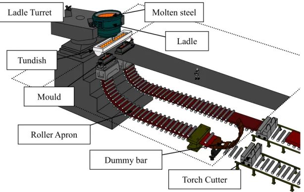
In general, the continuous casting (CC) process is widely used in steel industries for solidifying molten steel (95.6 % of world production in 2015 [World Steel Association]). The schematic of the CC machine is shown in Figure 1. The molten steel is charged in the ladle and it is poured into the mould through the tundish. It is first cooled in the mould (primary cooling). Spray cooling is then applied in the roller aprons; in other words, segments. This is called secondary cooling. Thanks to cooling, molten steel is solidified at the exit of the machine. The solidified steel is cut by the torch cutter at required length for later processing. The typical slab size is 0.25 m thick, 2 m width and 10 m long typically for automotive industry. For machine length and machine height around 40 m and 10 m, respectively, this figure corresponding to the radius of bending zone. Looking at the shape of slab in the CC, the bending shape is found first from the mould and the straight shape is seen close to the exit of the CC. It indicates that the bending slab is straightened at the bottom of the bending zone, called unbending.
Figure 1 Schematic of CC process
An example of recent standards regarding machine specification can be found in the literature [Yamaguchi 2012]. The advantages of the CC process are productivity, yield, energy, labor efficiency and quality assurance [Okumura 1994].
Ladle Turret Ladle Molten steel Tundish Mould Roller Apron Torch Cutter Dummy bar
3
2. Typical defects in CC
In the CC process, two types of defects appear: surface defects and internal defects. < Surface defects >
- Surface cracks due to the deformation of solidified skin in the mould or the deformation of solidified shell in the bending and unbending zone. These could be removed after the CC process by means of scarfing process up to a certain extent and although this affects the yield and cost.
- Inclusion problems due to slag or mould powder which are entrapped in the solidified skin in the mould. These defects are reduced thanks to optimization of liquid melt flow in the mould with electromagnetic tools. They could be removed as well as surface cracks.
< Internal defects >
- Hot tearing due to the deformation of solidified skin in the mould or the deformation of the solidified shell in the bending and unbending zone. Such cracks cannot be removed since they are located inside the slab.
- Macrosegregation due to the deformation of solidified shell in the segments close to the end of solidification. These heterogeneities in the chemical concentrations of alloy elements cannot be removed as well.
Two critical internal defects are hot tearing (in other words, internal crack) and macro segregation or axial segregation taking place during the secondary cooling process. Hot tearing leads to defect on a steel coil for automotive industry or makes crucial trouble during hot rolling before the coil is obtained due to fissure of the steel sheet. Macrosegregation leads to non uniform mechanical properties of the product and so-called high quality products for line pipe or special tanker components require constant properties, which requires minimum macro segregation.
4
3. Presentation of hot tearing and macrosegregation defects 3.1 Short presentation of defects in the CC process
The phenomena are understood as follows: during secondary cooling process, molten steel heat is removed from the surface of the solidified shell. Regarding microstructure, dendritic crystals grow toward liquid core from the solidified shell along the temperature gradient. It means the dendritic grains are constrained to the direction perpendicular to the slab surface. Tensile deformation along the casting direction perpendicular to which the dendrites are aligned generates due to bulging, bending, unbending and misalignment between rollers (see Figure 2 and Figure 3). The tensile deformation makes hot tearing [Lankford 1972, Brimacombe 1977] in between dendrites deep in the mushy zone; typically over 0.9 fraction of solid phase. Since hot tearing takes place in the mushy zone, it is easily imagined that the solidification path based on microsegregation phenomena has an important role.
Figure 2 Schematic of bulging and misalignment [Lankford 1972] and consequences in terms of tensile
or compressive stresses.
5
Figure 3 Schematic of bending process and simple estimation of strain and strain rate [Lankford 1972].
Close to the solidification end, macrosegregation generates due to enriched melt flow because of the complex combination among solidified shell deformation, shrinkage, induced fluid flow and solute transport [Miyazawa 1981], [Kajitani 2001], [Fachinotti 2006] and [Mayer 2010]. This defect is also connected with solidification path because it occurs in mushy zone, but in the specific context of CC process, solidified shell deformation and shrinkage could have an important role for the formation of macrosegregation. Concerning solidified shell deformation, it could be sure that bulging takes place in between rolls close to the end of solidification because of ferrostatic pressure depending on machine height. It then makes deformation of mushy zone in which the solid phase is deformed and the liquid phase is circulated due to solid phase movement. Because of the flow of the liquid with enriched solutes, composition field becomes varied, leading to macrosegregation. Second, shrinkage makes also liquid flow in mushy zone, resulting in variation of composition, that is to say, macrosegregation. In the CC process, it is quite popular that soft reduction is applied to solidifying slab close to the end of the melting pool. It means that slab thickness is gradually reduced due to decreasing roll gaps on a certain distance. The mechanical thickness reduction of the slab can compensate solidification shrinkage, leading to less liquid circulation close to the end of solidification, and, as a consequence, less marked segregation.
6
3.2 Hot tearing phenomena 3.2.1 Solidification stages
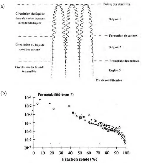
Solidification is the transformation from liquid phase to solid phase. This transformation occurs continuously and a mixture of solid and liquid phases coexist in what is called the mushy zone. The range between the solidus and the liquidus temperatures is called solidification interval. For a columnar structure, this solidification interval is generally divided into three regions, schematized in Figure 4. In regions 1 and 2, the mushy zone can absorb external tensile stress because of the capacity of the solid and the liquid phases to move. Thus, the sensitivity to cracking is relatively low. In contrast, when the solidification reaches region 3, the sensitivity becomes higher. Indeed, in this region, liquid films are isolated and the permeability in the mush falls dramatically up to the completion of solidification. Cracks that form in these conditions are known as hot tears, they are generally intergranular.
3.2.2 Different modes of hot tearing
Uniaxial tensile tests results, using aluminum alloys in mushy zone carried out by Braccini [Braccini 2000] and Ludwig et al. [Ludwig 2004], show that solid fraction has an important role for the material behavior. The solidification interval is divided into three stages.
cohe
s g
g : There is no mechanical resistance because of no solid bridges (region 1 in
Figure 4(a)). coal s s cohe s g g
g : The mechanical resistance appears and it results in the loss of ductility (region 2 in Figure 4(a)).
coal s
s g
g : Both the ductility and the mechanical resistance rapidly increase (region 3 in Figure 4(a)).
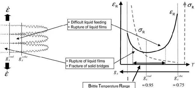
Figure 5 illustrates schematics of the main phenomena occurring in the mushy zone at characteristic solid fractions, above mentioned, explaining the loss of ductility in a given Brittle Temperature Range of the solidification.
7
Figure 4 On the top, schematic of the solidification interval of a columnar structure, on the bottom,
relation between the permeability and the solid fraction [Wintz 1994].
Braccini [Braccini 2000] have brought experimental evidences, in the case of aluminum alloys, of some specific cracking modes, depending on the solid fraction.
In the case of low solid fraction: coal s
s g
g , hot tearing is due to propagation of
rupture in the liquid films at the interface of the grains (Figure 6(a)). Then the surface tension of the liquid resists the propagation of the rupture. When this region is
subject to excess stress, liquid films finally tear and peaks of liquid remain, as shown in Figure 6(c).
In the case of the high solid fraction: coal s
s g
g , plastic deformation occurs in between solid bridges and leads to ductility (Figure 6(b)). The plastic deformation coexists with the previous rupture mechanism. However, these two types of rupture in this region can be distinguished (appearance between the dendrites of same grain or grains).
(b) (a)
8
Figure 5 Schematics of the main phenomena occurring in the mushy zone at characteristic solid
fractions, explaining the loss of ductility in a given Brittle Temperature Range [Bellet 2009].
Figure 6 Illustration of faces of fracture surface [Braccini 2000]: (a) brittle failure in interdendritic
region, (b) ductile rupture of solid bridges, (c) observation of a peak of stretched liquid.
3.2.3 Various parameters effect on hot tearing (1) Influence of solidification interval
Chemical composition determines solidification interval. The larger the solidification interval is, the higher the hot tearing sensitivity becomes. The fragility strongly depends on the solidification path through the kinetic of liquid disappearance near the end of solidification. Consequently, hot tearing depends on the chemical composition, particularly for elements such as sulfur, phosphorus and boron: these elements make solidus temperature lower and hot tearing sensitivity increases [Wintz 1994]. The effect of sulfur can be prevented by adding manganese. Indeed, manganese favors
9
precipitation of (Fe,Mn)S intermetallic, with higher solidus temperature. The effect of carbon content is not as clear. While it is believed that carbon makes the solidification interval widen, it was observed that, over 0.3wt% carbon content in Fe-C alloy, the higher the carbon content is, the smaller the hot tearing risk becomes [Pierer 2007].
(2) Influence of microstructure
The microstructure is linked to the solidification path. A fine microstructure decreases the sensitivity for the appearance of the rupture by the adaptation of the deformation: gliding at grain boundary can absorb deformation [Pierer 2007]. Ductility of the equiaxed structure is better than with columnar structure [Eskin 2004]. The microstructure also influences the mechanical behavior in the mushy zone and the permeability.
The metallurgical phases in presence also influence the occurrence of hot tearing during solidification. Several studies illustrate this influence in the case of stainless steels [Katayama 1985] and [Kotecki 1993]. It is explained that it is more difficult to propagate the rupture in a mixed structure. This influence is verified using two elements, that is, sulfur and phosphorus. The result is that these two elements are easily soluble in ferrite but not in austenite; this means that the kinetic of the disappearance of the liquid near the end of solidification depends on the quantity of the austenite phase. In addition, shrinkage corresponding to the transformation from ferrite to austenite generates the deformation in the mush and modifies the hot tearing sensitivity.
Grain boundary misorientation angle has also an effect on the occurrence of hot tearing during solidification [Wang 2004]. Over a certain critical angle between two metallurgical grains, the undercooling required to overcome the repulsive forces before the grains bridge is large. As a consequence, and as illustrated in Figure 7, there is an extended region where interdendritic liquid films remain, creating a low strength zone along the future grain boundary. When a tensile strain is applied perpendicular to the average dendrite growth direction, hot tearing takes place preferably in this brittle region along the grain boundary.
10
Figure 7 Schematic illustration from [Wang 2004] showing the effect of delayed coalescence in case of
significant misorientation between grains. This leads to the persistence of liquid pockets along such grain boundaries below the nominal coalescence temperature of the single crystal.
(3) Influence of solid/liquid wetting angle
The wetting angle at the interface of the solid also influences the sensitivity to hot tearing [Braccini 2000]. The wetting angle results in the capacity of the liquid to spread on the surface of the solid as a function of temperature and the liquid composition. This determines the distribution of the liquid film at the interface of the grains, that is, films are continued, discontinued or become pockets, shown as Figure 8. The angle is defined by GB2SLcos, where GB and SL are respectively the surface energy of the grain boundary and the surface energy of the liquid-solid interface. Figure 8 shows typical distribution of liquid as a function as the angle . Some tensile tests in a SEM to investigate the relation between the wetting angle and the rupture were carried out by Fredriksson and Lehtinen [Fredriksson 1979]. The authors show that the angle is null for Al-Sn alloys and hot tearing appears in the wetting grains. In the case of Al-Cd alloys, the angle is high and the wetted pockets do not influence the rupture. Finally the authors pointed out the role of the grain boundaries wetted by the liquid and oriented in a direction perpendicular to the traction rupture.
Thickness of the liquid film also influences the sensitivity to hot tearing. The larger the thickness is, the higher the appearance of the hot tearing becomes. However, it is necessary to investigate the characteristics of the liquid film at high temperature [Gerds 1976].
11
Figure 8 Distributions of liquid film in a surface of a grain [Braccini 2000].
(4) Influence of thermomechanics
Thermomechanics has an important role for the occurrence of hot tearing. Physical property of alloy is strongly associated with temperature. Thus, thermal evolution determines the mechanical effect, such as deformation and shrinkage. It results in a driving force for the occurrence of the hot tearing. Geometric effects (for instance, bending and unbending materials during solidification in continuous casting process) also lead to the appearance of hot tear.
3.3 Deformation induced segregation
As explained in the previous sections, macrosegregation results from deformation of the solidified shell in the CC process. In fact, deformation of the mush is the origin of macrosegregation. The mush is composed of solid and liquid phase. The mushy solid is considered as sponge like material which contains enriched liquid. When the sponge is in compression, the enriched liquid is expelled outside, leading to negative macrosegregation in the deformation area. When the sponge is in traction, the enriched liquid is sucked inside of the sponge, leading to positive macrosegregation. This is called deformation induced segregation and the liquid phase is transported with enriched solutes according to the mushy solid deformation. Concerning the intensity of the macrosegregation with respect to solute elements, solute for instance like P and S which have low partition coefficient makes strong segregation.
12
4. Prediction of hot tearing through numerical modelling
Regarding with modeling of hot tearing, there are several recent studies in this field. They can be divided into two groups; micro and macroscopic scale studies. The last decade has seen a significant development of numerical simulations directly operated at the scale of a Representative Elementary Volume (REV) of the mushy material, in view of encompassing most of the small-scale physical phenomena mentioned above. Phillion et al. [Phillion 2008] showed the influence of microstructual features on tensile deformation of a REV of semi-solid aluminum alloy. Sistaninia et al. [Sistaninia 2011] have developed a numerical simulation using a discrete element method in order to account for the strain inhomogeneity in the mushy zone due to crack initiation and propagation, in other words, direct simulation of hot tearing. Zaragoci et al. [Zaragoci 2012] considered a domain of few cubic millimeters deduced from in-situ X-ray tomography of a tensile test in an Al-Cu sample maintained in the mushy state. A finite element discretization of the 3D domain using the level set method and adaptive mesh refinement was conducted to accurately separate liquid films and grains. The liquid flow and grain deformation were calculated, intrinsic properties of the phases obeying a viscoplastic constitutive equation. However, in those recent works [Phillion 2008], [Sistaninia 2011] and [Zaragoci 2012], only fragments of the different physical phenomena taking part in hot tearing were accounted for. It can be thought that such small-scale models will develop in the future, integrating more and more relevant physical features, and thus will become useful tools for a better fundamental understanding of hot tearing. But upscaling of such models to deduce rules that can be applied at the processing scale, such as in continuous casting, will require time due to their computational cost and actual approximations of the physical phenomena. Therefore, it is necessary to focus on more macroscopic analysis methods to study hot tearing. Those constitute the second group of researches mentioned previously, if one is targeting process scale applications. In the literature, lots of studies have proposed hot tearing criteria based on thermal considerations [Clyne 1977], solid mechanics [Prokhorov 1962], [Rogberg 1987], [Nagata 1990], [Yamanaka 1991], [Won 2000], [Cerri 2007] and [Bellet 2009] or solid and fluid mechanics [Rappaz 1999]. Cerri et al. [Cerri 2007], [Bellet 2009] have evaluated four of those hot tearing criteria for steels [Clyne 1977], [Prokhorov 1962], [Won 2000] and [Rappaz 1999] by means of constrained shrinkage tests and ingot bending tests. Systematic numerical simulation of the tests was conducted with the finite element package THERCAST® equipped with the different macroscopic criteria. The authors concluded that the only criterion able to
13
show a qualitative agreement with the experimental tests was the strain-based criterion proposed by Won et al. [Won 2000]. They proposed an enriched expression to reach quantitative agreement [Cerri 2007], [Bellet 2009]. In addition, Pierer et al. [Pierer 2007] evaluated, by use of submerged split chill tensile tests, a stress-based criterion [Rogberg 1987], a strain-based criterion [Won 2000], a criterion based on strain rate and including liquid feeding consideration [Rappaz 1999] and a criterion based on the sole BTR value [Clyne 1977]. The authors found that only the stress-based criterion and the strain-based criterion had good capability for predicting hot tearing. As a consequence, in the framework of the present study, we will essentially focus on hot tearing criteria based on critical strain.
14
5. Prediction of macrosegregation by numerical modeling
Several researchers studied these phenomena in the context of CC process with numerical modeling. Miyazawa and Schwerdtfeger [Miyazawa 1981] modelled solidification and macrosegregation, considering bulging between support rolls and the associated mushy zone deformation. In their model, mass, liquid phase momentum, solute and energy conservation equations are described in a fully Eulerian approach. The solid phase momentum equation is not solved so the velocity fields of the solid shell and of the solid phase in the central mushy region are arbitrarily given. The numerical simulation shows the formation of a center line with positive macrosegregation due to bulging. Kajitani et al. [Kajitani 2001] and Mayer et al. [Mayer 2010] studied the so-called soft reduction process using the same approach and discussed the quantitative impact of the soft reduction technique to reduce the intensity of the central macrosegregation. Fachinotti et al. [Fachinotti 2006] developed a different approach to model the mushy zone in the context of CC, using an arbitrary Lagrangian-Eulerian approach in which solid and liquid velocity fields are concurrently solved for, avoiding then the strong hypothesis over the solid velocity field which was present in previous works. With this model, the authors simulated continuous casting and similarly retrieved the effect of bulging on the formation of central macrosegregation [Bellet 2007]. More recently, Rivaux [Rivaux 2011] developed an alternative approach to model the deformation of the solid phase and its Darcy-type interaction with the liquid phase in the mushy state, through a staggered scheme in which the two fields are separately and successively solved for at each time increment. However, in the end, it should be said that despite lot of efforts in developing those numerical models, none of them has been successfully applied up to the scale of a 3D simulation representative of the complexity of the industrial process. This is certainly due to the considerable amount of computational power required to run the models encompassing a significant part of the secondary cooling section of an industrial caster.
15
6. Microsegregation modeling for multicomponent steels
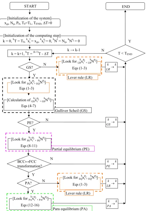
Average alloy properties in multiphase temperature intervals are important for thermomechanical process simulations. Numerical tools have been developed to follow the transformation paths based on thermodynamic considerations. Two classical limits are routinely computed: the lever rule (LR) approximation and the Gulliver Scheil (GS) approximation [Gulliver 1913] and [Scheil 1943]. For LR, full equilibrium is assumed, meaning that all chemical elements can diffuse rapidly. In contrast, the GS approximation neglects diffusion in solid phases where elements are completely frozen. In practice, most industrial steels include interstitial and substitutional elements. Interstitial elements, such as carbon, have high diffusivity in the solid phase while substitutional elements have low diffusivity. Thus, the above LR and GS approximations do not fully apply. To overcome this problem, the partial equilibrium (PE) approximation [Chen 2002] and [Zhang 2013] has been developed. PE is intended to take into account perfect diffusion of interstitial elements but no diffusion of substitutional elements. However, the peritectic transformation often encountered in commercial alloys cannot take place if only PE is considered. This limitation could be circumvented by a LR treatment of the -BCC (or -ferrite)/-FCC (or -austenite) mixture during the peritectic transformation [Chen 2006], thus permitting the activation of the -BCC to -FCC phase transformation. This will be later refereed as PE+LR solidification path. It is to be mentioned that, while in agreement with observations, no experimental quantitative data is yet available that could be directly compared with predicted kinetics of the peritectic phase transformation. The LR treatment of the peritectic transformation is also a very crude approximation that does not fix the problem in coherent manner with respect to the PE approximation.
In the present study, a new numerical scheme is presented for the computation of phase transformations in steels. It is coupled with thermodynamic equilibrium calculations based on call to the software Thermo-Calc [Thermo-Calc 2013] through the TQ-interface using the TCFE6 database [Shi 2008]. The so-called para-equilibrium (PA) approximation presented by Hillert [Hillert 1998] has been introduced to deal with the peritectic reaction during a PE solidification path, later refereed as PE+PA approximation. This is implemented in previous developments presented by Zhang et al. [Chen 2002] for the computation of LR, GS and PE+LR solidification paths. Because PA was initially developed for solid state transformations, it is also used to simulate phase transformations during cooling experienced during steel processing after solidification. The PA treatment allows the activation of the -BCC to -FCC phase
16
transformation during solidification with the consideration of perfect diffusion of interstitial elements but no diffusion of substitutional elements which is consistent with PE. The numerical scheme is applied to steel alloys experiments also presented in this contribution.
Concerning coupling between microsegregation modeling and macrosegregation modeling for steels, some researchers employed the simplest system; Fe-C binary system [Miyazawa 1981], [Kajitani 2001], [Fachinotti 2006] and [Mayer 2010]. The advantage of this case is to simplify the implementation into the code. In case of binary system, constant liquidus slope and partition coefficient are assumed and LR or GS could be applied. However, commercial steels are generally multicomponent system so that microsegregation modeling for multicomponent steels is required for application to the CC simulation or an experiment for steel. Recently, some researchers [Carozzani 2012, Saad 2016] have developed a model for multicomponent where enthalpy and solute concentration are tabulated a priori. According to the result of global resolution such as enthalpy, momentum and solute conservation equations, the code refers the table and chooses suitable values. With this model, peritectic transformation can be taken into account for and more realistic simulation could be performed.
In this present study, simple binary model is extended to multicomponent system with some assumptions for coupling the macrosegregation and microsegregation although peritectic transformation cannot be considered. This model gives access to analyze the effect of each solute elements and the consequent macrosegregation compared to the experiment with steels. The detail of the model is explained in the following chapter.
17
7. Numerical modeling
To understand and analyze the above two defects, numerical modeling is one of the powerful tools. Potentially, the advantage of the numerical model is to predict the defects. It is also possible to optimize casting conditions according to numerical simulation results. Therefore, one objective in this thesis is to develop a numerical model which would be able to give a reliable and detailed description of the main phenomena leading to the defects mentioned above. In terms of modeling of CC process, ANSYS-FLUENT [FLUENT] is quite well known to be applied to melt flow modeling in tundish and mould. Regarding with modeling of slab deformation in secondary cooling process, THERCAST [Bellet 2004] and [Bellet 2005] developed by Transvalor strongly supported by CEMEF, MINES Paristech, is one of the solution because it is dedicated to the CC process modeling, especially secondary cooling process with deformation. It can be performed in three dimensional modeling with finite element approach. Regarding macrosegregation modeling in the CC, R2SOL [Fachinotti 2006] already developed at CEMEF is also dedicated to secondary cooling process especially with mushy zone deformation and solute transport modeling with finite element approach. Although the modeling is limited to two dimensions, solving deformation of the mush together with solute transport phenomena is quite interesting to understand what happens in the slab. As mentioned above, microsegregation is key role to hot tearing and macrosegregation phenomena. In addition, average alloy properties in multiphase temperature intervals are important for thermomechanical process simulations. Therefore, microsegregation modeling is interesting. In this study, Thermocalc [Thermo-Calc 2013] with thermodynamic consideration is used. Although boundary condition is limited, like full solute diffusion or not, realistic solidification path and thermo physical properties with multicomponent alloy would be obtained.
7.1 Presentation of THERCAST®
The numerical simulation of the experiments consists of a thermomechanical stress/strain analysis. It is conducted using the 3D finite element code THERCAST®. The essential characteristics of the code can be found in References [Bellet 2004] and [Bellet 2005]. Non-linear average conservation equations for the total mass, momentum and energy are solved at each time increment on all interacting domains. The solution covers the whole domain occupied by the metal, whatever its state: liquid, solid, or mushy and the components of the modeling system. The semi-solid steel (composed of
18
liquid and solid phases) is simply considered as a homogenized continuum with averaged properties and a unique average velocity field v. The thermal problem and the mechanical problem are solved sequentially at each time increment. First, the average energy conservation is solved in all domains taking into account heat exchange between them. This equation can be expressed by:
T
dt
dh
(1)
where is the average density, h is the average specific enthalpy per unit mass, is the average thermal conductivity and T is the temperature. Second, the mechanical problem is considered. The following average momentum and mass conservation equations are solved concurrently in the framework of a velocity-pressure formulation.
0 tr 0 vp ε γ g s p (2) where s is the deviatoric stress tensor, p is the pressure, g is the gravity vector, γ is the acceleration vector and ε is the viscoplastic part of the strain rate tensor:vp
2 / ) ( v Tv
ε (3)
The strain rate tensor is expressed as the sum of three different contributions: th
vp
el ε ε
ε
ε (4)
where ε is the thermal strain rate tensor. The alloy is modeled with a hybrid th
constitutive equation. Details can be found elsewhere [Thomas 2008], only main lines being recalled here. Over the solidus temperature, the alloy is considered as a non-Newtonian fluid obeying a temperature-dependent viscoplastic multiplicative law, as follows:
m mK
3 1 (5)
where is the equivalent von Mises stress, K is the viscoplastic consistency, is the generalized strain rate and m is the strain rate sensitivity. The value of m over the liquidus temperature is equal to 1 (Newtonian fluid). In the frame of the present study, liquid flow in liquid regions is ignored and the liquid viscosity is defined as 10 Pa s for
19
numerical stability reasons. Below the solidus temperature, the alloy obeys an elastic-viscoplastic constitutive equation, expressed by:
m m H nK
3 1 (6)
in which is the cumulated plastic strain, H is the strain hardening coefficient and n is the strain sensitivity. Physical properties and constitutive parameters are temperature dependent.
7.2 Presentation of R2SOL
The macrosegregation forms due to concurrent deformation of the solid phase in the mushy zone, and from the liquid flow induced by this deformation. In order to consider separately - but solve concurrently - for the liquid and solid velocity fields in the mushy zone, we apply the so-called "two-phase" model initially developed by Bellet et al. [Fachinotti 2006] and [Bellet 2007] to address macrosegregation in continuous casting. This model allows simulating solute transport phenomena leading to macrosegregation induced by deformation, shrinkage and advection. It is performed with the 2D finite element code R2SOL. The main assumptions and features of the model are reminded hereafter.
The conservation equations for the solid-liquid mixture are expressed on a representative elementary volume (REV) and are obtained using the spatial averaging method [Ni 1991].
The mushy material is considered as a saturated two-phase medium only made of solid, s, and liquid, l (i.e. no porosity and gsgl 1 where gk denotes the volume fraction of phase k).
At the so-called microscopic scale, within the REV, the liquid phase is considered as an incompressible Newtonian fluid. After spatial averaging, the macroscopic behavior of the liquid phase is Newtonian compressible.
In the same way, the solid phase is considered intrinsically as an incompressible non-Newtonian fluid, and its macroscopic averaged behavior is the one of a compressible non-Newtonian fluid for which inertia effects are neglected.
The momentum interaction between solid and liquid phases is formulated with an isotropic Darcy law.
20
Solidification shrinkage is taken into account by considering different densities for the solid and liquid phases, respectively ρS and ρL. Those values are assumed constant within the solidification interval.
A multi component system under lever rule approximation is assumed, meaning that the partition coefficient ki and the liquidus slope mi are constant for each solute element i.
Local thermal equilibrium holds within the REV, ensuring the uniformity of temperature within the different phases.
The previous assumptions lead to the following set of averaged conservation equations:
0 ) ( 1 2 Σs gs pl gl l vl vs gsSg (7) ) ( ) ( ) ( 1 2 l l l L l l L L l s l l l l l l g t g g g p g v v g v v v s (8) t g g g s L S L s s L S l l ) ( ) ( v v (9) 0 ) ( )) ( ( T g g L h t h s l s l v v v (10) 0 ) ( )) ( ( ) ( , , , i l i l l s l i l l s i i w gw g D w t w v v v (11)
in which vs and vl are the solid and liquid velocity vectors (intrinsic average phase velocities: v l vl l; v s vs s), pl is the liquid phase pressure (
l l
l p
p ), μl is the dynamic viscosity of the liquid phase,
and
are the average density and the average heat conductivity of the solid-liquid mixture, h is the average enthalpy of the mixture. wi and wl,i are respectively the average solute mass concentrationand the intrinsic average concentration in the liquid phase for each solute i. In the momentum equations, the Darcy term introduces the permeability κ of the porous medium constituted by the solid phase. It is derived from the liquid volume fraction and the secondary dendrite arm spacing 2, through the Carman-Kozeny model.
21 2 3 2 2 ) 1 ( 180 l l g g (12)
Constitutive models for the liquid and the solid phases in the mushy zone are presented in detail in references [Fachinotti 2006] and [Bellet 2007]. In summary, the average deviatoric stress tensor in the liquid phase is expressed by:
tr( ( )) 3 1 ) ( 2 ) ( dev 2 l l l l l l l l g ε v g ε v ε v s (13)where ε(vl) is the symmetric part of the liquid velocity gradient vl. For solid, it is assumed that the behavior of the fully solid material is viscoplastic, of power law type, as will be introduced later. The strain-rate sensitivity coefficient of the fully solid material being denoted m, it can be shown that the effective macroscopic stress tensor for the solid phase in the mushy state, Σ σ lI
s
p
, is a degree m homogeneous
function with respect to the strain rate tensor ε s ε(vs). Adopting a compressible viscoplastic potential, its expression writes:
I ε ε I ε ε Σ s s m s s s m s s B A K A B A K tr 9 1 ) dev( 1 ) 3 ( 3 tr 3 1 9 1 1 ) 3 ( 3 1 1 (14)
in which K is the viscoplastic consistency of the solid material and m its strain rate sensitivity, both taken at the solidus temperature. The equivalent strain rate s is expressed by
22 2 1 2 2 1 2 ) (tr 9 1 ) dev( : ) dev( 1 ) (tr 3 1 9 1 : 1 s s s s s s s B A A B A ε ε ε ε ε ε (15)
In the flow rule (Eq. (14)), A and B are two rheological coefficients depending on the solid volume fraction. In the present study, the expressions introduced in reference [Fachinotti 2006] are used:
crit s s s B g g g k B 1 (1 ) 2 3 B k A A (16)
The values of the parameters are taken from the same reference. Taking the trace of Eq. (14), it can be seen that the compressibility of the solid phase is essentially controlled by the value of coefficient B:
s m s s B K ε Σ ( 3 ) 1tr tr 1 (17)
As expressed by Eq. (16a), gcrits can be seen as the coherency solid volume fraction at which the compressibility of the solid phase is extremely high (B). Conversely, when the solid fraction tends to one (fully solid material), A and B tend toward 3/2 and 0, respectively: the usual power law relating stress and strain rate for a dense metal at high temperature is retrieved.
In the finite element code, the weak (integral) form of Eqs. (7) to (11) is implemented in 2D triangular finite elements. At each time increment, the sequence of numerical resolutions is as follows:
- The thermal resolution is operated on the set of the different domains involved: in the present context, the solidifying ingot, the different components of the mold, and the pressing punch. The (non-linear) heat transfer resolution is carried out on each domain, successively, up to convergence (i.e. stabilization of the temperature field). In the ingot, a finite element (FE) resolution of Eq. (10) is done, while in the other domains a more classical single phase form of heat diffusion is solved. Heat
23
exchanges at interfaces between domains are expressed by the Fourier law, using heat transfer coefficients.
- The macrosegregation resolution is performed in the ingot, through a FE resolution of Eq. (11) for each considered solute i. In these resolutions, like in the thermal one, the microsegregation model (here the lever rule) is considered as it links the average concentrations in the liquid phase wl,i with the average mixture concentrations
i
w , and the averaged enthalpy h with the temperature T.
- The mechanical resolution is performed in the ingot, the other domains being assumed perfectly rigid and fixed. A non-linear Newton-Raphson algorithm is used, providing the nodal values of vs, vl and pl through a single FE resolution of Eqs. (7) to (9). As the mechanical formulation presented above encompasses the central mushy zone and the fully solidified regions, a specific treatment applies. In the finite element assembly procedure, elements are considered either mushy or fully solid, according to the temperature at their center. In mushy elements, the contribution to the residue directly results from the weak form of Eqs. (7) to (9). In fully solid elements, it can be noted that, by applying these equations, the liquid velocity is still present but has no real physical meaning: it is then kept close to the solid velocity field by means of the sole Darcy term in the liquid momentum equation, acting as a penalty term. The deviatoric stress tensor s is expressed as a function of the velocity field by the viscoplastic Norton-Hoff power law including strain hardening:
) ( dev ) 3 ( 2 1 ε s K
n
m (18)where dev ε( ) denotes the deviatoric part of the strain rate tensor, K the viscoplastic consistency, m the strain rate sensitivity coefficient, the generalized strain rate and the generalized strain. Strain-hardening is assumed null at solidus temperature and over. This is why only K (and not K ) appears in Eq.(14) to n
express the behavior model of the solid phase in the mush. The tensor equation (18) yields the one dimensional relation between the von Mises stress and the generalized strain-rate : m n m K
( 3) 1 (19)24
The fully solid metal is then plastically incompressible and this is why Eq. (9) is replaced in the finite elements which are found fully solid (temperature at center lower than the solidus temperature) by the following equation which simply accounts for thermal dilatation terms:
0 d ) ( d ) ( 1 t T T s s s v (20)
25
8. Large scale experiment
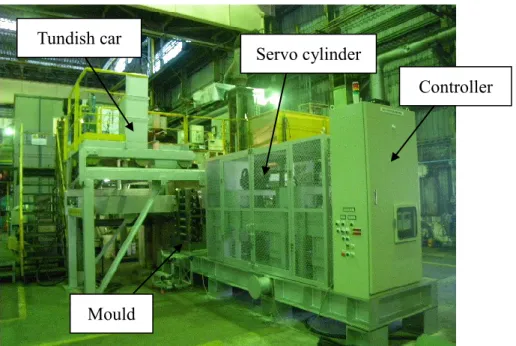
In order to understand solidification defects; hot tearing and macrosegregation, a large scale experiment developed at Nippon Steel & Sumitomo Metal is employed. Its view is shown in Figure 9. In the late 1970s, such a large scale ingot punching test has been developed by steel industries in Japan [Sato 1975], [Miyamura 1976], [Marukawa 1978], [Narita 1978] and [Sugitani 1980] to estimate the CC-process viability. Such test has been also developed in Europe [Wintz 1994] in 1990s. They consist in bending, punching, or pressing the solidifying shell of an ingot during its solidification by means of a punch moved perpendicularly to the shell plane (or surface of the ingot), i.e. along the dendritic growth direction when solidification proceeds directionally away from the mold walls. The size of the ingot and the control of the bending/punching conditions have to represent the solicitations undergone by the solid shell during CC when it passes by the support rolls. Note that in CC, the alloy also endures the metallostatic pressure which induces bulging between each roll stand. The concept of the apparatus is similar to the above references, the deformation being applied on an ingot which is not fully solidified. The steel ingot thickness is 0.16 m so that solidification time is close to real process, around 15 min. It gives similar solidification microstructure and defects. What is nice in this named ingot punch pressing test is to control deformation using a servo hydraulic cylinder, saying that displacement and velocity of the punch are easily controlled. In addition to the control of deformation, solidification progress is monitored using thermocouple in the ingot. Using this monitoring together with numerical modeling, it is then possible to predict the ingot core solidification. At last, the defects like hot tearing and macrosegregation are successfully created. The detail of the experiment is presented in following chapter.
26
Figure 9 Entire view of ingot pressing test developed at Nippon Steel & Sumitomo Metal Corporation.
Steel mould is located at the centre of the photo and 450 kg molten metal is prepared in a ladle over the mould and it is introduced into the mould through a tundish. In fact, the servo cylinder which is in change to the punch movement and so the deformation on an ingot.
This thesis consists of 3 articles; Chapter II explains microsegregation modeling for multicomponent steels based on thermodynamical point of view. A new numerical scheme is developed and the simulation results are discussed with experimental results. Chapter III presents prediction of hot tearing through 3D thermomechanical modeling with ingot punch pressing test. An excellent correlation in between the numerical results and observed cracks are seen and solidification path effect is then discussed. Chapter IV is linked to prediction of macrosegregation by 2D numerical modeling with ingot punch pressing test. The numerical simulation results show the essential of the driving force of the generation of macrosegregation. Chapter V and VI are then summary and perspective.
Servo cylinder
Controller
Mould Tundish car
29
Chapter II
Computation of Phase Transformation Paths
in Steels by a Combination of the Partial-
and
Para-equilibrium
Thermodynamic
Approximations
Takao KOSHIKAWA, Charles-André GANDIN, Michel BELLET, Hideaki YAMAMURA and Manuel BOBADILLA
DOI: http://dx.doi.org/10.2355/isijinternational.54.1274
© 2014 ISIJ 1274
ISIJ International, Vol. 54 (2014), No. 6, pp. 1274–1282
Computation of Phase Transformation Paths in Steels by a
Combination of the Partial- and Para-equilibrium Thermodynamic
Approximations
Takao KOSHIKAWA,1,2)* Charles-André GANDIN,1) Michel BELLET,1) Hideaki YAMAMURA3) and
Manuel BOBADILLA4)
1) MINES ParisTech & CNRS, CEMEF UMR 7635, 06904 Sophia Antipolis, France.
2) Nippon Steel & Sumitomo Metal Corporation, Oita Works Equipment Division, 1 Oaza-Nishinosu, Oita City, Oita Prefecture, 870-0992 Japan. 3) Nippon Steel & Sumitomo Metal Corporation, Steelmaking R&D Division, 20-1 Shintomi, Futtsu City, Chiba Prefecture, 293-8511 Japan.
4) ArcelorMittal Maizières, Research and Development, BP 30320, 57283 Maizières-lès-Metz Cedex, France. (Received on August 29, 2013; accepted on February 13, 2014)
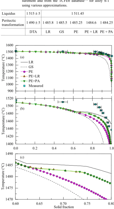
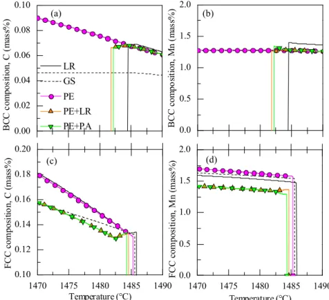
A model combining the partial-equilibrium and para-equilibrium thermodynamic approximations is pre-sented. It accounts for fast diffusion of interstitial elements, such as carbon, and low diffusion of substi-tutional elements in the solid phases, while complete mixing is assumed for all elements in the liquid phase. These considerations are turned into classical mathematical expressions for the chemical poten-tials and the u-fractions, to which mass conservation equations are added. The combination of the two models permits application to steels, dealing with partial-equilibrium for solidification and para-equilibrium for both the δ-BCC to γ-FCC peritectic transformation and the γ-FCC to α-BCC solid state transformation. The numerical scheme makes use of calls to Thermo-Calc and the TQ-interface for calculating thermody-namic equilibrium and accessing data from the TCFE6 database. Applications are given for a commercial steel. The results are discussed based on comparison with classical microsegregation models and exper-imental data.
KEY WORDS: solidification; microsegregation; partial-equilibrium; para-equilibrium; peritectic transformation.
1. Introduction
Average alloy properties in multiphase temperature inter-vals are important for thermomechanical process simula-tions. Numerical tools have been developed to follow the transformation paths based on thermodynamic consider-ations. Two classical limits are routinely computed: the lever rule (LR) approximation and the Gulliver-Scheil (GS) approximation.1,2) For LR, full equilibrium is assumed,
meaning that all chemical elements can diffuse rapidly. In contrast, the GS approximation neglects diffusion in solid phases where elements are completely frozen. In practice, most industrial steels include interstitial and substitutional elements. Interstitial elements, such as carbon, have high diffusivity in the solid phase while substitutional elements have low diffusivity. Thus, the above LR and GS approxi-mations do not fully apply. To overcome this problem, the partial-equilibrium (PE) approximation3,4) has been
devel-oped. PE is intended to take into account perfect diffusion of interstitial elements but no diffusion of substitutional ele-ments. However, the peritectic transformation often encoun-tered in commercial alloys cannot take place if only PE is
considered. This limitation could be circumvented by a LR treatment of the δ-BCC (or δ-ferrite)/γ-FCC (or γ-austenite) mixture during the peritectic transformation,5) thus
permit-ting the activation of the δ-BCC to γ-FCC phase transfor-mation. This will be later refereed as PE + LR solidification path. It is to be mentioned that, while in agreement with observations, no experimental quantitative data is yet avail-able that could be directly compared with predicted kinetics of the peritectic phase transformation. The LR treatment of the peritectic transformation is also a very crude approxima-tion that does not fix the problem in coherent manner with respect to the PE approximation.
In the present study, a new numerical scheme is presented for the computation of phase transformations in steels. It is coupled with thermodynamic equilibrium calculations based on call to the software Thermo-Calc6) through the
TQ-interface using the TCFE6 database.7) The so-called
para-equilibrium (PA) approximation presented by Hillert8)
has been introduced to deal with the peritectic reaction dur-ing a PE solidification path, later refereed as PE + PA approximation. This is implemented in previous develop-ments presented by Zhang et al.4) for the computation of LR,
GS and PE + LR solidification paths. Because PA was ini-tially developed for solid state transformations, it is also used to simulate phase transformations during cooling expe-* Corresponding author: E-mail: [email protected]
![Figure 2 Schematic of bulging and misalignment [Lankford 1972] and consequences in terms of tensile](https://thumb-eu.123doks.com/thumbv2/123doknet/2992970.83807/19.892.295.699.590.839/figure-schematic-bulging-misalignment-lankford-consequences-terms-tensile.webp)
![Figure 3 Schematic of bending process and simple estimation of strain and strain rate [Lankford 1972]](https://thumb-eu.123doks.com/thumbv2/123doknet/2992970.83807/20.892.237.657.150.386/figure-schematic-bending-process-simple-estimation-strain-lankford.webp)
![Figure 7 Schematic illustration from [Wang 2004] showing the effect of delayed coalescence in case of](https://thumb-eu.123doks.com/thumbv2/123doknet/2992970.83807/25.892.191.699.153.382/figure-schematic-illustration-wang-showing-effect-delayed-coalescence.webp)